
User Guide
Page 3
FILE LOCATION: C:\Users\gina\Desktop\Checkout_new\Maintenance Projects\Dell Contax\Dell_ContaxUG_PrintTOC.fm Table of Contents 1 Preface 13 2 Features 14 IP Version 6 (IPv6) Support 15 Stack Support 15 Power over Ethernet 15 Green Ethernet 16 Head of Line Blocking Prevention 16 Flow Control Support (IEEE 802.3X 16 Back Pressure Support 16 Virtual Cable Testing (VCT 17 Auto-Negotiation 17 MDI/MDIX Support 17 MAC Address Supported Features 17 Layer 2 Features 19 IGMP Snooping 19 Port Mirroring 19 Broadcast Storm Control 19 VLAN Supported Features 20 Contents 3
FILE LOCATION: C:\Users\gina\Desktop\Checkout_new\Maintenance Projects\Dell Contax\Dell_ContaxUG_PrintTOC.fm Table of Contents 1 Preface 13 2 Features 14 IP Version 6 (IPv6) Support 15 Stack Support 15 Power over Ethernet 15 Green Ethernet 16 Head of Line Blocking Prevention 16 Flow Control Support (IEEE 802.3X 16 Back Pressure Support 16 Virtual Cable Testing (VCT 17 Auto-Negotiation 17 MDI/MDIX Support 17 MAC Address Supported Features 17 Layer 2 Features 19 IGMP Snooping 19 Port Mirroring 19 Broadcast Storm Control 19 VLAN Supported Features 20 Contents 3
User Guide
Page 4
FILE LOCATION: C:\Users\gina\Desktop\Checkout_new\Maintenance Projects\Dell Contax\Dell_ContaxUG_PrintTOC.fm Spanning Tree Protocol Features 21 Link Aggregation 23 Quality of Service Features 23 Device Management Features 24 Security Features 28 Port Profile (CLI Macro 30 DHCP Server 31 Protected Ports 31 iSCSI Optimization 31 Proprietary Protocol Filtering 31 3 Hardware Description 33 Device Models 34 Device Structure 34 LED Definitions 38 Power Supplies 42 4 Stacking Overview 43 Stack Overview 44 Stack Members and Unit IDs 47 4 Contents
FILE LOCATION: C:\Users\gina\Desktop\Checkout_new\Maintenance Projects\Dell Contax\Dell_ContaxUG_PrintTOC.fm Spanning Tree Protocol Features 21 Link Aggregation 23 Quality of Service Features 23 Device Management Features 24 Security Features 28 Port Profile (CLI Macro 30 DHCP Server 31 Protected Ports 31 iSCSI Optimization 31 Proprietary Protocol Filtering 31 3 Hardware Description 33 Device Models 34 Device Structure 34 LED Definitions 38 Power Supplies 42 4 Stacking Overview 43 Stack Overview 44 Stack Members and Unit IDs 47 4 Contents
User Guide
Page 5
FILE LOCATION: C:\Users\gina\Desktop\Checkout_new\Maintenance Projects\Dell Contax\Dell_ContaxUG_PrintTOC.fm 5 Configuring the Switch 54 Configuration Work Flow 55 Connecting the Switch to the Terminal 56 Booting the Switch 57 Configuring the Stack 58 Configuration Using the Setup Wizard 58 6 Advanced Switch Configuration 63 Using the CLI 64 Accessing the Device Through...
FILE LOCATION: C:\Users\gina\Desktop\Checkout_new\Maintenance Projects\Dell Contax\Dell_ContaxUG_PrintTOC.fm 5 Configuring the Switch 54 Configuration Work Flow 55 Connecting the Switch to the Terminal 56 Booting the Switch 57 Configuring the Stack 58 Configuration Using the Setup Wizard 58 6 Advanced Switch Configuration 63 Using the CLI 64 Accessing the Device Through...
User Guide
Page 14
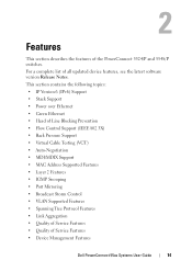
This section contains the following topics: • IP Version 6 (IPv6) Support • Stack Support • Power over Ethernet • Green Ethernet • Head of Line Blocking Prevention • Flow Control Support (IEEE 802.3X) • Back Pressure Support &#... Features • Quality of all updated device features, see the latest software version Release Notes. For a complete list of Service Features • Device Management Features Dell PowerConnect 55xx Systems User Guide 14 2 Features This section describes the features of the PowerConnect 5524/P and 5548/P switches.
This section contains the following topics: • IP Version 6 (IPv6) Support • Stack Support • Power over Ethernet • Green Ethernet • Head of Line Blocking Prevention • Flow Control Support (IEEE 802.3X) • Back Pressure Support &#... Features • Quality of all updated device features, see the latest software version Release Notes. For a complete list of Service Features • Device Management Features Dell PowerConnect 55xx Systems User Guide 14 2 Features This section describes the features of the PowerConnect 5524/P and 5548/P switches.
User Guide
Page 15
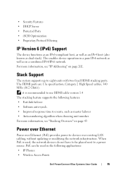
...network devices do not have to devices over Ethernet (PoE) provides power to be used in a pure IPv6 network as well as dual stack). The HDMI ports are 1.3a specification, Category 2 High Speed cables, 340 MHz (10.2 Gbit/s). This enables device operation in the ... • Software auto-synch. • Improved response time to use HDMI cable version 1.4 The stacking feature supports the following applications: • IP Phones • Wireless Access Points Dell PowerConnect 55xx Systems User Guide 15 For more information, see "IP Addressing" on page 43 Power over Ethernet...
...network devices do not have to devices over Ethernet (PoE) provides power to be used in a pure IPv6 network as well as dual stack). The HDMI ports are 1.3a specification, Category 2 High Speed cables, 340 MHz (10.2 Gbit/s). This enables device operation in the ... • Software auto-synch. • Improved response time to use HDMI cable version 1.4 The stacking feature supports the following applications: • IP Phones • Wireless Access Points Dell PowerConnect 55xx Systems User Guide 15 For more information, see "IP Addressing" on page 43 Power over Ethernet...
User Guide
Page 21
... enabled, the port receives limited network access through the Guest VLAN. Dell PowerConnect 55xx Systems User Guide 21 If a port is denied network access via port-based authorization, but the Guest VLAN is dropped from the Voice VLAN in the same stack). For more information, see "Private VLAN" on page 127. The subscribers...
... enabled, the port receives limited network access through the Guest VLAN. Dell PowerConnect 55xx Systems User Guide 21 If a port is denied network access via port-based authorization, but the Guest VLAN is dropped from the Voice VLAN in the same stack). For more information, see "Private VLAN" on page 127. The subscribers...

User Guide
Page 32
.... For more information, see Unit Identification (Location). 32 Dell PowerConnect 55xx Systems User Guide Identifying a Switch via LED The switch provides the ability to send additional client information, upon requesting an IP address. For more information, see "DHCP Relay" on all units in a stack for a specific length of time. Option 82 specifies the...
.... For more information, see Unit Identification (Location). 32 Dell PowerConnect 55xx Systems User Guide Identifying a Switch via LED The switch provides the ability to send additional client information, upon requesting an IP address. For more information, see "DHCP Relay" on all units in a stack for a specific length of time. Option 82 specifies the...
User Guide
Page 35
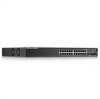
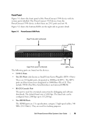
PowerConnect 5548 Ports Giga Ports (odd numbered) ConsoleUSB Port Port HDMI Ports Giga Ports (even numbered) SPF+ ... or LX. The baud rate can be configured from the PowerConnect 5548 device in greater detail. Front Panel Figure 5-1 shows the front panel of the PowerConnect 5548 device with its various ports labelled. The PowerConnect 5524 device from 2400 bps up to 115,200 bps. •...3-1. The default baud rate is used for debugging and software downloads. They are used for a terminal connection for stacking purposes. Dell PowerConnect 55xx Systems User Guide 35
PowerConnect 5548 Ports Giga Ports (odd numbered) ConsoleUSB Port Port HDMI Ports Giga Ports (even numbered) SPF+ ... or LX. The baud rate can be configured from the PowerConnect 5548 device in greater detail. Front Panel Figure 5-1 shows the front panel of the PowerConnect 5548 device with its various ports labelled. The PowerConnect 5524 device from 2400 bps up to 115,200 bps. •...3-1. The default baud rate is used for debugging and software downloads. They are used for a terminal connection for stacking purposes. Dell PowerConnect 55xx Systems User Guide 35
User Guide
Page 36
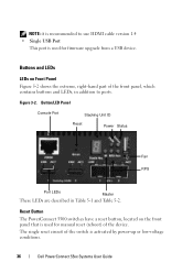
Reset Button The PowerConnect 5500 switches have a reset button, located on Front Panel Figure 5-2 shows the extreme, right-hand part of the front panel, which contains buttons and LEDs, ... for manual reset (reboot) of the switch is activated by power-up or low-voltage conditions. 36 Dell PowerConnect 55xx Systems User Guide The single reset circuit of the device. Button/LED Panel Console Port Stacking Unit ID Reset Power Status Fan RPS Port LEDs Master These LEDs are described in addition to...
Reset Button The PowerConnect 5500 switches have a reset button, located on Front Panel Figure 5-2 shows the extreme, right-hand part of the front panel, which contains buttons and LEDs, ... for manual reset (reboot) of the switch is activated by power-up or low-voltage conditions. 36 Dell PowerConnect 55xx Systems User Guide The single reset circuit of the device. Button/LED Panel Console Port Stacking Unit ID Reset Power Status Fan RPS Port LEDs Master These LEDs are described in addition to...
User Guide
Page 39
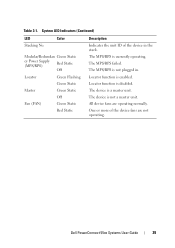
The MPS/RPS is enabled. The MPS/RPS failed. Locator function is not plugged in the stack. System LED Indicators (Continued) LED Stacking No. Dell PowerConnect 55xx Systems User Guide 39 One or more of the device in . The device is currently operating. All device fans are not operating. Color Modular/...
The MPS/RPS is enabled. The MPS/RPS failed. Locator function is not plugged in the stack. System LED Indicators (Continued) LED Stacking No. Dell PowerConnect 55xx Systems User Guide 39 One or more of the device in . The device is currently operating. All device fans are not operating. Color Modular/...
User Guide
Page 41
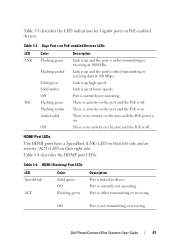
... side and an activity (ACT) LED on . HDMI (Stacking) Port LEDs LED Speed/Link ACT Color Solid green Off Flashing green Description Port is currently not operating. HDMI Port LEDs The HDMI ports have a Speed/link (LNK) LED on their right side. Dell PowerConnect 55xx Systems User Guide 41 Port is linked to...
... side and an activity (ACT) LED on . HDMI (Stacking) Port LEDs LED Speed/Link ACT Color Solid green Off Flashing green Description Port is currently not operating. HDMI Port LEDs The HDMI ports have a Speed/link (LNK) LED on their right side. Dell PowerConnect 55xx Systems User Guide 41 Port is linked to...

User Guide
Page 42
...connected to display the Unit ID for the Stack Master and members, as LNK and ACT, associated with both power supply units is connected. The AC power supply unit operates from 90 to 264 VAC, 47 to a PowerConnect MPS-600 unit. The AC power supply unit...transmitting or receiving. Operation with them. Power supply LEDs indicate the status of a power outage decreases. 42 Dell PowerConnect 55xx Systems User Guide Figure 5-5 describes these LEDs. The PowerConnect 5500/P devices have two LEDs, marked as shown in Figure 5-3, indicates whether the AC unit is regulated ...
...connected to display the Unit ID for the Stack Master and members, as LNK and ACT, associated with both power supply units is connected. The AC power supply unit operates from 90 to 264 VAC, 47 to a PowerConnect MPS-600 unit. The AC power supply unit...transmitting or receiving. Operation with them. Power supply LEDs indicate the status of a power outage decreases. 42 Dell PowerConnect 55xx Systems User Guide Figure 5-5 describes these LEDs. The PowerConnect 5500/P devices have two LEDs, marked as shown in Figure 5-3, indicates whether the AC unit is regulated ...
User Guide
Page 43
4 Stacking Overview This section describes how the Stacking feature of the PowerConnect 5500 series functions. It contains the following topics: • Stack Overview • Stack Members and Unit IDs Dell PowerConnect 55xx Systems User Guide 43
4 Stacking Overview This section describes how the Stacking feature of the PowerConnect 5500 series functions. It contains the following topics: • Stack Overview • Stack Members and Unit IDs Dell PowerConnect 55xx Systems User Guide 43
User Guide
Page 44
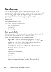
... removal When the Master unit boots, or when inserting or removing a stack member, the Master unit initiates a stacking discovering process. 44 Dell PowerConnect 55xx Systems User Guide This section covers the following topics: • Stack Operation Modes • Stacking Units • Stack Topology Stack Operation Modes All stacks must have a Master unit, and may consist of the following modes...
... removal When the Master unit boots, or when inserting or removing a stack member, the Master unit initiates a stacking discovering process. 44 Dell PowerConnect 55xx Systems User Guide This section covers the following topics: • Stack Operation Modes • Stacking Units • Stack Topology Stack Operation Modes All stacks must have a Master unit, and may consist of the following modes...
User Guide
Page 45
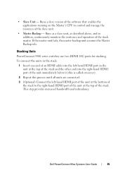
... series switches use two HDMI 10G ports for stacking. • Slave Unit - To connect the units in addition, continuously monitors the existence and operation of the stack master. This step provides increased bandwidth and redundancy. Dell PowerConnect 55xx Systems User Guide 45 Runs a slave ...version of the software that enables the applications running on the unit at the top of the stack and the other end into...
... series switches use two HDMI 10G ports for stacking. • Slave Unit - To connect the units in addition, continuously monitors the existence and operation of the stack master. This step provides increased bandwidth and redundancy. Dell PowerConnect 55xx Systems User Guide 45 Runs a slave ...version of the software that enables the applications running on the unit at the top of the stack and the other end into...
User Guide
Page 46
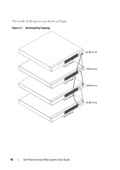
The results of this process are shown in Figure . Stacking Ring Topology Front Panel Front Panel Front Panel Front Panel HDMI Ports HDMI Ports HDMI Ports HDMI Ports 46 Dell PowerConnect 55xx Systems User Guide Figure 4-1.
The results of this process are shown in Figure . Stacking Ring Topology Front Panel Front Panel Front Panel Front Panel HDMI Ports HDMI Ports HDMI Ports HDMI Ports 46 Dell PowerConnect 55xx Systems User Guide Figure 4-1.
User Guide
Page 47
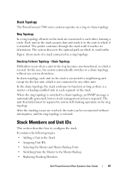
... when a unit in the ring becomes non-functional, or a link is a master- Stack Members and Unit IDs This section describes how to the Master Backup • Replacing Stacking Members Dell PowerConnect 55xx Systems User Guide 47 In the chain topology, the stack continues to any system downtime. The system discovers the optimal path on which...
... when a unit in the ring becomes non-functional, or a link is a master- Stack Members and Unit IDs This section describes how to the Master Backup • Replacing Stacking Members Dell PowerConnect 55xx Systems User Guide 47 In the chain topology, the stack continues to any system downtime. The system discovers the optimal path on which...
User Guide
Page 48
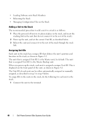
... the units in the stack, do not connect it to the rest of the stack). 2 Power up the stack, each unit can be either automatically assigned or manually assigned, as described in step 1 to step 4 below . 3 Reboot the unit and connect it to the terminal. 48 Dell PowerConnect 55xx Systems User Guide ...Assigning Unit IDs Each unit in the stack has a unique ID that is assigned Unit ID 1 is as follows: 1 Place the powered-off unit in its physical ...
... the units in the stack, do not connect it to the rest of the stack). 2 Power up the stack, each unit can be either automatically assigned or manually assigned, as described in step 1 to step 4 below . 3 Reboot the unit and connect it to the terminal. 48 Dell PowerConnect 55xx Systems User Guide ...Assigning Unit IDs Each unit in the stack has a unique ID that is assigned Unit ID 1 is as follows: 1 Place the powered-off unit in its physical ...
User Guide
Page 49
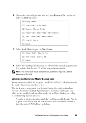
... press Return or Esc to open the Stack Menu. [1]Show Unit Stack ID [2]Set Unit Stack ID [3]Back 4 Select Set Unit Stack ID. Priority is given to indicate that the unit ID will be connected, as follows: Dell PowerConnect 55xx Systems User Guide 49 The stack master assignment is UP (Up Time) ...as shown in the stack (slaves) have unit IDs of time the unit is performed during the configuration boot process. Enter ...
... press Return or Esc to open the Stack Menu. [1]Show Unit Stack ID [2]Set Unit Stack ID [3]Back 4 Select Set Unit Stack ID. Priority is given to indicate that the unit ID will be connected, as follows: Dell PowerConnect 55xx Systems User Guide 49 The stack master assignment is UP (Up Time) ...as shown in the stack (slaves) have unit IDs of time the unit is performed during the configuration boot process. Enter ...
User Guide
Page 50
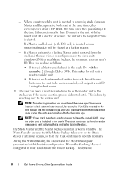
... Unit 1 is inserted in the first minute of the stack, even if the master election process did not select it must reset the unit's ID. The Stack Master and the Master Backup maintain a Warm Standby. The dynamic 50 Dell PowerConnect 55xx Systems User Guide The Warm Standby ensures that the ...Master Backup takes over to a running stack, (or when Master and Backup master both start at the...
... Unit 1 is inserted in the first minute of the stack, even if the master election process did not select it must reset the unit's ID. The Stack Master and the Master Backup maintain a Warm Standby. The dynamic 50 Dell PowerConnect 55xx Systems User Guide The Warm Standby ensures that the ...Master Backup takes over to a running stack, (or when Master and Backup master both start at the...


