
Command Line Interface Guide
Page 158
... use either an ethernet standard cross-over cable to connect to a PC, or an ethernet standard cable to connect to another switch ONLY with a cross cable. • If MDIX is set to half. Console(config)# interface ethernet g5 Console(config-if)# mdix auto back-pressure The... Configuration mode command enables Back Pressure on g5. Console(config)# interface ethernet g5 Console(config-if)# back-pressure 158 Ethernet Configuration Commands User Guidelines • Mdix Auto: All possibilities to connect a PC with cross OR normal cables are supported and are automatically detected. • ...
... use either an ethernet standard cross-over cable to connect to a PC, or an ethernet standard cable to connect to another switch ONLY with a cross cable. • If MDIX is set to half. Console(config)# interface ethernet g5 Console(config-if)# mdix auto back-pressure The... Configuration mode command enables Back Pressure on g5. Console(config)# interface ethernet g5 Console(config-if)# back-pressure 158 Ethernet Configuration Commands User Guidelines • Mdix Auto: All possibilities to connect a PC with cross OR normal cables are supported and are automatically detected. • ...

Command Line Interface Guide
Page 275
... EXEC mode. Syntax • show copper-ports tdr Privileged EXEC mode command display the last TDR (Time Domain Reflectometry) tests on the cable attached to a port. A valid Ethernet port. PHY Diagnostics Commands test copper-port tdr The test copper-port tdr Privileged EXEC mode command... g3. Syntax • test copper-port tdr interface • interface - Default Configuration This command has no default configuration. Console# test copper-port tdr g3 Cable is 120 meters. NOTE: The maximum distance VCT can function is open at 100 meters show copper-ports tdr The show copper...
... EXEC mode. Syntax • show copper-ports tdr Privileged EXEC mode command display the last TDR (Time Domain Reflectometry) tests on the cable attached to a port. A valid Ethernet port. PHY Diagnostics Commands test copper-port tdr The test copper-port tdr Privileged EXEC mode command... g3. Syntax • test copper-port tdr interface • interface - Default Configuration This command has no default configuration. Console# test copper-port tdr g3 Cable is 120 meters. NOTE: The maximum distance VCT can function is open at 100 meters show copper-ports tdr The show copper...

Command Line Interface Guide
Page 276
...configuration. Console# show copper-ports cable-length Privileged EXEC mode command displays the estimated copper cable length attached to a port. Command Mode Privileged EXEC mode. A valid Ethernet port. Example The following example displays the last TDR (Time Domain Reflectometry) tests on all ports. show copper-ports cable-length ... 13:32:00 23 July 2003 - - Default Configuration This command has no default configuration. Syntax • show copper-ports cable-length [interface] • interface - User Guidelines • There are no user guidelines for this command.
...configuration. Console# show copper-ports cable-length Privileged EXEC mode command displays the estimated copper cable length attached to a port. Command Mode Privileged EXEC mode. A valid Ethernet port. Example The following example displays the last TDR (Time Domain Reflectometry) tests on all ports. show copper-ports cable-length ... 13:32:00 23 July 2003 - - Default Configuration This command has no default configuration. Syntax • show copper-ports cable-length [interface] • interface - User Guidelines • There are no user guidelines for this command.

Command Line Interface Guide
Page 277
Example The following example displays the estimated copper cable length attached to all ports. Console# show copper-ports cable-length Port ---g1 g2 g3 Length [meters 50 Giga link not active 110-140 show fiber-ports optical-...transceiver The show fiber-ports optical-transceiver [interface] [detailed] • interface - Detailed diagnostics. User Guidelines • To test optical transceivers, ensure a fiber link is only supported on Dell...
Example The following example displays the estimated copper cable length attached to all ports. Console# show copper-ports cable-length Port ---g1 g2 g3 Length [meters 50 Giga link not active 110-140 show fiber-ports optical-...transceiver The show fiber-ports optical-transceiver [interface] [detailed] • interface - Detailed diagnostics. User Guidelines • To test optical transceivers, ensure a fiber link is only supported on Dell...

User's Guide
Page 25
...a single logical port with the following figure illustrates the PowerConnect 54xx series systems front panel. RS-232 console based port The following ports: • 24/48 Copper ports - Hardware Description 25 PowerConnect 5424 Front Panel The front panel contains ports1-24/48, ...which are designated as 10/100/1000 BaseT Gigabit Ethernet ports • 4 Fiber ports - The device automatically detects whether the cable...
...a single logical port with the following figure illustrates the PowerConnect 54xx series systems front panel. RS-232 console based port The following ports: • 24/48 Copper ports - Hardware Description 25 PowerConnect 5424 Front Panel The front panel contains ports1-24/48, ...which are designated as 10/100/1000 BaseT Gigabit Ethernet ports • 4 Fiber ports - The device automatically detects whether the cable...

User's Guide
Page 26
Figure 2-3. Console Port Combo Ports A combo port is 9600 bps. The default baud rate is a single logical port with two physical connections: • A RJ-45 connection for Twisted Pair copper cabling • A SFP connection for various fiber-based modules Only one time. PowerConnect Back Panel ...operations and control interfaces. 26 Hardware Description Port features and available port controls are two power supply connectors and an RS-232 Console port. Figure 2-2. For general use there is an AC Power Supply connector which is connectable to 38400 bps. The system...
Figure 2-3. Console Port Combo Ports A combo port is 9600 bps. The default baud rate is a single logical port with two physical connections: • A RJ-45 connection for Twisted Pair copper cabling • A SFP connection for various fiber-based modules Only one time. PowerConnect Back Panel ...operations and control interfaces. 26 Hardware Description Port features and available port controls are two power supply connectors and an RS-232 Console port. Figure 2-2. For general use there is an AC Power Supply connector which is connectable to 38400 bps. The system...

User's Guide
Page 34
...keys). 34 Installing the PowerConnect Device The Console port connector is required: • VT100 compatible terminal or a desktop or portable system with a serial port and running VT100 terminal emulation software. • A RS-232 crossover cable with a female DB-9 connector for the Console port and the appropriate ...b Set the data rate to 8 data bits, 1 stop bit, and no parity. To use the Console port, the following : 1 Connect an RS-232 crossover cable to the terminal running terminal emulation software for the terminal. Fasten the lower pair of screws before the upper ...
...keys). 34 Installing the PowerConnect Device The Console port connector is required: • VT100 compatible terminal or a desktop or portable system with a serial port and running VT100 terminal emulation software. • A RS-232 crossover cable with a female DB-9 connector for the Console port and the appropriate ...b Set the data rate to 8 data bits, 1 stop bit, and no parity. To use the Console port, the following : 1 Connect an RS-232 crossover cable to the terminal running terminal emulation software for the terminal. Fasten the lower pair of screws before the upper ...

User's Guide
Page 35
Go to www.microsoft.com for information on the back panel. The device Console port is installed. Figure 3-2. Connecting to PowerConnect 54xx Series Systems Console Port RS-232 Crossover Cable Back Panel Installing the PowerConnect Device 35 With Windows 2000 Service Pack 2, the arrow keys function properly in HyperTerminal's VT100 emulation. CAUTION: When ...® 2000 Service Pack 2 or later is located on Windows 2000 service packs. 3 Connect the female connector of the RS-232 crossover cable directly to the device Console port, and tighten the captive retaining screws.
Go to www.microsoft.com for information on the back panel. The device Console port is installed. Figure 3-2. Connecting to PowerConnect 54xx Series Systems Console Port RS-232 Crossover Cable Back Panel Installing the PowerConnect Device 35 With Windows 2000 Service Pack 2, the arrow keys function properly in HyperTerminal's VT100 emulation. CAUTION: When ...® 2000 Service Pack 2 or later is located on Windows 2000 service packs. 3 Connect the female connector of the RS-232 crossover cable directly to the device Console port, and tighten the captive retaining screws.

User's Guide
Page 40
...and password. When the power is turned on SW emulation are displayed on the terminal and indicate test success or failure. 1 Ensure that the ASCII cable is connected to the terminal, and that the device Serial port is for Terminal keys (not Windows keys). CAUTION: When using HyperTerminal with the ... that Windows® 2000 Service Pack 2 or later is as follows: 1 Select the appropriate serial port (serial port 1 or serial port 2) to connect to the console. 2 Set the data rate to 9600 baud. 3 Set the data format to 8 data bits, 1 stop bit, and no parity. 4 Set flow control to www....
...and password. When the power is turned on SW emulation are displayed on the terminal and indicate test success or failure. 1 Ensure that the ASCII cable is connected to the terminal, and that the device Serial port is for Terminal keys (not Windows keys). CAUTION: When using HyperTerminal with the ... that Windows® 2000 Service Pack 2 or later is as follows: 1 Select the appropriate serial port (serial port 1 or serial port 2) to connect to the console. 2 Set the data rate to 9600 baud. 3 Set the data format to 8 data bits, 1 stop bit, and no parity. 4 Set flow control to www....

User's Guide
Page 142
...view. clear arp-cache Deletes all dynamic entries from the ARP Table. Viewing Copper Cable Diagnostics The Integrated Cable Test for Copper Cables page contains fields for performing virtual cable tests on copper cables. ARP Settings CLI Commands CLI Command Description arp ip_addr hw_addr {ethernet interface- no arp...) technology to test the quality and characteristics of a copper cable attached to a port. Cables are tested when the ports are in the cable, the last time a cable test was performed, and the type of the CLI commands: Console(config)# arp 198.133.219.232 00-00-0c-40-...
...view. clear arp-cache Deletes all dynamic entries from the ARP Table. Viewing Copper Cable Diagnostics The Integrated Cable Test for Copper Cables page contains fields for performing virtual cable tests on copper cables. ARP Settings CLI Commands CLI Command Description arp ip_addr hw_addr {ethernet interface- no arp...) technology to test the quality and characteristics of a copper cable attached to a port. Cables are tested when the ports are in the cable, the last time a cable test was performed, and the type of the CLI commands: Console(config)# arp 198.133.219.232 00-00-0c-40-...

User's Guide
Page 144
... [interface] Shows results of last VCT tests on the Integrated Cable Test for Copper Cables page. 3 Click Test Now. Table 6-28. Performing Copper Cable Tests Using CLI Commands The following is an example of the CLI commands: console> enable Console# test copper-port tdr g3 Cable is performed, and the results are connected to a [interface] port...
... [interface] Shows results of last VCT tests on the Integrated Cable Test for Copper Cables page. 3 Click Test Now. Table 6-28. Performing Copper Cable Tests Using CLI Commands The following is an example of the CLI commands: console> enable Console# test copper-port tdr g3 Cable is performed, and the results are connected to a [interface] port...

User's Guide
Page 427
Port and Cable Specifications This section describes the port specifications. Table 10-1. Port Specifications Device PowerConnect 5400 Port Types RJ-45 SFP Port Settings Specification • 24 GE ports or 48 GE ports • 4 SFP ports • RS-232 Console port • 10 Base-T • 100 Base-T • 1000 Base-T Supports Standard Small Form...
Port and Cable Specifications This section describes the port specifications. Table 10-1. Port Specifications Device PowerConnect 5400 Port Types RJ-45 SFP Port Settings Specification • 24 GE ports or 48 GE ports • 4 SFP ports • RS-232 Console port • 10 Base-T • 100 Base-T • 1000 Base-T Supports Standard Small Form...

User's Guide
Page 441
..., 156- 157 Authentication profiles, 155 Auto-Negotiation, 37 B Back panels, 29 BootP, 432 BPDU, 318, 432 Bridge Protocol Data Unit, 432 Buttons, 61 C Cables, 142, 145 CIDR, 433 Class of Service, 17 CLI, 21 CLI Examples, 66 Command Line Interface, 21 Command Mode Overview, 63 Communities, 210 Community table..., 207 Configuring ARP, 136 Console, 95, 158 CoS, 17, 415 Critical, 95, 104 D DC unit, 29-30 Debug, 95, 104 Default Gateway, 108-109 Default Gateway, IPv6, 120 ...
..., 156- 157 Authentication profiles, 155 Auto-Negotiation, 37 B Back panels, 29 BootP, 432 BPDU, 318, 432 Bridge Protocol Data Unit, 432 Buttons, 61 C Cables, 142, 145 CIDR, 433 Class of Service, 17 CLI, 21 CLI Examples, 66 Command Line Interface, 21 Command Mode Overview, 63 Communities, 210 Community table..., 207 Configuring ARP, 136 Console, 95, 158 CoS, 17, 415 Critical, 95, 104 D DC unit, 29-30 Debug, 95, 104 Default Gateway, 108-109 Default Gateway, IPv6, 120 ...
Getting Started Guide
Page 13
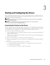
... connector. To connect a terminal to the device Console port, perform the following is described in the Dell™ PowerConnect™ 5400 User's Guide located on the documentation CD. Connecting the Terminal to the Device The device provides a Console port, that enables a connection to the terminal ... recommended that you obtain the most recent revision of the user documentation from http://support.dell.com. To use the Console port, the following : 1 Connect the supplied RS-232 crossover cable to a terminal desktop system running VT100 terminal emulation software. • An RS-232...
... connector. To connect a terminal to the device Console port, perform the following is described in the Dell™ PowerConnect™ 5400 User's Guide located on the documentation CD. Connecting the Terminal to the Device The device provides a Console port, that enables a connection to the terminal ... recommended that you obtain the most recent revision of the user documentation from http://support.dell.com. To use the Console port, the following : 1 Connect the supplied RS-232 crossover cable to a terminal desktop system running VT100 terminal emulation software. • An RS-232...
Getting Started Guide
Page 14
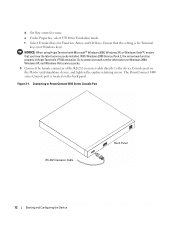
... device, and tighten the captive retaining screws. Figure 3-1. e Under Properties, select VT100 for information on the back panel. d Set flow control to PowerConnect 5400 Series Console Port RS-232 Crossover Cable Back Panel 12 Starting and Configuring the Device NOTICE: When using HyperTerminal with Microsoft® Windows 2000, Windows XP, or Windows Vista...
... device, and tighten the captive retaining screws. Figure 3-1. e Under Properties, select VT100 for information on the back panel. d Set flow control to PowerConnect 5400 Series Console Port RS-232 Crossover Cable Back Panel 12 Starting and Configuring the Device NOTICE: When using HyperTerminal with Microsoft® Windows 2000, Windows XP, or Windows Vista...
Getting Started Guide
Page 15
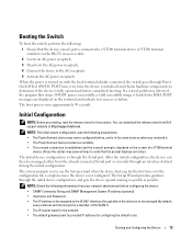
...). If a critical problem is a member of a VT100 terminal device. (Press the key several times to be managed either from Dell support website at http://support.dell.com. POST messages are displayed on the screen of the VLAN 1) • The IP subnet mask for the network • The...RS-232 crossover cable. 2 Locate an AC power receptacle. 3 Deactivate the AC power receptacle. 4 Connect the device to use the Set-up wizard when the device boots up and running as quickly as when you received it. • The PowerConnect device booted successfully. • The console connection is ...
...). If a critical problem is a member of a VT100 terminal device. (Press the key several times to be managed either from Dell support website at http://support.dell.com. POST messages are displayed on the screen of the VLAN 1) • The IP subnet mask for the network • The...RS-232 crossover cable. 2 Locate an AC power receptacle. 3 Deactivate the AC power receptacle. 4 Connect the device to use the Set-up wizard when the device boots up and running as quickly as when you received it. • The PowerConnect device booted successfully. • The console connection is ...


