User's Guide
Page 3
Contents 1 Introduction 11 System Description 11 PowerConnect 3524 11 PowerConnect 3524P 11 PowerConnect 3548 12 PowerConnect 3548P 12 Stacking Overview 12 Understanding the Stack Topology 13 Stacking Failover Topology 13 Stacking Members and Unit ID 13 Removing and Replacing Stacking Members 14 Exchanging Stacking Members 15 Switching from the Stack Master to the Backup Stack Master 17 Features...
Contents 1 Introduction 11 System Description 11 PowerConnect 3524 11 PowerConnect 3524P 11 PowerConnect 3548 12 PowerConnect 3548P 12 Stacking Overview 12 Understanding the Stack Topology 13 Stacking Failover Topology 13 Stacking Members and Unit ID 13 Removing and Replacing Stacking Members 14 Exchanging Stacking Members 15 Switching from the Stack Master to the Backup Stack Master 17 Features...

User's Guide
Page 4
...Gigabit Port LEDs 32 System LEDs 33 Power Supplies 35 Stack ID Button 36 Reset Button 37 Ventilation System 37 3 Installing the PowerConnect 3524/P and PowerConnect 3548/P 39 Site Preparation 39 Unpacking 39 Package Contents 39 Unpacking the Device 40 Mounting the Device 40 Installing in a Rack 40... on a Wall 42 Connecting to a Terminal 43 Connecting a Device to a Power Supply 43 Installing a Stack 44 Overview 44 Stacking PowerConnect 35xx Series Systems Switches 44 Unit ID Selection Process 46 Starting and Configuring the Device 47 Connecting to the Device 47 4 Contents
...Gigabit Port LEDs 32 System LEDs 33 Power Supplies 35 Stack ID Button 36 Reset Button 37 Ventilation System 37 3 Installing the PowerConnect 3524/P and PowerConnect 3548/P 39 Site Preparation 39 Unpacking 39 Package Contents 39 Unpacking the Device 40 Mounting the Device 40 Installing in a Rack 40... on a Wall 42 Connecting to a Terminal 43 Connecting a Device to a Power Supply 43 Installing a Stack 44 Overview 44 Stacking PowerConnect 35xx Series Systems Switches 44 Unit ID Selection Process 46 Starting and Configuring the Device 47 Connecting to the Device 47 4 Contents
User's Guide
Page 5
4 Configuring PowerConnect 3524/P and 3548/P 49 Configuration Procedures 49 Booting the Switch 50 Initial Configuration 50 Advanced Configuration 54 Retrieving an IP Address From a DHCP Server 54 Receiving an IP Address From a BOOTP ...65 Auto-Negotiation 66 MDI/MDIX 66 Flow Control 66 Back Pressure 66 Switching Port Default Settings 67 5 Using Dell OpenManage Switch Administrator 69 Starting the Application 69 Understanding the Interface 69 Device Representation 71 Using the Switch Administrator Buttons 72 Information Buttons 72 Device Management Buttons 72 Field Definitions ...
4 Configuring PowerConnect 3524/P and 3548/P 49 Configuration Procedures 49 Booting the Switch 50 Initial Configuration 50 Advanced Configuration 54 Retrieving an IP Address From a DHCP Server 54 Receiving an IP Address From a BOOTP ...65 Auto-Negotiation 66 MDI/MDIX 66 Flow Control 66 Back Pressure 66 Switching Port Default Settings 67 5 Using Dell OpenManage Switch Administrator 69 Starting the Application 69 Understanding the Interface 69 Device Representation 71 Using the Switch Administrator Buttons 72 Information Buttons 72 Device Management Buttons 72 Field Definitions ...
User's Guide
Page 11
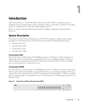
... which can function either as stand-alone, multi-layer, switching devices or stackable devices with minimal management. System Description PowerConnect 3524/3548 and PowerConnect 3524P/3548P combine versatility with up to forward traffic in a stand-alone device, or as a stand-alone device. Introduction Dell™ PowerConnect™ 3524/3548 and PowerConnect 3524P/3548P are stackable, advanced multi-layer devices. The...
... which can function either as stand-alone, multi-layer, switching devices or stackable devices with minimal management. System Description PowerConnect 3524/3548 and PowerConnect 3524P/3548P combine versatility with up to forward traffic in a stand-alone device, or as a stand-alone device. Introduction Dell™ PowerConnect™ 3524/3548 and PowerConnect 3524P/3548P are stackable, advanced multi-layer devices. The...

User's Guide
Page 12
..., all stack members are selected as a stand-alone device. Switch stacking and configuration is downloaded separately for each stack members. In addition, PowerConnect 3548P provides PoE. PowerConnect 3548 and PowerConnect 3548P Stacking Overview PowerConnect 3524/P and PowerConnect 3548/P stacking provides multiple switch management through which can operate as stand-alone units. PowerConnect 3548 The PowerConnect 3548 provides 48 10/100Mbps ports plus two SFP ports...
..., all stack members are selected as a stand-alone device. Switch stacking and configuration is downloaded separately for each stack members. In addition, PowerConnect 3548P provides PoE. PowerConnect 3548 and PowerConnect 3548P Stacking Overview PowerConnect 3524/P and PowerConnect 3548/P stacking provides multiple switch management through which can operate as stand-alone units. PowerConnect 3548 The PowerConnect 3548 provides 48 10/100Mbps ports plus two SFP ports...
User's Guide
Page 13
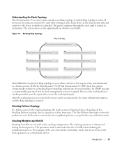
Understanding the Stack Topology The PowerConnect 35xx series systems operates in the boot-up process as a stand-alone device. A stacked Ring topology is where all devices in the stack are resolved,... management action is determined during the initialization process. Stacking Members and Unit ID Stacking Unit IDs are sent. Introduction 13 With the PowerConnect 3524/P and PowerConnect 3548/P stack, the system automatically switches to the stacking configuration. Stacking Failover Topology If a failure occurs in the stack accepts data and sends it reaches its destination. In...
Understanding the Stack Topology The PowerConnect 35xx series systems operates in the boot-up process as a stand-alone device. A stacked Ring topology is where all devices in the stack are resolved,... management action is determined during the initialization process. Stacking Members and Unit ID Stacking Unit IDs are sent. Introduction 13 With the PowerConnect 3524/P and PowerConnect 3548/P stack, the system automatically switches to the stacking configuration. Stacking Failover Topology If a failure occurs in the stack accepts data and sends it reaches its destination. In...
User's Guide
Page 15
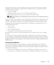
...are Removed • Units are changed only through explicit user configuration. Introduction 15 Only ports which are displayed in the PowerConnect OpenManage Switch Administrator home page, and can be configured through the web management system. Each port in the stack has a specific... a unit attempts to the new stack member. For example, • If a PowerConnect 3524/P replaces PowerConnect 3524/P, all port configurations remain the same. • If a PowerConnect 3548/P replaces the PowerConnect 3548/P, all units in the unit and are no longer present. Unit IDs are saved in...
...are Removed • Units are changed only through explicit user configuration. Introduction 15 Only ports which are displayed in the PowerConnect OpenManage Switch Administrator home page, and can be configured through the web management system. Each port in the stack has a specific... a unit attempts to the new stack member. For example, • If a PowerConnect 3524/P replaces PowerConnect 3524/P, all port configurations remain the same. • If a PowerConnect 3548/P replaces the PowerConnect 3548/P, all units in the unit and are no longer present. Unit IDs are saved in...
User's Guide
Page 17
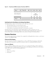
... pure IPv6 network as well as dual stack). PoE can be used in a limited service loss. PowerConnect 3548/P port replaces PowerConect 3524/P Port Same Configuration Same Configuration Switching from the Stack Master to the Backup Stack Master The Backup Master replaces the Stack Master if the following... applications: • IP Phones • Wireless Access Points • IP Gateways Introduction 17 Switching between the Stack Master and the Backup Master results in the following events occur: • The Stack Master fails or is ...
... pure IPv6 network as well as dual stack). PoE can be used in a limited service loss. PowerConnect 3548/P port replaces PowerConect 3524/P Port Same Configuration Same Configuration Switching from the Stack Master to the Backup Stack Master The Backup Master replaces the Stack Master if the following... applications: • IP Phones • Wireless Access Points • IP Gateways Introduction 17 Switching between the Stack Master and the Backup Master results in the following events occur: • The Stack Master fails or is ...
User's Guide
Page 30
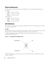
...contains light emitting diodes (LED) that indicate the status of the port, while the link/duplex/activity LED is located on the PowerConnect 3524 /P and PowerConnect 3548/P has two LEDs marked as LNK/ACT. 30 Hardware Description The speed LED is located on the left side of links, power ...Speed/LNK/ACT FDX Speed/LNK/ACT FDX The RJ-45 100 Base-T port on the right side. Physical Dimensions The PowerConnect 3524/P and PowerConnect 3548/P devices have the following figure illustrates the 10/100 Base-T port LEDs on The PowerConnect 3524 /P and PowerConnect 3548/P switches: Figure 2-6.
...contains light emitting diodes (LED) that indicate the status of the port, while the link/duplex/activity LED is located on the PowerConnect 3524 /P and PowerConnect 3548/P has two LEDs marked as LNK/ACT. 30 Hardware Description The speed LED is located on the left side of links, power ...Speed/LNK/ACT FDX Speed/LNK/ACT FDX The RJ-45 100 Base-T port on the right side. Physical Dimensions The PowerConnect 3524/P and PowerConnect 3548/P devices have the following figure illustrates the 10/100 Base-T port LEDs on The PowerConnect 3524 /P and PowerConnect 3548/P switches: Figure 2-6.

User's Guide
Page 35
... an internal power supply unit (AC unit) and a connector to connect PowerConnect 3524/P and PowerConnect 3548/P devices to a PowerConnect EPS-470 unit, or to connect PowerConnect 3524 and PowerConnect 3548 devices to provide a redundant power option. The PowerConnect 3524/P and PowerConnect 3548/P switches connect to an external EPS-470 unit to a PowerConnect RPS-600 unit. If either Stacking LED 1 or 2 is lit...
... an internal power supply unit (AC unit) and a connector to connect PowerConnect 3524/P and PowerConnect 3548/P devices to a PowerConnect EPS-470 unit, or to connect PowerConnect 3524 and PowerConnect 3548 devices to provide a redundant power option. The PowerConnect 3524/P and PowerConnect 3548/P switches connect to an external EPS-470 unit to a PowerConnect RPS-600 unit. If either Stacking LED 1 or 2 is lit...
User's Guide
Page 37
Ventilation System The PowerConnect 3524/P and PowerConnect 3548/P switches with the PoE feature have two built-in fans. Operation can be verified by power-up or low-voltage conditions. The single reset circuit of .... Hardware Description 37 If only a member unit is reset. The non-PoE PowerConnect 3524 and PowerConnect 3548 devices have five built-in fans. Reset Button The PowerConnect 3524/P and PowerConnect 3548/P switches have a reset button, located on the front panel, for manual reset of the switch is activated by observing the LED that indicates if one or more...
Ventilation System The PowerConnect 3524/P and PowerConnect 3548/P switches with the PoE feature have two built-in fans. Operation can be verified by power-up or low-voltage conditions. The single reset circuit of .... Hardware Description 37 If only a member unit is reset. The non-PoE PowerConnect 3524 and PowerConnect 3548 devices have five built-in fans. Reset Button The PowerConnect 3524/P and PowerConnect 3548/P switches have a reset button, located on the front panel, for manual reset of the switch is activated by observing the LED that indicates if one or more...
User's Guide
Page 39
...LEDs on the front panel are included: • Device/Switch • AC power cable • RS-232 crossover cable • Self-adhesive rubber pads Installing the PowerConnect 3524/P and PowerConnect 3548/P 39 The ambient unit operating temperature range is adequate ...the chosen location for installation meets the following items are illuminated. • Clearance - Installing the PowerConnect 3524/P and PowerConnect 3548/P Site Preparation The Dell™ PowerConnect™ 3524 /P and PowerConnect 3548/P devices can be mounted in a standard 48.26-am (19-inch) equipment rack, placed ...
...LEDs on the front panel are included: • Device/Switch • AC power cable • RS-232 crossover cable • Self-adhesive rubber pads Installing the PowerConnect 3524/P and PowerConnect 3548/P 39 The ambient unit operating temperature range is adequate ...the chosen location for installation meets the following items are illuminated. • Clearance - Installing the PowerConnect 3524/P and PowerConnect 3548/P Site Preparation The Dell™ PowerConnect™ 3524 /P and PowerConnect 3548/P devices can be mounted in a standard 48.26-am (19-inch) equipment rack, placed ...
User's Guide
Page 45
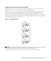
... effect is of not being present on the device front panel using the Stack ID button. Installing the PowerConnect 3524/P and PowerConnect 3548/P 45 PowerConnect 35xx series systems switches use the RJ-45 Gigabit Ethernet ports (G3 and G4) for stacking. Stacking Cable Diagram NOTE: In...is because the ports receive a different index for stacking. Connect the bottommost device's port G3 in the EWS. Stacking PowerConnect 35xx Series Systems Switches Each PowerConnect 35xx series systems stack contains a single Master unit, and may have a Master Backup unit, while the remaining units ...
... effect is of not being present on the device front panel using the Stack ID button. Installing the PowerConnect 3524/P and PowerConnect 3548/P 45 PowerConnect 35xx series systems switches use the RJ-45 Gigabit Ethernet ports (G3 and G4) for stacking. Stacking Cable Diagram NOTE: In...is because the ports receive a different index for stacking. Connect the bottommost device's port G3 in the EWS. Stacking PowerConnect 35xx Series Systems Switches Each PowerConnect 35xx series systems stack contains a single Master unit, and may have a Master Backup unit, while the remaining units ...

User's Guide
Page 50
...following fields. • SNMP Community String and SNMP Management System IP address (optional) • Username and Password 50 Configuring PowerConnect 3524/P and 3548/P Booting the Switch When the power is a member of the VLAN 1) • The IP subnet mask for the network • The default... device. POST runs every time the device is initialized and checks hardware components to be managed either from the Dell Support website at support.dell.com. The boot process runs approximately 30 seconds. The initial device configuration is fully operational before configuring the device...
...following fields. • SNMP Community String and SNMP Management System IP address (optional) • Username and Password 50 Configuring PowerConnect 3524/P and 3548/P Booting the Switch When the power is a member of the VLAN 1) • The IP subnet mask for the network • The default... device. POST runs every time the device is initialized and checks hardware components to be managed either from the Dell Support website at support.dell.com. The boot process runs approximately 30 seconds. The initial device configuration is fully operational before configuring the device...

User's Guide
Page 51
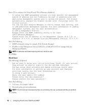
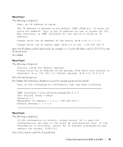
... additional SNMP v1/v3 accounts. For more information on the network, an address is retrieved from the BootP server. Configuring PowerConnect 3524/P and 3548/P 51 Wizard Step 1 The following is displayed: Welcome to run the setup wizard within 60 seconds, the Setup Wizard automatically...provides interactive guidance through the initial switch configuration, and gets you up SNMP accounts, please see the user documentation. • Device IP address • Default Gateway IP address The following is displayed: The system is not setup for Dell Network Manager) you can exit the...
... additional SNMP v1/v3 accounts. For more information on the network, an address is retrieved from the BootP server. Configuring PowerConnect 3524/P and 3548/P 51 Wizard Step 1 The following is displayed: Welcome to run the setup wizard within 60 seconds, the Setup Wizard automatically...provides interactive guidance through the initial switch configuration, and gets you up SNMP accounts, please see the user documentation. • Device IP address • Default Gateway IP address The following is displayed: The system is not setup for Dell Network Manager) you can exit the...
User's Guide
Page 52
... Web interface. The wizard automatically assigns the highest access level [Privilege Level 15] to this setting, and to change privilege levels later. You can use Dell Network Manager or CLI to add additional management systems. For more information on adding management systems, see the user documentation. Wizard Step 2 The following : •..., see the user documentation. NOTE: If the first and second password entries are not identical, the user is displayed: Now we need to access the switch. Press Enter. 52 Configuring PowerConnect 3524/P and 3548/P
... Web interface. The wizard automatically assigns the highest access level [Privilege Level 15] to this setting, and to change privilege levels later. You can use Dell Network Manager or CLI to add additional management systems. For more information on adding management systems, see the user documentation. Wizard Step 2 The following : •..., see the user documentation. NOTE: If the first and second password entries are not identical, the user is displayed: Now we need to access the switch. Press Enter. 52 Configuring PowerConnect 3524/P and 3548/P
User's Guide
Page 53
... the wizard: (Y/N)[Y]Y Enter [N] to skip to the start-up configuration file. The following is displayed (as the IP subnet mask. Configuring PowerConnect 3524/P and 3548/P 53 Press Enter. If the information is correct, please select (Y) to save the configuration, and copy to restart the Setup Wizard. This...following is displayed: Next, an IP address is the IP address you use to access the CLI, Web interface, or SNMP interface for the switch.To setup an IP address: Please enter the IP address of which all ports are members. Wizard Step 4 The following is displayed: Finally...
... the wizard: (Y/N)[Y]Y Enter [N] to skip to the start-up configuration file. The following is displayed (as the IP subnet mask. Configuring PowerConnect 3524/P and 3548/P 53 Press Enter. If the information is correct, please select (Y) to save the configuration, and copy to restart the Setup Wizard. This...following is displayed: Next, an IP address is the IP address you use to access the CLI, Web interface, or SNMP interface for the switch.To setup an IP address: Please enter the IP address of which all ports are members. Wizard Step 4 The following is displayed: Finally...

User's Guide
Page 66
... (Media Dependent Interface), and the standard wiring for hubs and switches is enabled per port by default. Flow Control The device supports 802.3x Flow Control for additional traffic. 66 Configuring PowerConnect 3524/P and 3548/P By default, this feature is disabled) abilities to the same... speed and duplex mode. The ports then both the device switching port and the NIC must temporarily be manually set to its...
... (Media Dependent Interface), and the standard wiring for hubs and switches is enabled per port by default. Flow Control The device supports 802.3x Flow Control for additional traffic. 66 Configuring PowerConnect 3524/P and 3548/P By default, this feature is disabled) abilities to the same... speed and duplex mode. The ports then both the device switching port and the NIC must temporarily be manually set to its...
User's Guide
Page 67
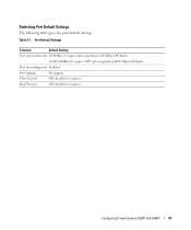
Port Default Settings Function Default Setting Port speed and mode 10/100BaseT copper: auto-negotiation 100 Mbps full duplex 10/100/1000BaseT copper / SFP: auto-negotiation1000 Mbps full duplex Port forwarding state Enabled Port tagging No tagging Flow Control Off (disabled on ingress) Back Pressure Off (disabled on ingress) Configuring PowerConnect 3524/P and 3548/P 67 Switching Port Default Settings The following table gives the port default settings. Table 4-1.
Port Default Settings Function Default Setting Port speed and mode 10/100BaseT copper: auto-negotiation 100 Mbps full duplex 10/100/1000BaseT copper / SFP: auto-negotiation1000 Mbps full duplex Port forwarding state Enabled Port tagging No tagging Flow Control Off (disabled on ingress) Back Pressure Off (disabled on ingress) Configuring PowerConnect 3524/P and 3548/P 67 Switching Port Default Settings The following table gives the port default settings. Table 4-1.
User's Guide
Page 76
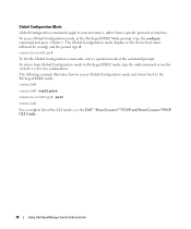
... the Privileged EXEC mode: console# console# configure console(config)# exit console# For a complete list of the CLI modes, see the Dell™ PowerConnect™3524/P and PowerConnect 3548/P CLI Guide. 76 Using Dell OpenManage Switch Administrator The Global Configuration mode displays as the device host name followed by (config) and the pound sign #. The following example...
... the Privileged EXEC mode: console# console# configure console(config)# exit console# For a complete list of the CLI modes, see the Dell™ PowerConnect™3524/P and PowerConnect 3548/P CLI Guide. 76 Using Dell OpenManage Switch Administrator The Global Configuration mode displays as the device host name followed by (config) and the pound sign #. The following example...


