Dell PowerConnect 3548 Support Question
Dell PowerConnect 3548 Support Question
Find answers below for this question about Dell PowerConnect 3548.Need a Dell PowerConnect 3548 manual? We have 3 online manuals for this item!
Question posted by joelMa on January 26th, 2014
How To Preform A Factory Reset On A Dell Powerconnect 3548 Switch
The person who posted this question about this Dell product did not include a detailed explanation. Please use the "Request More Information" button to the right if more details would help you to answer this question.
Current Answers
Related Dell PowerConnect 3548 Manual Pages
Command Line Interface Guide - Page 29

... device has a defined IP address, corresponding management access is granted, and the workstation used to allow traffic based on MAC addresses.
For more information, see Dell™ PowerConnect™ 3500 Series User's Guide.
2 Enter the following steps are for Terminal
keys (not Windows keys). The device is very similar to manually specify...
User's Guide - Page 3
Contents
1 Introduction 11
System Description 11 PowerConnect 3524 11 PowerConnect 3524P 11 PowerConnect 3548 12 PowerConnect 3548P 12
Stacking Overview 12 Understanding the Stack Topology 13 Stacking Failover Topology 13 Stacking Members and Unit ID 13 Removing and Replacing Stacking Members 14 Exchanging Stacking Members 15 Switching from the Stack Master to the Backup Stack Master ...
User's Guide - Page 4

...LEDs 33 Power Supplies 35 Stack ID Button 36 Reset Button 37 Ventilation System 37
3 Installing the PowerConnect 3524/P and PowerConnect 3548/P 39
Site Preparation 39
Unpacking 39 Package Contents...Power Supply 43
Installing a Stack 44 Overview 44 Stacking PowerConnect 35xx Series Systems Switches 44 Unit ID Selection Process 46
Starting and Configuring the Device 47 Connecting to the...
User's Guide - Page 11
... to eight stacking members.
Introduction
Dell™ PowerConnect™ 3524/3548 and PowerConnect 3524P/3548P are stackable, advanced multi-layer devices. The PowerConnect 3524 and 3548 series include the following device types: • PowerConnect 3524 • PowerConnect 3524P • PowerConnect 3548 • PowerConnect 3548P
PowerConnect 3524
The PowerConnect 3524 provides 24 10...
User's Guide - Page 15
... and port number, which are physically present are displayed in the PowerConnect OpenManage Switch Administrator home page, and can be configured through topology discovery. If... PowerConnect 3524/P replaces PowerConnect 3524/P, all port configurations remain the same.
• If a PowerConnect 3548/P replaces the PowerConnect 3548/P, all configured ports is saved, even if the stack is reset ...
User's Guide - Page 27
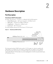
.../100Base-T ports • 2 Fiber ports - PowerConnect 3524 Front Panel
10/100 Base-T Ports 1, 3, 5, 7, ...23
System LEDs Reset Button Stacking Button Stacking LEDs
10/100 Base-T Ports...Hardware Description
Port Description
PowerConnect 3524 Port Description
The Dell™ PowerConnect™ 3524 device is marked with the following figure illustrates the PowerConnect 3524 front panel. RS...
User's Guide - Page 28
... • Console port - RS-232 Console based port The following figure illustrates the PowerConnect 3524 back:
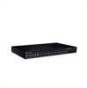
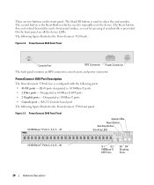
Figure 2-2. PowerConnect 3548 Port Description
The PowerConnect 3548 device is used to select the unit number. PowerConnect 3548 Front Panel 10/100 Base-T Ports 1, 3, 5, 7, ...47
System LEDs Reset Button Stacking Button Stacking LEDs
10/100 Base-T Ports 2, 4, 6, 8, ...48
G1 G2...
User's Guide - Page 29
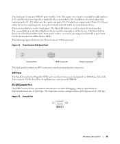
... RPS connector, console port and power connector. There are copper ports. The following figure illustrates the PowerConnect 3548 back panel:
Figure 2-4. Console Port
Hardware Description
29 Ports G3-
The default baud rate is used to manually reset the device. Figure 2-5.
On the front panel are fiber transceivers designated as stacking ports, or used...
User's Guide - Page 30
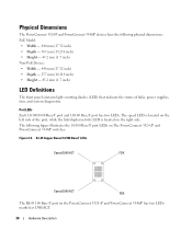
...have the following figure illustrates the 10/100 Base-T port LEDs on The PowerConnect 3524 /P and PowerConnect 3548/P switches:
Figure 2-6. The speed LED is located on the right side. The ...the status of the port, while the link/duplex/activity LED is located on the PowerConnect 3524 /P and PowerConnect 3548/P has two LEDs marked as LNK/ACT.
30
Hardware Description RJ-45 Copper Based...
User's Guide - Page 35

... power supply unit operates from 90 to 264 VAC, 47 to provide a redundant power option. The PowerConnect 3524/P and PowerConnect 3548/P switches connect to an external EPS-470 unit to 63 Hz. Hardware Description
35 The PowerConnect 3524/P and PowerConnect 3548/P devices have an internal power supply (12 Volt). LED indicator is on the front panel and...
User's Guide - Page 37
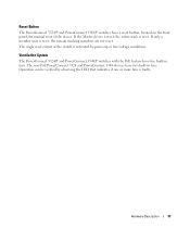
... feature have five built-in fans. Operation can be verified by power-up or low-voltage conditions. The non-PoE PowerConnect 3524 and PowerConnect 3548 devices have a reset button, located on the front panel, for manual reset of the switch is reset.
If only a member unit is faulty. Reset Button
The PowerConnect 3524/P and PowerConnect 3548/P switches have two built-in fans.
User's Guide - Page 39
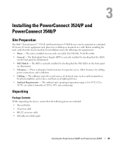
Installing the PowerConnect 3524/P and PowerConnect 3548/P
Site Preparation
The Dell™ PowerConnect™ 3524 /P and PowerConnect 3548/P devices can be mounted in a ... items are included: • Device/Switch • AC power cable • RS-232 crossover cable • Self-adhesive rubber pads
Installing the PowerConnect 3524/P and PowerConnect 3548/P
39 The cabling is 0 to 45...
User's Guide - Page 47
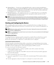
... device to the LED ID flashing at the end of the user documentation from the Dell Support website at a time will allow for sufficient time to 1. Performing the additional ... terminal equipment (DTE) connector.
Unit 1 and Unit 2 are selected. Installing the PowerConnect 3524/P and PowerConnect 3548/P
47 NOTE: These steps should be connected to be cabled as per the "Stacking...
User's Guide - Page 50

... Management System IP address (optional)
• Username and Password
50
Configuring PowerConnect 3524/P and 3548/P If this product. The Setup Wizard provides guidance through the initial device ...Switch
When the power is loaded into RAM. The initial device configuration is in the same state as possible. The Setup Wizard configures the following :
• The Dell™ PowerConnect...
User's Guide - Page 71
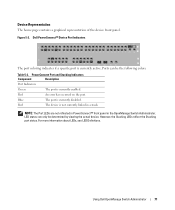
... device.
Dell PowerConnect™ Device Port Indicators
The port coloring indicates if a specific port is currently enabled. Ports can only be the following colors:
Table 5-2.
PowerConnect Port and Stacking Indicators
Component
Description
Port Indicators
Green
The port is currently active. Blue
The port is not currently linked in the OpenManage Switch Administrator...
User's Guide - Page 76
... the Privileged EXEC mode: console#
console# configure
console(config)# exit
console#
For a complete list of the CLI modes, see the Dell™ PowerConnect™3524/P and PowerConnect 3548/P CLI Guide.
76
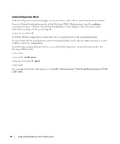
Using Dell OpenManage Switch Administrator console(config)#
To list the Global Configuration commands, enter a question mark at the Privileged EXEC Mode prompt, type the configure...
User's Guide - Page 249
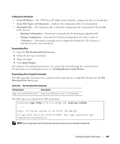
...: Each exclamation mark (!) indicates that ten packets were successfully transferred. Downloads the Startup Configuration file, and overwrites it. - - For information on resetting the device, see Switching Between Stack Masters.
Downloads commands into a configuration backup file. Downloads commands into the Running Configuration file. -
Table 6-53. Indicates the configuration files...
Getting Started Guide - Page 7

... series switches. The unit is correctly installed by checking that the LEDs on the front panel ( For PoE models) are illuminated. • LEDs on documentation and software. The ambient unit operating temperature range is available on the front panel are illuminated. • Clearance - Installation
5 For more information, see the Dell™ PowerConnect™...
Getting Started Guide - Page 14

Figure 2-1. Stacking Cable Diagram
For more information on stacking, see the Dell PowerConnect 3500 Series User's Guide on the device front-panel using the Stack ID button.
12
Stacking You can perform the stack unit identification on the Documentation CD.
Getting Started Guide - Page 17

...switch.
You can download the release
notes from the Dell Support website at support.dell.com. The Console port connector is a male DB-9 connector, implemented as a single device, only the Master unit is configured. Performing the additional advanced functions are described in the Dell PowerConnect... the most recent revision of the user documentation
from the Dell Support website at support...


