
User's Guide
Page 4
... Console Port 29 Physical Dimensions 30 LED Definitions 30 Gigabit Port LEDs 32 System LEDs 33 Power Supplies 35 Stack ID Button 36 Reset Button 37 Ventilation System 37 3 Installing the PowerConnect 3524/P and PowerConnect 3548/P 39 Site Preparation 39 Unpacking 39 Package Contents 39 Unpacking the Device 40 Mounting the Device 40 Installing in a Rack...
... Console Port 29 Physical Dimensions 30 LED Definitions 30 Gigabit Port LEDs 32 System LEDs 33 Power Supplies 35 Stack ID Button 36 Reset Button 37 Ventilation System 37 3 Installing the PowerConnect 3524/P and PowerConnect 3548/P 39 Site Preparation 39 Unpacking 39 Package Contents 39 Unpacking the Device 40 Mounting the Device 40 Installing in a Rack...
User's Guide
Page 27
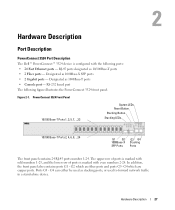
.../100Base-T ports • 2 Fiber ports - G2 which are fiber ports and ports G3- PowerConnect 3524 Front Panel 10/100 Base-T Ports 1, 3, 5, 7, ...23 System LEDs Reset Button Stacking Button Stacking LEDs 10/100 Base-T Ports 2, 4, 6, 8, ...24 G1 G2 1000Base-X SFP Ports... G3 G4 Stacking Ports The front panel contains 24 RJ-45 ports number 1-24. Hardware Description Port Description PowerConnect 3524 Port Description The Dell™ PowerConnect™...
.../100Base-T ports • 2 Fiber ports - G2 which are fiber ports and ports G3- PowerConnect 3524 Front Panel 10/100 Base-T Ports 1, 3, 5, 7, ...23 System LEDs Reset Button Stacking Button Stacking LEDs 10/100 Base-T Ports 2, 4, 6, 8, ...24 G1 G2 1000Base-X SFP Ports... G3 G4 Stacking Ports The front panel contains 24 RJ-45 ports number 1-24. Hardware Description Port Description PowerConnect 3524 Port Description The Dell™ PowerConnect™...
User's Guide
Page 28
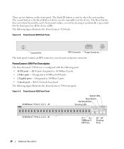
...console port, and power connector. Designated as 1000Base-T ports • Console port - The second button is the Reset Button which is configured with the following figure illustrates the PowerConnect 3548 front panel. RJ-45 ports designated as 10/100Base-T ports • 2 Fiber ports -... Figure 2-3. On the front panel are two buttons on the front panel. PowerConnect 3548 Front Panel 10/100 Base-T Ports 1, 3, 5, 7, ...47 System LEDs Reset Button Stacking Button Stacking LEDs 10/100 Base-T Ports 2, 4, 6, 8, ...48 G1 G2 1000Base-X SFP ...
...console port, and power connector. Designated as 1000Base-T ports • Console port - The second button is the Reset Button which is configured with the following figure illustrates the PowerConnect 3548 front panel. RJ-45 ports designated as 10/100Base-T ports • 2 Fiber ports -... Figure 2-3. On the front panel are two buttons on the front panel. PowerConnect 3548 Front Panel 10/100 Base-T Ports 1, 3, 5, 7, ...47 System LEDs Reset Button Stacking Button Stacking LEDs 10/100 Base-T Ports 2, 4, 6, 8, ...48 G1 G2 1000Base-X SFP ...
User's Guide
Page 29
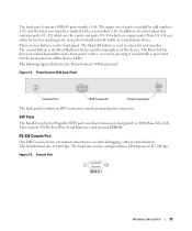
G4 can be used to forward network traffic in a stand-alone device. The second button is the Reset Button which are fiber ports and ports G3- PowerConnect 3548 Back Panel Console Port RPS Connector Power Connector The back panel contains an RPS connector, console port and power ...with even numbers 2-48. The default baud rate is prevented. The following figure illustrates the PowerConnect 3548 back panel: Figure 2-4. The Reset button does not extend beyond the unit's front panel surface, so reset by odd numbers 1-47, and the lower row of ports is marked by pressing it ...
G4 can be used to forward network traffic in a stand-alone device. The second button is the Reset Button which are fiber ports and ports G3- PowerConnect 3548 Back Panel Console Port RPS Connector Power Connector The back panel contains an RPS connector, console port and power ...with even numbers 2-48. The default baud rate is prevented. The following figure illustrates the PowerConnect 3548 back panel: Figure 2-4. The Reset button does not extend beyond the unit's front panel surface, so reset by odd numbers 1-47, and the lower row of ports is marked by pressing it ...
User's Guide
Page 37
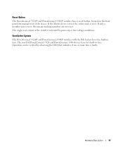
... can be verified by power-up or low-voltage conditions. Ventilation System The PowerConnect 3524/P and PowerConnect 3548/P switches with the PoE feature have two built-in fans. Reset Button The PowerConnect 3524/P and PowerConnect 3548/P switches have a reset button, located on the front panel, for manual reset of the switch is activated by observing the LED that indicates if one...
... can be verified by power-up or low-voltage conditions. Ventilation System The PowerConnect 3524/P and PowerConnect 3548/P switches with the PoE feature have two built-in fans. Reset Button The PowerConnect 3524/P and PowerConnect 3548/P switches have a reset button, located on the front panel, for manual reset of the switch is activated by observing the LED that indicates if one...
User's Guide
Page 72
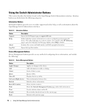
... interfaces. For example, if the IP Addressing page is clicked. Contains the version and build number and Dell copyright information. Device Management Buttons Button Apply Changes Add Telnet Query Show All Left arrow/Right Arrows Refresh Reset All Counters Print Draw Details Back Description Applies set changes to the current page. Adds information to...
... interfaces. For example, if the IP Addressing page is clicked. Contains the version and build number and Dell copyright information. Device Management Buttons Button Apply Changes Add Telnet Query Show All Left arrow/Right Arrows Refresh Reset All Counters Print Draw Details Back Description Applies set changes to the current page. Adds information to...

User's Guide
Page 473
In User Service, 462 Remote Authorization Dial-In User Service, 200 Reset, 128 Reset button, 37 RMON, 420, 422-423, 425, 462 RMON History Control Page, 423 RPS, 35 RSTP, 22, 339, 463 Rule, 175 Rules, 170 Running Configuration file, ...
In User Service, 462 Remote Authorization Dial-In User Service, 200 Reset, 128 Reset button, 37 RMON, 420, 422-423, 425, 462 RMON History Control Page, 423 RPS, 35 RSTP, 22, 339, 463 Rule, 175 Rules, 170 Running Configuration file, ...


