User's Guide
Page 3
Contents 1 Introduction 11 System Description 11 PowerConnect 3524 11 PowerConnect 3524P 11 PowerConnect 3548 12 PowerConnect 3548P 12 Stacking Overview 12 Understanding the Stack Topology 13 Stacking Failover Topology 13 Stacking Members and Unit... ID 13 Removing and Replacing Stacking Members 14 Exchanging Stacking Members 15 Switching from the Stack Master to the Backup Stack Master 17 Features Overview 17 IP Version 6 (IPv6) Support 17 Power...
Contents 1 Introduction 11 System Description 11 PowerConnect 3524 11 PowerConnect 3524P 11 PowerConnect 3548 12 PowerConnect 3548P 12 Stacking Overview 12 Understanding the Stack Topology 13 Stacking Failover Topology 13 Stacking Members and Unit... ID 13 Removing and Replacing Stacking Members 14 Exchanging Stacking Members 15 Switching from the Stack Master to the Backup Stack Master 17 Features Overview 17 IP Version 6 (IPv6) Support 17 Power...
User's Guide
Page 11
... a stand-alone device, or as a stand-alone device. Introduction Dell™ PowerConnect™ 3524/3548 and PowerConnect 3524P/3548P are stackable, advanced multi-layer devices. Figure 1-1. This User Guide contains the information needed for installing, configuring, and maintaining the device. The PowerConnect 3524P also provides Power over Ethernet (PoE). PowerConnect units can be used to forward traffic in a stand...
... a stand-alone device, or as a stand-alone device. Introduction Dell™ PowerConnect™ 3524/3548 and PowerConnect 3524P/3548P are stackable, advanced multi-layer devices. Figure 1-1. This User Guide contains the information needed for installing, configuring, and maintaining the device. The PowerConnect 3524P also provides Power over Ethernet (PoE). PowerConnect units can be used to forward traffic in a stand...
User's Guide
Page 32
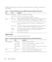
.... The port is either transmitting or receiving data at 10 or 100Mbs. OFF No powered device is running at 10 or 100 Mbps. PowerConnect 3524 and PowerConnect 3548 RJ-45 Copper based 100BaseT LED Indications LED Link/Activity/Speed FDX Color Green ...Green Flashing The ports is currently linked at normal load. For more information about Powered Devices, see "Managing Power over Ethernet". Gigabit Port LEDs The following table: Table 2-2. PowerConnect 3524P and PowerConnect 3548P RJ-45 Copper based 100BaseT LED Indications LED Color Description Speed/Link/Act ...
.... The port is either transmitting or receiving data at 10 or 100Mbs. OFF No powered device is running at 10 or 100 Mbps. PowerConnect 3524 and PowerConnect 3548 RJ-45 Copper based 100BaseT LED Indications LED Link/Activity/Speed FDX Color Green ...Green Flashing The ports is currently linked at normal load. For more information about Powered Devices, see "Managing Power over Ethernet". Gigabit Port LEDs The following table: Table 2-2. PowerConnect 3524P and PowerConnect 3548P RJ-45 Copper based 100BaseT LED Indications LED Color Description Speed/Link/Act ...
User's Guide
Page 44
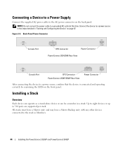
... in a stack. Figure 3-4. Installing a Stack Overview Each device can operate as Members. 44 Installing the PowerConnect 3524/P and PowerConnect 3548/P Back-Panel Power Connector Console Port RPS Connector Power Connector PowerConnect 3524/3548 Rear View Console Port EPS Connector PowerConnect 3524P/3548P Rear View Power Connector After connecting the device to 384 ports are supported per stack. NOTE: Do not...
... in a stack. Figure 3-4. Installing a Stack Overview Each device can operate as Members. 44 Installing the PowerConnect 3524/P and PowerConnect 3548/P Back-Panel Power Connector Console Port RPS Connector Power Connector PowerConnect 3524/3548 Rear View Console Port EPS Connector PowerConnect 3524P/3548P Rear View Power Connector After connecting the device to 384 ports are supported per stack. NOTE: Do not...
User's Guide
Page 82
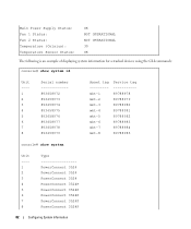
Main Power Supply Status: Fan 1 Status: Fan 2 Status: Temperature (Celsius): Temperature Sensor Status: OK NOT OPERATIONAL NOT OPERATIONAL 30 OK The following is an example of displaying ... Asset tag --------mkt-1 mkt-2 mkt-3 mkt-4 mkt-5 mkt-6 mkt-7 mkt-8 Service tag ----------89788978 89788979 89788980 89788981 89788982 89788983 89788984 89788985 console# show system Unit ---1 2 3 4 5 6 7 8 Type PowerConnect 3524 PowerConnect 3524 PowerConnect 3524 PowerConnect 3524P PowerConnect 3524P PowerConnect 3524P PowerConnect 3524P PowerConnect 3524P 82 Configuring System Information
Main Power Supply Status: Fan 1 Status: Fan 2 Status: Temperature (Celsius): Temperature Sensor Status: OK NOT OPERATIONAL NOT OPERATIONAL 30 OK The following is an example of displaying ... Asset tag --------mkt-1 mkt-2 mkt-3 mkt-4 mkt-5 mkt-6 mkt-7 mkt-8 Service tag ----------89788978 89788979 89788980 89788981 89788982 89788983 89788984 89788985 console# show system Unit ---1 2 3 4 5 6 7 8 Type PowerConnect 3524 PowerConnect 3524 PowerConnect 3524 PowerConnect 3524P PowerConnect 3524P PowerConnect 3524P PowerConnect 3524P PowerConnect 3524P 82 Configuring System Information
User's Guide
Page 92
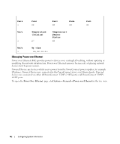
... are devices which receive power from the PowerConnect power supplies, for example IP phones. Powered Devices are connected via Ethernet ports. Power over Ethernet removes the necessity of placing network devices next to the PowerConnect device via either all PowerConnect 3524P's 24 FE ports or all PowerConnect 3548P's 48 FE ports. Powered Devices are connected to power sources. Fan1 1 Fan2 OK...
... are devices which receive power from the PowerConnect power supplies, for example IP phones. Powered Devices are connected via Ethernet ports. Power over Ethernet removes the necessity of placing network devices next to the PowerConnect device via either all PowerConnect 3524P's 24 FE ports or all PowerConnect 3548P's 48 FE ports. Powered Devices are connected to power sources. Fan1 1 Fan2 OK...
Getting Started Guide
Page 11
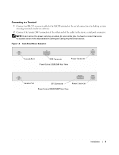
... Console Port RPS Connector Power Connector PowerConnect 3524/3548 Rear View Console Port EPS Connector Power Connector PowerConnect 3524P/3548P Rear View Installation 9 Connecting to a Terminal 1 Connect an RS-232 crossover cable to the ASCII terminal or the serial connector of the cable to ... at the other end of a desktop system running terminal emulation software. 2 Connect the female DB-9 connector at this time. Figure 1-3. NOTE: Do not connect the power cable to a power source in the steps detailed in Starting and Configuring the Device section.
... Console Port RPS Connector Power Connector PowerConnect 3524/3548 Rear View Console Port EPS Connector Power Connector PowerConnect 3524P/3548P Rear View Installation 9 Connecting to a Terminal 1 Connect an RS-232 crossover cable to the ASCII terminal or the serial connector of the cable to ... at the other end of a desktop system running terminal emulation software. 2 Connect the female DB-9 connector at this time. Figure 1-3. NOTE: Do not connect the power cable to a power source in the steps detailed in Starting and Configuring the Device section.


