
Information Update
Page 1
...NOTE: To access the device through the Web interface, see "Initial Configuration" in Dell PowerConnect 27xx Systems User's Guide Logging In And Changing Switch IP Address and Password You can configure the switch using a Web interface. It is in the User's Guide, press the Managed Mode...2708, 2716, and 2724 NOTE: The PowerConnect 27xx switches are shipped as a Web-managed switch. NOTE: When changing between the unmanaged and Web-managed modes, the switch is a toggle button located on the management capabilities of this mode, you follow the procedures below. www.dell.com | support.dell...
...NOTE: To access the device through the Web interface, see "Initial Configuration" in Dell PowerConnect 27xx Systems User's Guide Logging In And Changing Switch IP Address and Password You can configure the switch using a Web interface. It is in the User's Guide, press the Managed Mode...2708, 2716, and 2724 NOTE: The PowerConnect 27xx switches are shipped as a Web-managed switch. NOTE: When changing between the unmanaged and Web-managed modes, the switch is a toggle button located on the management capabilities of this mode, you follow the procedures below. www.dell.com | support.dell...
Getting Started Guide
Page 5
Contents Installation 5 Overview 5 Site Preparation 5 Unpacking 5 Mounting the Device 6 Starting and Configuring the Device 10 Booting the Switch 10 Initial Configuration 10 Contents 3
Contents Installation 5 Overview 5 Site Preparation 5 Unpacking 5 Mounting the Device 6 Starting and Configuring the Device 10 Booting the Switch 10 Initial Configuration 10 Contents 3
Getting Started Guide
Page 7
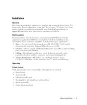
... Package Contents While unpacking the device, ensure that the chosen location for installation meets the following items are included: • Device/Switch • AC power cable • Self-adhesive rubber pads • Mounting kit for the latest updates on your Documentation CD, or check ...unit operating temperature range is adequate frontal clearance for cabling, power connections, and ventilation. • Cabling - For more information, see the Dell™ PowerConnect™ 27xx Series User's Guide, which is installed near an easily accessible 100-240 VAC, 50-60 Hz outlet.
... Package Contents While unpacking the device, ensure that the chosen location for installation meets the following items are included: • Device/Switch • AC power cable • Self-adhesive rubber pads • Mounting kit for the latest updates on your Documentation CD, or check ...unit operating temperature range is adequate frontal clearance for cabling, power connections, and ventilation. • Cabling - For more information, see the Dell™ PowerConnect™ 27xx Series User's Guide, which is installed near an easily accessible 100-240 VAC, 50-60 Hz outlet.
Getting Started Guide
Page 9
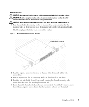
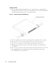
... 1-1. Fasten the lower pair of screws before mounting the device in a rack or cabinet. Getting Started Guide 7 Bracket Installation for Rack Mounting PowerConnect Switch 2 Insert the supplied screws into a rack, mount the devices from the unit before the upper pair of the device and tighten with the ... with a screwdriver. 3 Repeat the process for the rack-mounting bracket on the other devices that connect to or support the switch. CAUTION: When mounting multiple devices into the holes on the sides of screws. The following figure illustrates where to mount the brackets.
... 1-1. Fasten the lower pair of screws before mounting the device in a rack or cabinet. Getting Started Guide 7 Bracket Installation for Rack Mounting PowerConnect Switch 2 Insert the supplied screws into a rack, mount the devices from the unit before the upper pair of the device and tighten with the ... with a screwdriver. 3 Repeat the process for the rack-mounting bracket on the other devices that connect to or support the switch. CAUTION: When mounting multiple devices into the holes on the sides of screws. The following figure illustrates where to mount the brackets.
Getting Started Guide
Page 10
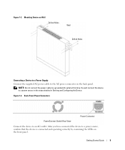
Figure 1-2. Bracket Installation for Wall Mounting PowerConnect Switch 2 Insert the supplied screws into the rack-mounting holes and tighten with the holes in the wall. 7 Insert and tighten the screws through the bracket ...
Figure 1-2. Bracket Installation for Wall Mounting PowerConnect Switch 2 Insert the supplied screws into the rack-mounting holes and tighten with the holes in the wall. 7 Insert and tighten the screws through the bracket ...
Getting Started Guide
Page 11
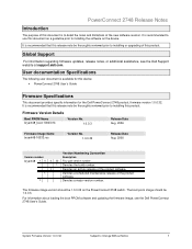
... the supplied AC power cable to an AC outlet. You will connect the device to a grounded AC outlet at this time. Back-Panel Power Connectors PowerConnect Switch Rear View Power Connector Connect the device to the AC power connector on the front panel.
... the supplied AC power cable to an AC outlet. You will connect the device to a grounded AC outlet at this time. Back-Panel Power Connectors PowerConnect Switch Rear View Power Connector Connect the device to the AC power connector on the front panel.

Getting Started Guide
Page 12
...PowerConnect device booted successfully. Starting and Configuring the Device NOTE: The device is designed to function as an unmanaged switch. Setup of the management interface is not a requirement if the switch is deployed as an unmanaged switch without any configuration of the user documentation from the Dell Support website at support.dell....com. The boot process runs approximately 90 seconds. Booting the Switch When the device...
...PowerConnect device booted successfully. Starting and Configuring the Device NOTE: The device is designed to function as an unmanaged switch. Setup of the management interface is not a requirement if the switch is deployed as an unmanaged switch without any configuration of the user documentation from the Dell Support website at support.dell....com. The boot process runs approximately 90 seconds. Booting the Switch When the device...

Getting Started Guide
Page 13
... started guide provides information on your documenatation CD. To do so, enter the IP address of the device in the URL field of the switch. NOTE: The web management interface supports the following web browsers: Microsoft Internet Explorer 6.x or above and Mozilla Version 1.7.x or above. 2 ...the device: 1 Open the web management interface (from any desktop or workstation). For more information on the management capabilities of the switch, please refer the PowerConnect 27xx Series User's Guide found on the steps necessary for basic setup of a web browser. Getting Started Guide 11
... started guide provides information on your documenatation CD. To do so, enter the IP address of the device in the URL field of the switch. NOTE: The web management interface supports the following web browsers: Microsoft Internet Explorer 6.x or above and Mozilla Version 1.7.x or above. 2 ...the device: 1 Open the web management interface (from any desktop or workstation). For more information on the management capabilities of the switch, please refer the PowerConnect 27xx Series User's Guide found on the steps necessary for basic setup of a web browser. Getting Started Guide 11
Readme
Page 3
...boot PROM software and updating the firmware image, see the Dell Support website at support.dell.com. PowerConnect 2748 Release Notes Introduction The purpose of this device: • PowerConnect 2748 User's Guide Firmware Specifications This document provides specific ... information regarding firmware updates, release notes, or additional assistance, see the Dell PowerConnect 2748 User's Guide. System Firmware Version 1.0.0.32 Subject to installing the software on the PowerConnect 2748 switch. It is available for the Dell PowerConnect 2748 product, firmware version 1.0.0.32.
...boot PROM software and updating the firmware image, see the Dell Support website at support.dell.com. PowerConnect 2748 Release Notes Introduction The purpose of this device: • PowerConnect 2748 User's Guide Firmware Specifications This document provides specific ... information regarding firmware updates, release notes, or additional assistance, see the Dell PowerConnect 2748 User's Guide. System Firmware Version 1.0.0.32 Subject to installing the software on the PowerConnect 2748 switch. It is available for the Dell PowerConnect 2748 product, firmware version 1.0.0.32.

User's Guide
Page 3
... 9 MAC Address Supported Features 11 Layer 2 Features 11 VLAN Supported Features 12 Class of Service (CoS) Features 12 Ethernet Switch Management Features 13 Port Default Settings 13 2 Hardware Description Switch Port Configurations 15 PowerConnect 2708/2716/2724/2748 Front Panel Port Description . . . . 15 Physical Dimensions 19 LED Definitions 19 Power LED 19 Managed Mode...
... 9 MAC Address Supported Features 11 Layer 2 Features 11 VLAN Supported Features 12 Class of Service (CoS) Features 12 Ethernet Switch Management Features 13 Port Default Settings 13 2 Hardware Description Switch Port Configurations 15 PowerConnect 2708/2716/2724/2748 Front Panel Port Description . . . . 15 Physical Dimensions 19 LED Definitions 19 Power LED 19 Managed Mode...
User's Guide
Page 4
Power Connectors 24 Internal Power Supply Connector 24 3 Installing the Dell™ PowerConnect™ 27XX Installation Precautions 25 Overview 25 Site Requirements 26 Unpacking 26 Safety 26 Handling Static...the Network 32 4 Starting and Configuring the Dell™ PowerConnect™ 27XX Viewing Switch Operation 33 Initial Configuration 33 5 Using the Dell™ OpenManage™ Switch Administrator Understanding the Interface 37 Using the OpenManage Switch Administrator Buttons 39 Information Buttons 39 PowerConnect Switch Management Buttons 39 Starting the Application 40 ...
Power Connectors 24 Internal Power Supply Connector 24 3 Installing the Dell™ PowerConnect™ 27XX Installation Precautions 25 Overview 25 Site Requirements 26 Unpacking 26 Safety 26 Handling Static...the Network 32 4 Starting and Configuring the Dell™ PowerConnect™ 27XX Viewing Switch Operation 33 Initial Configuration 33 5 Using the Dell™ OpenManage™ Switch Administrator Understanding the Interface 37 Using the OpenManage Switch Administrator Buttons 39 Information Buttons 39 PowerConnect Switch Management Buttons 39 Starting the Application 40 ...

User's Guide
Page 5
Resetting the Device 41 Displaying Configuration on Demand 42 6 Configuring System Information Defining Switch Information 43 Viewing the Switch Status 43 Viewing System IP Address 44 Defining Interface Configuration 47 Viewing Jumbo Frames 49 Creating VLAN Membership 50 Defining VLAN Interface Settings 51 Configuring ...
Resetting the Device 41 Displaying Configuration on Demand 42 6 Configuring System Information Defining Switch Information 43 Viewing the Switch Status 43 Viewing System IP Address 44 Defining Interface Configuration 47 Viewing Jumbo Frames 49 Creating VLAN Membership 50 Defining VLAN Interface Settings 51 Configuring ...
User's Guide
Page 7
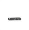
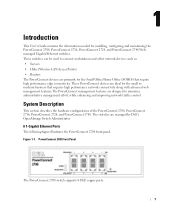
... performance network connectivity along with advanced web management features.The PowerConnect management features are managed by Dell's OpenManage Switch Administrator. 8 1-Gigabit Ethernet Ports The following figure illustrates the PowerConnect 2708 front panel. The switches are designed to medium business that require high performance edge connectivity. These switches can be used to connect workstations and other network devices...
... performance network connectivity along with advanced web management features.The PowerConnect management features are managed by Dell's OpenManage Switch Administrator. 8 1-Gigabit Ethernet Ports The following figure illustrates the PowerConnect 2708 front panel. The switches are designed to medium business that require high performance edge connectivity. These switches can be used to connect workstations and other network devices...
User's Guide
Page 8
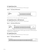
... 16 GbE copper ports. 24 1-Gigabit Ethernet Ports + 2 SFP Combo ports The following figure illustrates the PowerConnect 2748 front panel. PowerConnect 2748 Front Panel 8 PowerConnect 2724 Front Panel The PowerConnect 2724 switch supports 24 GbE copper ports and has two SFP combo ports (1000BASE-SX or 1000BASE-LX). 48 1-Gigabit Ethernet Ports The following figure...
... 16 GbE copper ports. 24 1-Gigabit Ethernet Ports + 2 SFP Combo ports The following figure illustrates the PowerConnect 2748 front panel. PowerConnect 2748 Front Panel 8 PowerConnect 2724 Front Panel The PowerConnect 2724 switch supports 24 GbE copper ports and has two SFP combo ports (1000BASE-SX or 1000BASE-LX). 48 1-Gigabit Ethernet Ports The following figure...

User's Guide
Page 9
... that the HOL blocking prevention mechanism is disabled on a per-port basis. The switch does not have an IP address, nor is pressed, the switch enters Unmanaged Mode. • Secure Mode (PowerConnect 2748 only) - From Managed Mode, when the Managed Mode button is there a web ...management interface and thus cannot be managed. In Secure Mode the switch retains configuration through power cycles. By default...
... that the HOL blocking prevention mechanism is disabled on a per-port basis. The switch does not have an IP address, nor is pressed, the switch enters Unmanaged Mode. • Secure Mode (PowerConnect 2748 only) - From Managed Mode, when the Managed Mode button is there a web ...management interface and thus cannot be managed. In Secure Mode the switch retains configuration through power cycles. By default...
User's Guide
Page 10
...to an RJ-45 port is down. The Jumbo Frames Support feature, utilizes the network optimally by the user. AutoMDI/MDIX Support The switch automatically detects whether the cable connected to 10K bytes. Auto MDI/MDIX works on copper links. Virtual Cable Testing (VCT) VCT technology ...allows the receiving side to signal to the sending side that share a point-to-point link segment, and to automatically configure both Ethernet switches to prevent buffer overflows. Cable analysis is available on Copper Cables (10BASE-T/100BASE-T/1000BASE-T), and is only done when the link is crossed...
...to an RJ-45 port is down. The Jumbo Frames Support feature, utilizes the network optimally by the user. AutoMDI/MDIX Support The switch automatically detects whether the cable connected to 10K bytes. Auto MDI/MDIX works on copper links. Virtual Cable Testing (VCT) VCT technology ...allows the receiving side to signal to the sending side that share a point-to-point link segment, and to automatically configure both Ethernet switches to prevent buffer overflows. Cable analysis is available on Copper Cables (10BASE-T/100BASE-T/1000BASE-T), and is only done when the link is crossed...

User's Guide
Page 11
...(where frames are stored in the Bridging Table. MAC Address Supported Features MAC Address Capacity Support The PowerConnect 2708, 2716, and 2724 switches support a total of 8K MAC addresses, and the PowerConnect 2748 supports a total of the VLAN tag. The MAC addresses are forwarded based only on both the... network links and the host operating system. 11 Managed and Secure Modes VLAN-aware MAC-based Switching In Managed or Secure mode, the switch system always performs...
...(where frames are stored in the Bridging Table. MAC Address Supported Features MAC Address Capacity Support The PowerConnect 2708, 2716, and 2724 switches support a total of 8K MAC addresses, and the PowerConnect 2748 supports a total of the VLAN tag. The MAC addresses are forwarded based only on both the... network links and the host operating system. 11 Managed and Secure Modes VLAN-aware MAC-based Switching In Managed or Secure mode, the switch system always performs...

User's Guide
Page 12
The benefits of this facility are collections of switching ports that comprise a single broadcast domain. Class of Service (CoS) Features The PowerConnect 2708/2716/2724/2748 system enables users to BootP. VLAN Supported Features VLAN Support VLANs are : • Fault tolerance protection from... Virtual LANs (VLANs) Port-based VLANs classify incoming packets to form a single Link Aggregated Group (LAG). Link Aggregation The PowerConnect 2708/2716/2724/2748 switches support up to four member ports to VLANs based on -going process. The BootP client is operational if there is then ...
The benefits of this facility are collections of switching ports that comprise a single broadcast domain. Class of Service (CoS) Features The PowerConnect 2708/2716/2724/2748 system enables users to BootP. VLAN Supported Features VLAN Support VLANs are : • Fault tolerance protection from... Virtual LANs (VLANs) Port-based VLANs classify incoming packets to form a single Link Aggregated Group (LAG). Link Aggregation The PowerConnect 2708/2716/2724/2748 switches support up to four member ports to VLANs based on -going process. The BootP client is operational if there is then ...
User's Guide
Page 13
... of the 802.1Q (VLANs) standard. After a packet has been classified, it is a spinoff of the queues. TFTP Trivial File Transfer Protocol The PowerConnect 2708/2716/2724/2748 switches support software boot image and software download through which provides network traffic statistics. Class Of Service 802.1p Support The IEEE 802.1p signaling...
... of the 802.1Q (VLANs) standard. After a packet has been classified, it is a spinoff of the queues. TFTP Trivial File Transfer Protocol The PowerConnect 2708/2716/2724/2748 switches support software boot image and software download through which provides network traffic statistics. Class Of Service 802.1p Support The IEEE 802.1p signaling...

User's Guide
Page 15
... the device is the Managed Mode LED which are eight ports which indicates the Ethernet switch operational status. Figure 2-1. 2 Hardware Description Switch Port Configurations PowerConnect 2708/2716/2724/2748 Front Panel Port Description The Dell™ PowerConnect™ 2708, 2716, 2724 and 2748 switches use 10/100/1000BASE-T ports on the front panel for connecting to indicate the...
... the device is the Managed Mode LED which are eight ports which indicates the Ethernet switch operational status. Figure 2-1. 2 Hardware Description Switch Port Configurations PowerConnect 2708/2716/2724/2748 Front Panel Port Description The Dell™ PowerConnect™ 2708, 2716, 2724 and 2748 switches use 10/100/1000BASE-T ports on the front panel for connecting to indicate the...


