
Information Update
Page 1
...2708, 2716, and 2724 NOTE: The PowerConnect 27xx switches are shipped as a Web-managed switch. NOTE: When changing between the unmanaged and Web-managed modes, the switch is configured with a default IP address (192.168.2.1) and a default user login (User Name: admin and no password). In this switch, follow the steps in Dell PowerConnect... of the management features of the switch, see "Initial Configuration" in Dell PowerConnect 27xx Systems User's Guide Logging In And Changing Switch IP Address and Password You can configure the switch using a Web interface. When changing to the...
...2708, 2716, and 2724 NOTE: The PowerConnect 27xx switches are shipped as a Web-managed switch. NOTE: When changing between the unmanaged and Web-managed modes, the switch is configured with a default IP address (192.168.2.1) and a default user login (User Name: admin and no password). In this switch, follow the steps in Dell PowerConnect... of the management features of the switch, see "Initial Configuration" in Dell PowerConnect 27xx Systems User's Guide Logging In And Changing Switch IP Address and Password You can configure the switch using a Web interface. When changing to the...
Information Update
Page 2
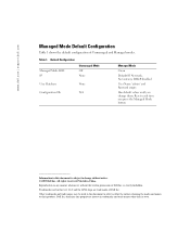
...this document is strictly forbidden. Resets each time you change without the written permission of Dell Inc. All rights reserved. Printed in this text: Dell and the DELL logo are trademarks of Unmanaged and Managed modes. Other trademarks and trade names may ... whatsoever without notice. © 2005 Dell Inc. Table 1. Reproduction in any proprietary interest in this document to refer to change them; Dell Inc. www.dell.com | support.dell.com Managed Mode Default Configuration Table 1 shows the default configuration of Dell Inc. is subject to either the ...
...this document is strictly forbidden. Resets each time you change without the written permission of Dell Inc. All rights reserved. Printed in this text: Dell and the DELL logo are trademarks of Unmanaged and Managed modes. Other trademarks and trade names may ... whatsoever without notice. © 2005 Dell Inc. Table 1. Reproduction in any proprietary interest in this document to refer to change them; Dell Inc. www.dell.com | support.dell.com Managed Mode Default Configuration Table 1 shows the default configuration of Dell Inc. is subject to either the ...
Getting Started Guide
Page 5
Contents Installation 5 Overview 5 Site Preparation 5 Unpacking 5 Mounting the Device 6 Starting and Configuring the Device 10 Booting the Switch 10 Initial Configuration 10 Contents 3
Contents Installation 5 Overview 5 Site Preparation 5 Unpacking 5 Mounting the Device 6 Starting and Configuring the Device 10 Booting the Switch 10 Initial Configuration 10 Contents 3
Getting Started Guide
Page 11
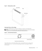
Back-Panel Power Connectors PowerConnect Switch Rear View Power Connector Connect the device to a power source in the steps detailed in Starting and Configuring the Device. You will connect the device to an AC outlet. Getting Started Guide 9 Figure 1-4. Figure 1-3. After you have connected the device to a grounded AC ...
Back-Panel Power Connectors PowerConnect Switch Rear View Power Connector Connect the device to a power source in the steps detailed in Starting and Configuring the Device. You will connect the device to an AC outlet. Getting Started Guide 9 Figure 1-4. Figure 1-3. After you have connected the device to a grounded AC ...

Getting Started Guide
Page 12
... unmanaged switch without any configuration of the user documentation from the Dell Support website at support.dell.com. NOTE: Before proceeding, read the release notes for configuring the default route. 10 Getting Started Guide NOTE: Obtain the following assumptions: • The PowerConnect device is being supplied to configure the device with the pre configured default IP (192...
... unmanaged switch without any configuration of the user documentation from the Dell Support website at support.dell.com. NOTE: Before proceeding, read the release notes for configuring the default route. 10 Getting Started Guide NOTE: Obtain the following assumptions: • The PowerConnect device is being supplied to configure the device with the pre configured default IP (192...

Getting Started Guide
Page 13
... the IP Address, Subnet Mask and Default Gateway. 4 Click Apply Changes. To configure the device: 1 Open the web management interface (from any desktop or workstation). For more information on the management capabilities of the switch, please refer the PowerConnect 27xx Series User's Guide found on the steps necessary for basic setup of...
... the IP Address, Subnet Mask and Default Gateway. 4 Click Apply Changes. To configure the device: 1 Open the web management interface (from any desktop or workstation). For more information on the management capabilities of the switch, please refer the PowerConnect 27xx Series User's Guide found on the steps necessary for basic setup of...

User's Guide
Page 3
... 2 Features 11 VLAN Supported Features 12 Class of Service (CoS) Features 12 Ethernet Switch Management Features 13 Port Default Settings 13 2 Hardware Description Switch Port Configurations 15 PowerConnect 2708/2716/2724/2748 Front Panel Port Description . . . . 15 Physical Dimensions 19 LED Definitions 19 Power LED 19 Managed Mode LED 19 Fan LED (2748...
... 2 Features 11 VLAN Supported Features 12 Class of Service (CoS) Features 12 Ethernet Switch Management Features 13 Port Default Settings 13 2 Hardware Description Switch Port Configurations 15 PowerConnect 2708/2716/2724/2748 Front Panel Port Description . . . . 15 Physical Dimensions 19 LED Definitions 19 Power LED 19 Managed Mode LED 19 Fan LED (2748...
User's Guide
Page 4
Power Connectors 24 Internal Power Supply Connector 24 3 Installing the Dell™ PowerConnect™ 27XX Installation Precautions 25 Overview 25 Site Requirements 26 Unpacking 26 Safety 26 Handling Static Sensitive Devices 27 Package... the Device to AC Power Supply 31 Connecting the Device to the Network 32 4 Starting and Configuring the Dell™ PowerConnect™ 27XX Viewing Switch Operation 33 Initial Configuration 33 5 Using the Dell™ OpenManage™ Switch Administrator Understanding the Interface 37 Using the OpenManage Switch Administrator Buttons 39 ...
Power Connectors 24 Internal Power Supply Connector 24 3 Installing the Dell™ PowerConnect™ 27XX Installation Precautions 25 Overview 25 Site Requirements 26 Unpacking 26 Safety 26 Handling Static Sensitive Devices 27 Package... the Device to AC Power Supply 31 Connecting the Device to the Network 32 4 Starting and Configuring the Dell™ PowerConnect™ 27XX Viewing Switch Operation 33 Initial Configuration 33 5 Using the Dell™ OpenManage™ Switch Administrator Understanding the Interface 37 Using the OpenManage Switch Administrator Buttons 39 ...

User's Guide
Page 5
...Information 43 Viewing the Switch Status 43 Viewing System IP Address 44 Defining Interface Configuration 47 Viewing Jumbo Frames 49 Creating VLAN Membership 50 Defining VLAN Interface Settings 51 Configuring LAG Membership 52 Managing System Files 54 Downloading Files From Server 55 Downloading ...Cables 61 Optical Transceivers Diagnostics 63 Port Mirroring 64 Enabling Storm Control 65 7 Configuring Quality of Service Quality of Service (QoS) Overview 69 CoS Services 70 Defining CoS Settings 71 Configuring QoS Settings 71 Mapping CoS Values to Queues 72 Mapping DSCP Values to ...
...Information 43 Viewing the Switch Status 43 Viewing System IP Address 44 Defining Interface Configuration 47 Viewing Jumbo Frames 49 Creating VLAN Membership 50 Defining VLAN Interface Settings 51 Configuring LAG Membership 52 Managing System Files 54 Downloading Files From Server 55 Downloading ...Cables 61 Optical Transceivers Diagnostics 63 Port Mirroring 64 Enabling Storm Control 65 7 Configuring Quality of Service Quality of Service (QoS) Overview 69 CoS Services 70 Defining CoS Settings 71 Configuring QoS Settings 71 Mapping CoS Values to Queues 72 Mapping DSCP Values to ...
User's Guide
Page 7
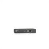
... Access Points) • Routers The PowerConnect devices are managed by Dell's OpenManage Switch Administrator. 8 1-Gigabit Ethernet Ports The following figure illustrates the PowerConnect 2708 front panel. The switches are primarily for...configurations of the PowerConnect 2708, PowerConnect 2716, PowerConnect 2724, and PowerConnect 2748. PowerConnect 2708 Front Panel The PowerConnect 2708 switch supports 8 GbE copper ports. 7 These PowerConnect devices are ideal for installing, configuring and maintaining the PowerConnect 2708, PowerConnect 2716, PowerConnect 2724, and PowerConnect...
... Access Points) • Routers The PowerConnect devices are managed by Dell's OpenManage Switch Administrator. 8 1-Gigabit Ethernet Ports The following figure illustrates the PowerConnect 2708 front panel. The switches are primarily for...configurations of the PowerConnect 2708, PowerConnect 2716, PowerConnect 2724, and PowerConnect 2748. PowerConnect 2708 Front Panel The PowerConnect 2708 switch supports 8 GbE copper ports. 7 These PowerConnect devices are ideal for installing, configuring and maintaining the PowerConnect 2708, PowerConnect 2716, PowerConnect 2724, and PowerConnect...

User's Guide
Page 9
...IP address of the queue are forwarded before packets at Half Duplex only. 9 Provides switch management through a web interface, and maintains the device configuration through power cycles just like Managed Mode. HOL blocking queues packets, and the packets at the head of 192.168.2.1. • Managed Mode... of the queue. The switch does not have an IP address, nor is pressed, the switch enters Unmanaged Mode. • Secure Mode (PowerConnect 2748 only) - This is unavailable for the same egress port resources. Once enabled, it is the system default. This is done by occupying...
...IP address of the queue are forwarded before packets at Half Duplex only. 9 Provides switch management through a web interface, and maintains the device configuration through power cycles just like Managed Mode. HOL blocking queues packets, and the packets at the head of 192.168.2.1. • Managed Mode... of the queue. The switch does not have an IP address, nor is pressed, the switch enters Unmanaged Mode. • Secure Mode (PowerConnect 2748 only) - This is unavailable for the same egress port resources. Once enabled, it is the system default. This is done by occupying...
User's Guide
Page 10
... (FDX), the flow control mechanism allows the receiving side to signal to the sending side that share a point-to-point link segment, and to automatically configure both Ethernet switches to configure the port speeds advertised. Port advertisement allows the system administrator to take maximum advantage of operation.
... (FDX), the flow control mechanism allows the receiving side to signal to the sending side that share a point-to-point link segment, and to automatically configure both Ethernet switches to configure the port speeds advertised. Port advertisement allows the system administrator to take maximum advantage of operation.

User's Guide
Page 11
.... MAC Address Supported Features MAC Address Capacity Support The PowerConnect 2708, 2716, and 2724 switches support a total of 8K MAC addresses, and the PowerConnect 2748 supports a total of Multicast and Broadcast frames accepted and forwarded by the switch. However, a similar functionality may be configured for MAC Addresses MAC addresses from which target port receives...
.... MAC Address Supported Features MAC Address Capacity Support The PowerConnect 2708, 2716, and 2724 switches support a total of 8K MAC addresses, and the PowerConnect 2748 supports a total of Multicast and Broadcast frames accepted and forwarded by the switch. However, a similar functionality may be configured for MAC Addresses MAC addresses from which target port receives...

User's Guide
Page 12
...server IP address and a download file name. Packets sharing common attributes can then configure these values to the TFTP client and try to VLANs based on their ingress port. Link Aggregation The PowerConnect 2708/2716/2724/2748 switches support up to four member ports to BootP. BootP ...and DHCP Clients DHCP (Dynamic Host Configuration Protocol) enables additional setup parameters to be received from physical link disruption ...
...server IP address and a download file name. Packets sharing common attributes can then configure these values to the TFTP client and try to VLANs based on their ingress port. Link Aggregation The PowerConnect 2708/2716/2724/2748 switches support up to four member ports to BootP. BootP ...and DHCP Clients DHCP (Dynamic Host Configuration Protocol) enables additional setup parameters to be received from physical link disruption ...
User's Guide
Page 13
...control objects, allowing real-time information to the Simple Network Management Protocol (SNMP), which the system can be monitored and configured. The PowerConnect 2708/2716/2724/2748 system can be captured across the entire network. The 802.1p is defined by the user, whereby ...packets are related to view the results, using the Web management interface in the system. TFTP Trivial File Transfer Protocol The PowerConnect 2708/2716/2724/2748 switches support software boot image and software download through which provides network traffic statistics. A CoS is a spinoff ...
...control objects, allowing real-time information to the Simple Network Management Protocol (SNMP), which the system can be monitored and configured. The PowerConnect 2708/2716/2724/2748 system can be captured across the entire network. The 802.1p is defined by the user, whereby ...packets are related to view the results, using the Web management interface in the system. TFTP Trivial File Transfer Protocol The PowerConnect 2708/2716/2724/2748 switches support software boot image and software download through which provides network traffic statistics. A CoS is a spinoff ...

User's Guide
Page 15
... panel is powered on the front panel, restores the device's default settings configuration. 15 Figure 2-1. On each port there are numbered 1 to 8, top down and left side of the PowerConnect 2708/2716/2724/2748 switches. These ports support autonegotiation, duplex mode (Half or... Mode LED which are LEDs (Light Emitting Diode) to a network. 2 Hardware Description Switch Port Configurations PowerConnect 2708/2716/2724/2748 Front Panel Port Description The Dell™ PowerConnect™ 2708, 2716, 2724 and 2748 switches use 10/100/1000BASE-T ports on the front panel for connecting...
... panel is powered on the front panel, restores the device's default settings configuration. 15 Figure 2-1. On each port there are numbered 1 to 8, top down and left side of the PowerConnect 2708/2716/2724/2748 switches. These ports support autonegotiation, duplex mode (Half or... Mode LED which are LEDs (Light Emitting Diode) to a network. 2 Hardware Description Switch Port Configurations PowerConnect 2708/2716/2724/2748 Front Panel Port Description The Dell™ PowerConnect™ 2708, 2716, 2724 and 2748 switches use 10/100/1000BASE-T ports on the front panel for connecting...

User's Guide
Page 16
PowerConnect 2708 Back Panel Figure 2-3. PowerConnect 2716 Front Panel On the front panel, there are 16 ports, which indicates the Ethernet switch operational status. On the left to right. A Managed Mode push-button, located on the right side on or not. On each port there are numbered 1 to indicate the port status. PowerConnect 2716 Back...
PowerConnect 2708 Back Panel Figure 2-3. PowerConnect 2716 Front Panel On the front panel, there are 16 ports, which indicates the Ethernet switch operational status. On the left to right. A Managed Mode push-button, located on the right side on or not. On each port there are numbered 1 to indicate the port status. PowerConnect 2716 Back...

User's Guide
Page 17
... left side of a combo port can switch from the RJ-45 to the SFP (or vice versa) without resetting the device. PowerConnect 2724 Back Panel 17 Figure 2-5. Figure 2-6. PowerConnect 2724 Front Panel On the front panel there are 24 ports which are determined by the physical connection used on the front... status. NOTE: Only one of the two physical connections of the front panel is powered on the front panel, restores the device's default settings configuration. On each port there are present, the SFP port will be the active port, whereas the RJ-45 port will be used at any one...
... left side of a combo port can switch from the RJ-45 to the SFP (or vice versa) without resetting the device. PowerConnect 2724 Back Panel 17 Figure 2-5. Figure 2-6. PowerConnect 2724 Front Panel On the front panel there are 24 ports which are determined by the physical connection used on the front... status. NOTE: Only one of the two physical connections of the front panel is powered on the front panel, restores the device's default settings configuration. On each port there are present, the SFP port will be the active port, whereas the RJ-45 port will be used at any one...

User's Guide
Page 21
... Off No link is rebooted. 21 From Unmanaged or Secure Mode (2748 only), pressing the Managed Mode button causes: • Factory default configuration (192.168.2.1) is set as the switch IP address. • Subnet mask changes to 255.255.255.0 • Graphical User Interface (...to Managed Mode, the switch restores the configuration values to Admin, and the password is not configured (appears blank), with Read/Write privilege. • The DHCP client is set off. • The device is established. Table 2-5. Managed Mode Button The PowerConnect 2708/2716/2724/2748 has a Managed Mode...
... Off No link is rebooted. 21 From Unmanaged or Secure Mode (2748 only), pressing the Managed Mode button causes: • Factory default configuration (192.168.2.1) is set as the switch IP address. • Subnet mask changes to 255.255.255.0 • Graphical User Interface (...to Managed Mode, the switch restores the configuration values to Admin, and the password is not configured (appears blank), with Read/Write privilege. • The DHCP client is set off. • The device is established. Table 2-5. Managed Mode Button The PowerConnect 2708/2716/2724/2748 has a Managed Mode...
User's Guide
Page 25
... shock. 3 Installing the Dell™ PowerConnect™ 27XX This chapter contains information about unpacking, installation procedures, and how to change the switch 25 The process of installing the PowerConnect switch consists of physically installing these devices and configuring them. If the user ...wishes to radiators or heat sources. • Do not push foreign objects into the device's hardware enclosure, as a managed switch, they can simply plug the switch in the Product Information Guide. Overview The PowerConnect 2708/...
... shock. 3 Installing the Dell™ PowerConnect™ 27XX This chapter contains information about unpacking, installation procedures, and how to change the switch 25 The process of installing the PowerConnect switch consists of physically installing these devices and configuring them. If the user ...wishes to radiators or heat sources. • Do not push foreign objects into the device's hardware enclosure, as a managed switch, they can simply plug the switch in the Product Information Guide. Overview The PowerConnect 2708/...


