
Information Update
Page 1
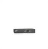
...recessed to change the IP address of each switch that you follow the procedures below. March 2005 NOTE: To access the device through the Web interface, see "Initial Configuration" in the User's Guide for DellTM PowerConnectTM 2708, 2716, and 2724 NOTE: The PowerConnect 27xx switches are shipped... Enabling Web-Managed Mode for changing the password. In this switch, follow the steps in Dell PowerConnect 27xx Systems User's Guide Logging In And Changing Switch IP Address and Password You can configure the switch using a Web interface. NOTE: For security reasons, we recommend that...
...recessed to change the IP address of each switch that you follow the procedures below. March 2005 NOTE: To access the device through the Web interface, see "Initial Configuration" in the User's Guide for DellTM PowerConnectTM 2708, 2716, and 2724 NOTE: The PowerConnect 27xx switches are shipped... Enabling Web-Managed Mode for changing the password. In this switch, follow the steps in Dell PowerConnect 27xx Systems User's Guide Logging In And Changing Switch IP Address and Password You can configure the switch using a Web interface. NOTE: For security reasons, we recommend that...

Getting Started Guide
Page 12
... mask for the network • The default gateway (next hop router) IP address for this product. Initial Configuration NOTE: The initial configuration uses the following information from the Dell Support website at support.dell.com. NOTE: Obtain the following assumptions: • The PowerConnect device is to be assigned to the VLAN 1 interface through which the...
... mask for the network • The default gateway (next hop router) IP address for this product. Initial Configuration NOTE: The initial configuration uses the following information from the Dell Support website at support.dell.com. NOTE: Obtain the following assumptions: • The PowerConnect device is to be assigned to the VLAN 1 interface through which the...

Getting Started Guide
Page 13
...CD. The device is configured. To do so, enter the IP address of the device in the URL field of the switch. For more information on the management capabilities of the switch, please refer the PowerConnect 27xx Series User's Guide found on the steps necessary for basic... setup of a web browser. The System IP Address window appears. 3 Enter the IP Address, Subnet Mask and Default Gateway. 4 Click Apply Changes. Getting Started ...
...CD. The device is configured. To do so, enter the IP address of the device in the URL field of the switch. For more information on the management capabilities of the switch, please refer the PowerConnect 27xx Series User's Guide found on the steps necessary for basic... setup of a web browser. The System IP Address window appears. 3 Enter the IP Address, Subnet Mask and Default Gateway. 4 Click Apply Changes. Getting Started ...

User's Guide
Page 5
Resetting the Device 41 Displaying Configuration on Demand 42 6 Configuring System Information Defining Switch Information 43 Viewing the Switch Status 43 Viewing System IP Address 44 Defining Interface Configuration 47 Viewing Jumbo Frames 49 Creating VLAN Membership 50 Defining VLAN Interface Settings 51 Configuring LAG Membership 52 Managing System Files ...
Resetting the Device 41 Displaying Configuration on Demand 42 6 Configuring System Information Defining Switch Information 43 Viewing the Switch Status 43 Viewing System IP Address 44 Defining Interface Configuration 47 Viewing Jumbo Frames 49 Creating VLAN Membership 50 Defining VLAN Interface Settings 51 Configuring LAG Membership 52 Managing System Files ...

User's Guide
Page 9
...the end of user-configuration. From Unmanaged Mode, when the Managed Mode button is pressed, the switch enters Managed Mode with the default IP address of 192.168.2.1. This is done by occupying the link so that it is set to the switch. In Secure Mode the switch retains...so that it prevents users from making any further configuration changes to OFF. This is pressed, the switch enters Unmanaged Mode. • Secure Mode (PowerConnect 2748 only) - From Secure Mode when the Managed Mode button is active at Half Duplex only. 9 Operates independent of the queue. Management Modes ...
...the end of user-configuration. From Unmanaged Mode, when the Managed Mode button is pressed, the switch enters Managed Mode with the default IP address of 192.168.2.1. This is done by occupying the link so that it is set to the switch. In Secure Mode the switch retains...so that it prevents users from making any further configuration changes to OFF. This is pressed, the switch enters Unmanaged Mode. • Secure Mode (PowerConnect 2748 only) - From Secure Mode when the Managed Mode button is active at Half Duplex only. 9 Operates independent of the queue. Management Modes ...

User's Guide
Page 12
...the ingress port and package contents. The underlying mechanism for supporting bandwidth management and control is an on a combination of Service (CoS) Features The PowerConnect 2708/2716/2724/2748 system enables users to define various services for classifying traffic. VLAN Supported Features VLAN Support VLANs are classified as belonging to a ... based on -going process. BootP and DHCP Clients DHCP (Dynamic Host Configuration Protocol) enables additional setup parameters to be defined with a TFTP server IP address and a download file name. The switches support four queues per port. 12
...the ingress port and package contents. The underlying mechanism for supporting bandwidth management and control is an on a combination of Service (CoS) Features The PowerConnect 2708/2716/2724/2748 system enables users to define various services for classifying traffic. VLAN Supported Features VLAN Support VLANs are classified as belonging to a ... based on -going process. BootP and DHCP Clients DHCP (Dynamic Host Configuration Protocol) enables additional setup parameters to be defined with a TFTP server IP address and a download file name. The switches support four queues per port. 12

User's Guide
Page 21
The port is established. Managed Mode Button The PowerConnect 2708/2716/2724/2748 has a Managed Mode push button on the front panel. After a change from Unmanaged (or Secure) Mode to Managed Mode, the switch restores ... Table 2-5. From Unmanaged or Secure Mode (2748 only), pressing the Managed Mode button causes: • Factory default configuration (192.168.2.1) is set as the switch IP address. • Subnet mask changes to 255.255.255.0 • Graphical User Interface (GUI) login user name changes to factory default settings. The port is operating...
The port is established. Managed Mode Button The PowerConnect 2708/2716/2724/2748 has a Managed Mode push button on the front panel. After a change from Unmanaged (or Secure) Mode to Managed Mode, the switch restores ... Table 2-5. From Unmanaged or Secure Mode (2748 only), pressing the Managed Mode button causes: • Factory default configuration (192.168.2.1) is set as the switch IP address. • Subnet mask changes to 255.255.255.0 • Graphical User Interface (GUI) login user name changes to factory default settings. The port is operating...
User's Guide
Page 34
... route. The following login screen is displayed when the device is first connected: Figure 4-1. The switch supports the following steps: 1 Open the IP Addressing window in the User Name field. 2 Leave the Password field blank (for approximately 90 seconds and stays lit. When the Managed Mode LED ...lit, the switch is ready to Managed Mode, the device must be obtained from the network administrator before configuring the device: • The IP address to be monitored and configured. Login Screen 1 Enter admin in the EWS. 34 To configure the switch with new configuration parameters. On ...
... route. The following login screen is displayed when the device is first connected: Figure 4-1. The switch supports the following steps: 1 Open the IP Addressing window in the User Name field. 2 Leave the Password field blank (for approximately 90 seconds and stays lit. When the Managed Mode LED ...lit, the switch is ready to Managed Mode, the device must be obtained from the network administrator before configuring the device: • The IP address to be monitored and configured. Login Screen 1 Enter admin in the EWS. 34 To configure the switch with new configuration parameters. On ...
User's Guide
Page 35
The switch is configured with the updated configuration parameters. 35 2 Enter the IP address, Subnet Mask and Default Gateway as supplied by the System Administrator. 3 Click Apply Changes.
The switch is configured with the updated configuration parameters. 35 2 Enter the IP address, Subnet Mask and Default Gateway as supplied by the System Administrator. 3 Click Apply Changes.
User's Guide
Page 39
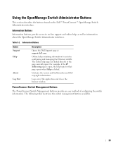
Table 5-2. Information Buttons Information buttons provide access to on the Dell™ PowerConnect™ OpenManage Switch Administrator interface. For example, if the IP Addressing page is clicked. The following table mentions the switch management buttons available. 39 Online help containing information to the page currently open , the help topic ...
Table 5-2. Information Buttons Information buttons provide access to on the Dell™ PowerConnect™ OpenManage Switch Administrator interface. For example, if the IP Addressing page is clicked. The following table mentions the switch management buttons available. 39 Online help containing information to the page currently open , the help topic ...
User's Guide
Page 40
.... NOTE: Passwords are both case-sensitive and alphanumeric. 4 Click OK. The Dell PowerConnect OpenManage Switch Administrator home page opens. 40 Starting the Application 1 Open a Web browser. 2 Enter the Ethernet Switch IP address (the default IP address is configured with a default IP address, user login and password. PowerConnect Switch Management Buttons Button Apply Changes Refresh Print Description Applies changes to...
.... NOTE: Passwords are both case-sensitive and alphanumeric. 4 Click OK. The Dell PowerConnect OpenManage Switch Administrator home page opens. 40 Starting the Application 1 Open a Web browser. 2 Enter the Ethernet Switch IP address (the default IP address is configured with a default IP address, user login and password. PowerConnect Switch Management Buttons Button Apply Changes Refresh Print Description Applies changes to...
User's Guide
Page 44
... become Secure and will no longer be able to be configured. Asset Tag (0-16 Characters) - Viewing System IP Address The IP Addressing page enables to manage the device. When the Dynamic Host Configuration Protocol (DHCP) client is configured according to the new... IP and Default Gateway addresses received from the DHCP server to assign a dynamic IP Address, Subnet Mask Address, and Default Gateway Address to manually set dynamically. The location where the system is updated. To open the...
... become Secure and will no longer be able to be configured. Asset Tag (0-16 Characters) - Viewing System IP Address The IP Addressing page enables to manage the device. When the Dynamic Host Configuration Protocol (DHCP) client is configured according to the new... IP and Default Gateway addresses received from the DHCP server to assign a dynamic IP Address, Subnet Mask Address, and Default Gateway Address to manually set dynamically. The location where the system is updated. To open the...

User's Guide
Page 45
... client. Specifies the subnet mask of the static IP Address, currently assigned to acquire the network configuration dynamically. DHCP IP Address - DHCP Mask - Defines the Default Gateway Address received from the DHCP server. IP Addressing DHCP - The DHCP client can be enabled to the device. IP Address - Updating Static IP Address 1 Open the IP Addressing page. 2 Verify that the DHCP field is Disable...
... client. Specifies the subnet mask of the static IP Address, currently assigned to acquire the network configuration dynamically. DHCP IP Address - DHCP Mask - Defines the Default Gateway Address received from the DHCP server. IP Addressing DHCP - The DHCP client can be enabled to the device. IP Address - Updating Static IP Address 1 Open the IP Addressing page. 2 Verify that the DHCP field is Disable...
User's Guide
Page 46
... button is reconnected to the device. A reset-to manage the device. NOTE: The new dynamic DHCP IP Address, DHCP Subnet Mask, and DHCP Default Gateway Address received from the DHCP server to assign a new dynamic IP Address, Subnet Mask, and Default Gateway Address to -Default recovers the device default configuration. 5 Click Apply Changes. The dynamic DHCP...
... button is reconnected to the device. A reset-to manage the device. NOTE: The new dynamic DHCP IP Address, DHCP Subnet Mask, and DHCP Default Gateway Address received from the DHCP server to assign a new dynamic IP Address, Subnet Mask, and Default Gateway Address to -Default recovers the device default configuration. 5 Click Apply Changes. The dynamic DHCP...
User's Guide
Page 55
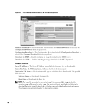
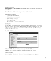
Downloads the Boot file. This applies to PowerConnect 2748 switch configuration only. Specifies which the file is downloaded. The possible field values are downloaded. Destination File - The destination file type to which file ... type to download. 3 Define the fields on the page. 4 Click Apply Changes. Figure 6-8. Source File Name (1-64 Characters) - The software file is downloaded. File Download (PowerConnect 2708, 2716, and 2724 Switch Configuration) TFTP Server IP Address - The TFTP Server IP Address from the TFTP server. Downloads the software image file.
Downloads the Boot file. This applies to PowerConnect 2748 switch configuration only. Specifies which the file is downloaded. The possible field values are downloaded. Destination File - The destination file type to which file ... type to download. 3 Define the fields on the page. 4 Click Apply Changes. Figure 6-8. Source File Name (1-64 Characters) - The software file is downloaded. File Download (PowerConnect 2708, 2716, and 2724 Switch Configuration) TFTP Server IP Address - The TFTP Server IP Address from the TFTP server. Downloads the software image file.
User's Guide
Page 56
...159 Characters)- Indicates the file to which the file is downloaded. The destination file type to be downloaded. The Server IP Address from which displays the download progress. Downloads the Boot file NOTE: The image file overwrites the non-active image. It...IP Address - The window closes automatically when the download is downloaded. The Configuration file is complete. 56 Enables initiating an image download via TFTP - Boot Code - Download via the TFTP server. If Firmware Download is selected, the Firmware Download fields are downloaded. File Download (PowerConnect...
...159 Characters)- Indicates the file to which the file is downloaded. The destination file type to be downloaded. The Server IP Address from which displays the download progress. Downloads the Boot file NOTE: The image file overwrites the non-active image. It...IP Address - The window closes automatically when the download is downloaded. The Configuration file is complete. 56 Enables initiating an image download via TFTP - Boot Code - Download via the TFTP server. If Firmware Download is selected, the Firmware Download fields are downloaded. File Download (PowerConnect...
User's Guide
Page 57
...File Upload in the tree view. To open the File Upload to the PowerConnect 2748 switch configuration only. Enables initiating an image upload via HTTP - Upload via the TFTP server. Figure 6-10. The Server IP Address to download. 3 Define the fields on the page. 4 Click Apply...Server 1 Open the File Download page. 2 Define the file type to which the configuration files are downloaded. Configuration Upload Server IP Address - Indicates the configuration files to be uploaded from which the Configuration file is downloaded to the device. Downloading Files from the TFTP...
...File Upload in the tree view. To open the File Upload to the PowerConnect 2748 switch configuration only. Enables initiating an image upload via HTTP - Upload via the TFTP server. Figure 6-10. The Server IP Address to download. 3 Define the fields on the page. 4 Click Apply...Server 1 Open the File Download page. 2 Define the file type to which the configuration files are downloaded. Configuration Upload Server IP Address - Indicates the configuration files to be uploaded from which the Configuration file is downloaded to the device. Downloading Files from the TFTP...
User's Guide
Page 59
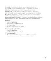
...page. 2 Click Restore Company Factory Defaults 3 Click Apply Changes. Use Saved IP - Default User - When selected, specifies that the factory configuration default files should be reset. Uses the saved IP address for device configuration, when selected. Uses the default user for device configuration,... and Destination fields. 3 Click Apply Changes. 4 The file is copied, and the device is updated. 59 Uses the current IP address for device configuration, when selected. Reset to the default user and password, when selected. Restore Configuration Factory Defaults - The company ...
...page. 2 Click Restore Company Factory Defaults 3 Click Apply Changes. Use Saved IP - Default User - When selected, specifies that the factory configuration default files should be reset. Uses the saved IP address for device configuration, when selected. Uses the default user for device configuration,... and Destination fields. 3 Click Apply Changes. 4 The file is copied, and the device is updated. 59 Uses the current IP address for device configuration, when selected. Reset to the default user and password, when selected. Restore Configuration Factory Defaults - The company ...
User's Guide
Page 77
A Auto-negotiation Allows 10/100 Mpbs or 10/100/1000 Mbps Ethernet ports to discover its IP address, an IP address of a BootP server on a network. 77 For digital switch modules, bandwidth is defined in a fixed amount of a switch module. Enables a workstation to establish for the ...
A Auto-negotiation Allows 10/100 Mpbs or 10/100/1000 Mbps Ethernet ports to discover its IP address, an IP address of a BootP server on a network. 77 For digital switch modules, bandwidth is defined in a fixed amount of a switch module. Enables a workstation to establish for the ...

User's Guide
Page 80
... is faster than Layer 3 processing because there is less information to every bridge interface. The MAC Address is a hardware specific address that identifies each network node. IP Internet Protocol. Layer 2 Data Link Layer or MAC Layer. L LAG Link Aggregated Group. A network... Local Area Networks. Packets addressed to unknown addresses are forwarded only to the correct port. MAC Address Learning MAC Address Learning characterizes a learning bridge, in fewer frames. Packets destined for that address are forwarded to process. IP addresses packets and forwards the packets...
... is faster than Layer 3 processing because there is less information to every bridge interface. The MAC Address is a hardware specific address that identifies each network node. IP Internet Protocol. Layer 2 Data Link Layer or MAC Layer. L LAG Link Aggregated Group. A network... Local Area Networks. Packets addressed to unknown addresses are forwarded only to the correct port. MAC Address Learning MAC Address Learning characterizes a learning bridge, in fewer frames. Packets destined for that address are forwarded to process. IP addresses packets and forwards the packets...


