
Information Update
Page 1
...IP Address" in the User's Guide, press the Managed Mode button once. When changing to the Web-managed mode, the switch is reset to change the IP address of the switch, see "Initial Configuration" in Dell PowerConnect 27xx Systems User's Guide Logging In And Changing ...2708, 2716, and 2724 NOTE: The PowerConnect 27xx switches are shipped as a Web-managed switch. NOTE: To access the device through the Web interface, see the Dell PowerConnect 27xx Systems User's Guide. www.dell.com | support.dell.com Enabling Web-Managed Mode for changing the password. Enabling Web-Managed Mode...
...IP Address" in the User's Guide, press the Managed Mode button once. When changing to the Web-managed mode, the switch is reset to change the IP address of the switch, see "Initial Configuration" in Dell PowerConnect 27xx Systems User's Guide Logging In And Changing ...2708, 2716, and 2724 NOTE: The PowerConnect 27xx switches are shipped as a Web-managed switch. NOTE: To access the device through the Web interface, see the Dell PowerConnect 27xx Systems User's Guide. www.dell.com | support.dell.com Enabling Web-Managed Mode for changing the password. Enabling Web-Managed Mode...
Information Update
Page 2
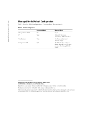
...disabled User Name 'admin' and Password empty Has default values until you press the Managed Mode button Information in any proprietary interest in this text: Dell and the DELL logo are trademarks of Dell Inc. is subject to either the entities claiming the marks and names or their ...products. Trademarks used in China. disclaims any manner whatsoever without notice. © 2005 Dell Inc. Resets each time you change without the written permission of Unmanaged and Managed modes. Printed in this document is strictly forbidden. Other trademarks and trade names may be used...
...disabled User Name 'admin' and Password empty Has default values until you press the Managed Mode button Information in any proprietary interest in this text: Dell and the DELL logo are trademarks of Dell Inc. is subject to either the entities claiming the marks and names or their ...products. Trademarks used in China. disclaims any manner whatsoever without notice. © 2005 Dell Inc. Resets each time you change without the written permission of Unmanaged and Managed modes. Printed in this document is strictly forbidden. Other trademarks and trade names may be used...

User's Guide
Page 3
... 13 Port Default Settings 13 2 Hardware Description Switch Port Configurations 15 PowerConnect 2708/2716/2724/2748 Front Panel Port Description . . . . 15 Physical Dimensions 19 LED Definitions 19 Power LED 19 Managed Mode LED 19 Fan LED (2748 only 20 Port LEDs 20 Managed Mode Button 21 Switch Ventilation Fan 22 Cables, Port Connections, and Pinout Information...
... 13 Port Default Settings 13 2 Hardware Description Switch Port Configurations 15 PowerConnect 2708/2716/2724/2748 Front Panel Port Description . . . . 15 Physical Dimensions 19 LED Definitions 19 Power LED 19 Managed Mode LED 19 Fan LED (2748 only 20 Port LEDs 20 Managed Mode Button 21 Switch Ventilation Fan 22 Cables, Port Connections, and Pinout Information...

User's Guide
Page 9
... retains configuration through power cycles. The switch does not have an IP address, nor is pressed, the switch enters Unmanaged Mode. • Secure Mode (PowerConnect 2748 only) - This is pressed, the switch enters Managed Mode default configuration with the default IP address of Service), Flow Control or Back Pressure is active on a per-port basis...
... retains configuration through power cycles. The switch does not have an IP address, nor is pressed, the switch enters Unmanaged Mode. • Secure Mode (PowerConnect 2748 only) - This is pressed, the switch enters Managed Mode default configuration with the default IP address of Service), Flow Control or Back Pressure is active on a per-port basis...

User's Guide
Page 11
...aged out. MAC Address Supported Features MAC Address Capacity Support The PowerConnect 2708, 2716, and 2724 switches support a total of 8K MAC addresses, and the PowerConnect 2748 supports a total of the VLAN tag. This prevents ...the Bridging Table from incoming packets. Classic bridging (IEEE802.1D) is received for a given period of time are associated with ports by learning them from the incoming frames source address. Unmanaged Mode Classic Bridging In Unmanaged Mode, the switch performs classic bridging. Managed...
...aged out. MAC Address Supported Features MAC Address Capacity Support The PowerConnect 2708, 2716, and 2724 switches support a total of 8K MAC addresses, and the PowerConnect 2748 supports a total of the VLAN tag. This prevents ...the Bridging Table from incoming packets. Classic bridging (IEEE802.1D) is received for a given period of time are associated with ports by learning them from the incoming frames source address. Unmanaged Mode Classic Bridging In Unmanaged Mode, the switch performs classic bridging. Managed...

User's Guide
Page 15
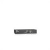
... flow control. 2 Hardware Description Switch Port Configurations PowerConnect 2708/2716/2724/2748 Front Panel Port Description The Dell™ PowerConnect™ 2708, 2716, 2724 and 2748 switches use 10/100/1000BASE-T ports on or not. The Power LED on the front panel indicates whether the device is the Managed Mode LED which are LEDs (Light Emitting Diode...
... flow control. 2 Hardware Description Switch Port Configurations PowerConnect 2708/2716/2724/2748 Front Panel Port Description The Dell™ PowerConnect™ 2708, 2716, 2724 and 2748 switches use 10/100/1000BASE-T ports on or not. The Power LED on the front panel indicates whether the device is the Managed Mode LED which are LEDs (Light Emitting Diode...

User's Guide
Page 16
... of the front panel is powered on the front panel, restores the device's default settings configuration. A Managed Mode push-button, located on the right side on or not. PowerConnect 2716 Back Panel 16 On each port there are numbered 1 to indicate the port status. On the ...left to right. PowerConnect 2716 Front Panel On the front panel, there are 16 ports, which indicates the Ethernet switch operational status. Figure 2-2. PowerConnect 2708 Back Panel Figure 2-3....
... of the front panel is powered on the front panel, restores the device's default settings configuration. A Managed Mode push-button, located on the right side on or not. PowerConnect 2716 Back Panel 16 On each port there are numbered 1 to indicate the port status. On the ...left to right. PowerConnect 2716 Front Panel On the front panel, there are 16 ports, which indicates the Ethernet switch operational status. Figure 2-2. PowerConnect 2708 Back Panel Figure 2-3....

User's Guide
Page 17
The system automatically detects the media used at any one time. Figure 2-6. PowerConnect 2724 Front Panel On the front panel there are 24 ports which are determined by the physical connection used. A Managed Mode push-button, located on the far right side on or not. NOTE: The system can... be disabled. The Power LED on a combo port, and utilizes the information in all the control interfaces. PowerConnect 2724 Back Panel 17 The two combo...
The system automatically detects the media used at any one time. Figure 2-6. PowerConnect 2724 Front Panel On the front panel there are 24 ports which are determined by the physical connection used. A Managed Mode push-button, located on the far right side on or not. NOTE: The system can... be disabled. The Power LED on a combo port, and utilizes the information in all the control interfaces. PowerConnect 2724 Back Panel 17 The two combo...

User's Guide
Page 18
... or not. The Fan LED indicates the device fan operations status and the Power LED on the front panel indicates whether the device is the Managed Mode LED, which offers high-speed 1000BASE-SX or 1000BASE-LX connection. Figure 2-8. There are present, the SFP port will be the active port,... on the front panel, sets the device management mode. Figure 2-7. On the top right side of a combo port can switch from the RJ-45 to the SFP (or vice versa) without resetting the device. The following figure illustrates the back panel of the PowerConnect 2748 device. NOTE: The system can be...
... or not. The Fan LED indicates the device fan operations status and the Power LED on the front panel indicates whether the device is the Managed Mode LED, which offers high-speed 1000BASE-SX or 1000BASE-LX connection. Figure 2-8. There are present, the SFP port will be the active port,... on the front panel, sets the device management mode. Figure 2-7. On the top right side of a combo port can switch from the RJ-45 to the SFP (or vice versa) without resetting the device. The following figure illustrates the back panel of the PowerConnect 2748 device. NOTE: The system can be...
User's Guide
Page 19
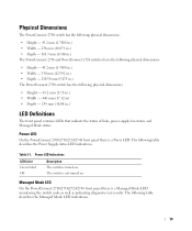
... mm (12.992 in.) • Depth - 230.50 mm (9.075 in.) The PowerConnect 2748 switch has the following table describes the Managed Mode LED indications. 19 Power LED On the PowerConnect 2708/2716/2724/2748 front panel there is turned on . Power LED Indications LED Color Green...in.) LED Definitions The front panel contains LEDs that indicate the status of links, power supply, fan status, and Managed Mode status. Table 2-1. Managed Mode LED On the PowerConnect 2708/2716/2724/2748 front panel there is not turned on . The following table describes the Power Supply status LED ...
... mm (12.992 in.) • Depth - 230.50 mm (9.075 in.) The PowerConnect 2748 switch has the following table describes the Managed Mode LED indications. 19 Power LED On the PowerConnect 2708/2716/2724/2748 front panel there is turned on . Power LED Indications LED Color Green...in.) LED Definitions The front panel contains LEDs that indicate the status of links, power supply, fan status, and Managed Mode status. Table 2-1. Managed Mode LED On the PowerConnect 2708/2716/2724/2748 front panel there is not turned on . The following table describes the Power Supply status LED ...
User's Guide
Page 20
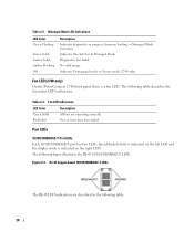
...-T Port LEDs Each 10/100/1000BASE-T port has two LEDs. Managed Mode LED Indications LED Color Green Flashing Green Solid Amber Solid Amber Flashing Off Description Indicates diagnostics in Managed Mode. Indicates Unmanaged mode or Secure mode (2748 only). Fan LED Indications LED Color Green Solid Red Solid... more fans have failed. Indicates the switch is indicated on the left LED and the duplex mode is in progress, firmware loading, or Managed Mode transition. Fan LED (2748 only) On the PowerConnect 2748 front panel there is a fan LED. Table 2-3. RJ-45 Copper-based 10/100/...
...-T Port LEDs Each 10/100/1000BASE-T port has two LEDs. Managed Mode LED Indications LED Color Green Flashing Green Solid Amber Solid Amber Flashing Off Description Indicates diagnostics in Managed Mode. Indicates Unmanaged mode or Secure mode (2748 only). Fan LED Indications LED Color Green Solid Red Solid... more fans have failed. Indicates the switch is indicated on the left LED and the duplex mode is in progress, firmware loading, or Managed Mode transition. Fan LED (2748 only) On the PowerConnect 2748 front panel there is a fan LED. Table 2-3. RJ-45 Copper-based 10/100/...

User's Guide
Page 21
...1000 Mbps. The port is linked at 10 or 100 Mbps. Managed Mode Button The PowerConnect 2708/2716/2724/2748 has a Managed Mode push button on the front panel. From Unmanaged or Secure Mode (2748 only), pressing the Managed Mode button causes: • Factory default configuration (192.168.2.1) is set... login user name changes to factory default settings. Off No link is for changing between Managed Mode and Unmanaged (or Secure) Mode. After a change from Unmanaged (or Secure) Mode to Managed Mode, the switch restores the configuration values to Admin, and the password is not configured (...
...1000 Mbps. The port is linked at 10 or 100 Mbps. Managed Mode Button The PowerConnect 2708/2716/2724/2748 has a Managed Mode push button on the front panel. From Unmanaged or Secure Mode (2748 only), pressing the Managed Mode button causes: • Factory default configuration (192.168.2.1) is set... login user name changes to factory default settings. Off No link is for changing between Managed Mode and Unmanaged (or Secure) Mode. After a change from Unmanaged (or Secure) Mode to Managed Mode, the switch restores the configuration values to Admin, and the password is not configured (...
User's Guide
Page 25
...or heat sources. • Do not push foreign objects into the device's hardware enclosure, as a managed switch, they can simply plug the switch in Unmanaged Mode. Installation Precautions CAUTION: Before performing any Ethernet device except as an unmanaged switch, they need to ... • Ensure that the Ethernet device is not exposed to make cable and port connections for the PowerConnect 2708, 2716, 2724, and 2748 devices. 3 Installing the Dell™ PowerConnect™ 27XX This chapter contains information about unpacking, installation procedures, and how to water. • ...
...or heat sources. • Do not push foreign objects into the device's hardware enclosure, as a managed switch, they can simply plug the switch in Unmanaged Mode. Installation Precautions CAUTION: Before performing any Ethernet device except as an unmanaged switch, they need to ... • Ensure that the Ethernet device is not exposed to make cable and port connections for the PowerConnect 2708, 2716, 2724, and 2748 devices. 3 Installing the Dell™ PowerConnect™ 27XX This chapter contains information about unpacking, installation procedures, and how to water. • ...
User's Guide
Page 26
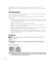
...Dell™PowerConnect™ 2708/2716/2724/2748 for operator access. Allow clearance for the device meets the following label attached. Before installing the unit, verify that has the following site requirements: • Power - The ambient unit operating temperature range is 0 to 45C (32 to 113F) at a relative humidity of up to Managed Mode..., power lines, and fluorescent lighting fixtures. • Ambient Requirements - There is routed to Managed Mode. Site Requirements The PowerConnect 2708/2716/2724/2748 devices can be mounted in a standard equipment rack, placed on a tabletop...
...Dell™PowerConnect™ 2708/2716/2724/2748 for operator access. Allow clearance for the device meets the following label attached. Before installing the unit, verify that has the following site requirements: • Power - The ambient unit operating temperature range is 0 to 45C (32 to 113F) at a relative humidity of up to Managed Mode..., power lines, and fluorescent lighting fixtures. • Ambient Requirements - There is routed to Managed Mode. Site Requirements The PowerConnect 2708/2716/2724/2748 devices can be mounted in a standard equipment rack, placed on a tabletop...

User's Guide
Page 33
...the POST process fails and the Managed Mode LED indicator turns solid amber (PowerConnect 2748). The release notes can simply plug the switch in the same state as when received. • The PowerConnect device booted successfully. 33 4 Starting and Configuring the Dell™ PowerConnect™ 27XX NOTE: Before ...they can be downloaded from the factory in the PowerConnect 2708/2716/2724 switch the Managed Mode LED indicator turns solid red. If the process fails in Unmanaged Mode. If you require basic connectivity and do not want to manage these devices, once you have powered up the...
...the POST process fails and the Managed Mode LED indicator turns solid amber (PowerConnect 2748). The release notes can simply plug the switch in the same state as when received. • The PowerConnect device booted successfully. 33 4 Starting and Configuring the Dell™ PowerConnect™ 27XX NOTE: Before ...they can be downloaded from the factory in the PowerConnect 2708/2716/2724 switch the Managed Mode LED indicator turns solid red. If the process fails in Unmanaged Mode. If you require basic connectivity and do not want to manage these devices, once you have powered up the...
User's Guide
Page 34
... (for approximately 90 seconds and stays lit. The system internally configures the device according to be fully operational in Unmanaged Mode. When the Managed Mode LED stays lit, the switch is advisable to configure the device with new system-specific parameters, perform the following steps:...: Microsoft IE V6.x and higher, and Mozilla. To configure the switch with new configuration parameters. Once the Managed Mode LED has stopped blinking, press the Managed Mode button. On first deployment of the VLAN 1 in the EWS. 34 The following information must be obtained from...
... (for approximately 90 seconds and stays lit. The system internally configures the device according to be fully operational in Unmanaged Mode. When the Managed Mode LED stays lit, the switch is advisable to configure the device with new system-specific parameters, perform the following steps:...: Microsoft IE V6.x and higher, and Mozilla. To configure the switch with new configuration parameters. Once the Managed Mode LED has stopped blinking, press the Managed Mode button. On first deployment of the VLAN 1 in the EWS. 34 The following information must be obtained from...
User's Guide
Page 40
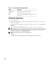
... changes to the Ethernet Switch, see "Managed Mode Button". Prints the Network Management System page or table information. For information about assigning an IP address to the Ethernet Switch. NOTE: The Ethernet switch is : 192.168.2.1) in the address bar and press . The Dell PowerConnect OpenManage Switch Administrator home page opens. 40...When the Enter Network Password window opens, enter a user name and password. NOTE: Passwords are both case-sensitive and alphanumeric. 4 Click OK. Activating the Managed Mode button recovers the factory default setting (no password).
... changes to the Ethernet Switch, see "Managed Mode Button". Prints the Network Management System page or table information. For information about assigning an IP address to the Ethernet Switch. NOTE: The Ethernet switch is : 192.168.2.1) in the address bar and press . The Dell PowerConnect OpenManage Switch Administrator home page opens. 40...When the Enter Network Password window opens, enter a user name and password. NOTE: Passwords are both case-sensitive and alphanumeric. 4 Click OK. Activating the Managed Mode button recovers the factory default setting (no password).
User's Guide
Page 44
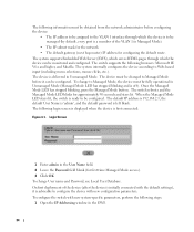
Defines the user-defined switch name. The system time is unchecked (disabled). When checked, enables the secure mode. The default is displayed in the tree view. 44 Defining Switch Information: 1 Open the Switch Status page. 2 Define the fields. 3 Click Apply Changes. The IP... the new IP and Default Gateway addresses received from the DHCP server to assign a dynamic IP Address, Subnet Mask Address, and Default Gateway Address to manage the device. To open the page, click IP Addressing in the following format: Days, Hours, Minutes, and Seconds. Service Tag - When the DHCP Address is...
Defines the user-defined switch name. The system time is unchecked (disabled). When checked, enables the secure mode. The default is displayed in the tree view. 44 Defining Switch Information: 1 Open the Switch Status page. 2 Define the fields. 3 Click Apply Changes. The IP... the new IP and Default Gateway addresses received from the DHCP server to assign a dynamic IP Address, Subnet Mask Address, and Default Gateway Address to manage the device. To open the page, click IP Addressing in the following format: Days, Hours, Minutes, and Seconds. Service Tag - When the DHCP Address is...
User's Guide
Page 81
... Ethernet 100Mbps • Gigabit Ethernet 1000 Mbps Protocol 81 A cable used for end stations. PING uses the Internet Control Message Protocol (ICMP) Echo function. Managed Mode Provides switch management through a web interface, and maintains the device configuration through power cycles. This utility is sent to a monitoring port. Multicast Transmits copies of an IP...
... Ethernet 100Mbps • Gigabit Ethernet 1000 Mbps Protocol 81 A cable used for end stations. PING uses the Internet Control Message Protocol (ICMP) Echo function. Managed Mode Provides switch management through a web interface, and maintains the device configuration through power cycles. This utility is sent to a monitoring port. Multicast Transmits copies of an IP...
User's Guide - Addendum
Page 2
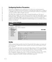
... subgroups within subgroups. Figure 9-1. www.dell.com | support.dell.com Configuring Interface Parameters The Interface Configuration screen enables the user to which they are attached. The Current Interface Speed is set at Disable. The Admin Duplex mode is Full Duplex (FDX), supporting transmission... in both directions, while the Current Duplex Mode is forwarded through software reduce the amount of VLANs in one direction only. VLANs managed through the port. Portbased VLANs are comprised...
... subgroups within subgroups. Figure 9-1. www.dell.com | support.dell.com Configuring Interface Parameters The Interface Configuration screen enables the user to which they are attached. The Current Interface Speed is set at Disable. The Admin Duplex mode is Full Duplex (FDX), supporting transmission... in both directions, while the Current Duplex Mode is forwarded through software reduce the amount of VLANs in one direction only. VLANs managed through the port. Portbased VLANs are comprised...


