Readme
Page 4
... test result as Short Cable for ports G1G44 and Unknown for G45-G48. The login screen accepts any password for default username Description The Browse button is not mentioned in help file for HTTP downloads. PowerConnect 2748 Release Notes Known Restrictions and Limitations... Integrated Cable Test Title Inconsistent Integrated Cable Test results Incorrect cable test result for the combo ports (shorted cable) Description Testing the integrated cable with the ...
... test result as Short Cable for ports G1G44 and Unknown for G45-G48. The login screen accepts any password for default username Description The Browse button is not mentioned in help file for HTTP downloads. PowerConnect 2748 Release Notes Known Restrictions and Limitations... Integrated Cable Test Title Inconsistent Integrated Cable Test results Incorrect cable test result for the combo ports (shorted cable) Description Testing the integrated cable with the ...

User's Guide
Page 3
... 11 Layer 2 Features 11 VLAN Supported Features 12 Class of Service (CoS) Features 12 Ethernet Switch Management Features 13 Port Default Settings 13 2 Hardware Description Switch Port Configurations 15 PowerConnect 2708/2716/2724/2748 Front Panel Port Description . . . . 15 Physical Dimensions 19 LED Definitions 19 Power LED 19 Managed Mode LED 19 Fan LED (2748...
... 11 Layer 2 Features 11 VLAN Supported Features 12 Class of Service (CoS) Features 12 Ethernet Switch Management Features 13 Port Default Settings 13 2 Hardware Description Switch Port Configurations 15 PowerConnect 2708/2716/2724/2748 Front Panel Port Description . . . . 15 Physical Dimensions 19 LED Definitions 19 Power LED 19 Managed Mode LED 19 Fan LED (2748...

User's Guide
Page 5
... Downloading Files From Server 55 Downloading Files From Server 55 Local User Database 60 Integrated Cable Test for Copper Cables 61 Optical Transceivers Diagnostics 63 Port Mirroring 64 Enabling Storm Control 65 7 Configuring Quality of Service Quality of Service (QoS) Overview 69 CoS Services 70 Defining CoS Settings 71 Configuring QoS...
... Downloading Files From Server 55 Downloading Files From Server 55 Local User Database 60 Integrated Cable Test for Copper Cables 61 Optical Transceivers Diagnostics 63 Port Mirroring 64 Enabling Storm Control 65 7 Configuring Quality of Service Quality of Service (QoS) Overview 69 CoS Services 70 Defining CoS Settings 71 Configuring QoS...
User's Guide
Page 7
... the small to minimize administrative management effort, while enhancing and improving network traffic control. The switches are ideal for installing, configuring and maintaining the PowerConnect 2708, PowerConnect 2716, PowerConnect 2724, and PowerConnect 2748 Webmanaged Gigabit Ethernet switches. Figure 1-1. These PowerConnect devices are managed by Dell's OpenManage Switch Administrator. 8 1-Gigabit Ethernet Ports The following figure illustrates the PowerConnect 2708 front panel.
... the small to minimize administrative management effort, while enhancing and improving network traffic control. The switches are ideal for installing, configuring and maintaining the PowerConnect 2708, PowerConnect 2716, PowerConnect 2724, and PowerConnect 2748 Webmanaged Gigabit Ethernet switches. Figure 1-1. These PowerConnect devices are managed by Dell's OpenManage Switch Administrator. 8 1-Gigabit Ethernet Ports The following figure illustrates the PowerConnect 2708 front panel.
User's Guide
Page 8
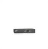
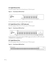
...). 48 1-Gigabit Ethernet Ports The following figure illustrates the PowerConnect 2716 front panel. Figure 1-2. 16 1-Gigabit Ethernet Ports The following figure illustrates the PowerConnect 2748 front panel. Figure 1-3. PowerConnect 2748 Front Panel 8 PowerConnect 2716 Front Panel The PowerConnect 2716 switch supports 16 GbE copper ports. 24 1-Gigabit Ethernet Ports + 2 SFP Combo ports The following figure illustrates the PowerConnect 2724 front panel.
...). 48 1-Gigabit Ethernet Ports The following figure illustrates the PowerConnect 2716 front panel. Figure 1-2. 16 1-Gigabit Ethernet Ports The following figure illustrates the PowerConnect 2748 front panel. Figure 1-3. PowerConnect 2748 Front Panel 8 PowerConnect 2716 Front Panel The PowerConnect 2716 switch supports 16 GbE copper ports. 24 1-Gigabit Ethernet Ports + 2 SFP Combo ports The following figure illustrates the PowerConnect 2724 front panel.

User's Guide
Page 9
...address to the switch so that it becomes inaccessible. In Secure Mode the switch retains configuration through power cycles. However, this feature on a port where the HOL blocking prevention mechanism is active at Half Duplex only. 9 Operates independent of the queue. From Managed Mode, when the Managed...• Managed Mode - The switch does not have an IP address, nor is pressed, the switch enters Unmanaged Mode. • Secure Mode (PowerConnect 2748 only) - Once enabled, it is set to Secure Mode via the web interface. The user may enable or disable this applies to the ...
...address to the switch so that it becomes inaccessible. In Secure Mode the switch retains configuration through power cycles. However, this feature on a port where the HOL blocking prevention mechanism is active at Half Duplex only. 9 Operates independent of the queue. From Managed Mode, when the Managed...• Managed Mode - The switch does not have an IP address, nor is pressed, the switch enters Unmanaged Mode. • Secure Mode (PowerConnect 2748 only) - Once enabled, it is set to Secure Mode via the web interface. The user may enable or disable this applies to the ...
User's Guide
Page 10
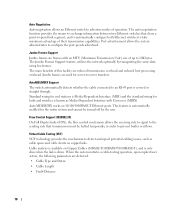
.../MDIX works on Copper Cables (10BASE-T/100BASE-T/1000BASE-T), and is only done when the link is available on 10/100/1000BASE-T Ethernet ports. Flow Control Support (IEEE802.3X) On Full Duplex links (FDX), the flow control mechanism allows the receiving side to signal to ... feature, utilizes the network optimally by the user. AutoMDI/MDIX Support The switch automatically detects whether the cable connected to configure the port speeds advertised. Jumbo Frames Support Jumbo frames are reduced transmission overhead and reduced host processing overhead. Jumbo frames are detected: •...
.../MDIX works on Copper Cables (10BASE-T/100BASE-T/1000BASE-T), and is only done when the link is available on 10/100/1000BASE-T Ethernet ports. Flow Control Support (IEEE802.3X) On Full Duplex links (FDX), the flow control mechanism allows the receiving side to signal to ... feature, utilizes the network optimally by the user. AutoMDI/MDIX Support The switch automatically detects whether the cable connected to configure the port speeds advertised. Jumbo Frames Support Jumbo frames are reduced transmission overhead and reduced host processing overhead. Jumbo frames are detected: •...

User's Guide
Page 11
... forwarded by learning them from the incoming frames source address. Storm Control Storm Control enables limiting the amount of all ports on their destination MAC address). Unmanaged Mode Classic Bridging In Unmanaged Mode, the switch performs classic bridging. The MAC .... Automatic Aging for untagged frames. Layer 2 Features Port Mirroring The port mirroring mechanism monitors and mirrors network traffic by forwarding copies of 16K MAC addresses. MAC Address Supported Features MAC Address Capacity Support The PowerConnect 2708, 2716, and 2724 switches support a total of 8K...
... forwarded by learning them from the incoming frames source address. Storm Control Storm Control enables limiting the amount of all ports on their destination MAC address). Unmanaged Mode Classic Bridging In Unmanaged Mode, the switch performs classic bridging. The MAC .... Automatic Aging for untagged frames. Layer 2 Features Port Mirroring The port mirroring mechanism monitors and mirrors network traffic by forwarding copies of 16K MAC addresses. MAC Address Supported Features MAC Address Capacity Support The PowerConnect 2708, 2716, and 2724 switches support a total of 8K...

User's Guide
Page 12
... VLAN Supported Features VLAN Support VLANs are collections of Service (CoS) Features The PowerConnect 2708/2716/2724/2748 system enables users to all ports on -going process. Port Based Virtual LANs (VLANs) Port-based VLANs classify incoming packets to a VLAN based on either the VLAN tag or based on a combination of service. The switch can...
... VLAN Supported Features VLAN Support VLANs are collections of Service (CoS) Features The PowerConnect 2708/2716/2724/2748 system enables users to all ports on -going process. Port Based Virtual LANs (VLANs) Port-based VLANs classify incoming packets to a VLAN based on either the VLAN tag or based on a combination of service. The switch can...
User's Guide
Page 13
... (RMON) is an extension to the Simple Network Management Protocol (SNMP), which the system can classify according to IPv4 information (DSCP). Port Default Settings The PowerConnect 2708/2716/2724/2748 devices's port default settings are established or enforced. A CoS is defined by the user, whereby packets are related to the same Class of the...
... (RMON) is an extension to the Simple Network Management Protocol (SNMP), which the system can classify according to IPv4 information (DSCP). Port Default Settings The PowerConnect 2708/2716/2724/2748 devices's port default settings are established or enforced. A CoS is defined by the user, whereby packets are related to the same Class of the...

User's Guide
Page 15
... front panel for connecting to indicate the port status. On each port there are numbered 1 to right. The Power LED on or not. 2 Hardware Description Switch Port Configurations PowerConnect 2708/2716/2724/2748 Front Panel Port Description The Dell™ PowerConnect™ 2708, 2716, 2724 and 2748 switches use 10/100/1000BASE-T ports on the front panel, restores the device...
... front panel for connecting to indicate the port status. On each port there are numbered 1 to right. The Power LED on or not. 2 Hardware Description Switch Port Configurations PowerConnect 2708/2716/2724/2748 Front Panel Port Description The Dell™ PowerConnect™ 2708, 2716, 2724 and 2748 switches use 10/100/1000BASE-T ports on the front panel, restores the device...

User's Guide
Page 16
...On the front panel, there are 16 ports, which indicates the Ethernet switch operational status. Figure 2-2. PowerConnect 2708 Back Panel Figure 2-3. The Power LED on the front panel indicates whether the device is the Managed Mode LED which are LEDs to indicate the port status. On the left to 16, top...and left side of the front panel is powered on the front panel, restores the device's default settings configuration. Figure 2-4. On each port there are numbered 1 to right. A Managed Mode push-button, located on the right side on or not. PowerConnect 2716 Back Panel 16
...On the front panel, there are 16 ports, which indicates the Ethernet switch operational status. Figure 2-2. PowerConnect 2708 Back Panel Figure 2-3. The Power LED on the front panel indicates whether the device is the Managed Mode LED which are LEDs to indicate the port status. On the left to 16, top...and left side of the front panel is powered on the front panel, restores the device's default settings configuration. Figure 2-4. On each port there are numbered 1 to right. A Managed Mode push-button, located on the right side on or not. PowerConnect 2716 Back Panel 16

User's Guide
Page 17
... RJ-45 and SFP ports are two SFP (Small Form-Factor Plugable) ports, designated as ports 23 and 24, for swappable optical transceiver, which are LEDs to right. There are present, the SFP port will be the active port, whereas the RJ-45 port will be used . PowerConnect 2724 Front Panel On ...the front panel there are 24 ports which offers high...
... RJ-45 and SFP ports are two SFP (Small Form-Factor Plugable) ports, designated as ports 23 and 24, for swappable optical transceiver, which are LEDs to right. There are present, the SFP port will be the active port, whereas the RJ-45 port will be used . PowerConnect 2724 Front Panel On ...the front panel there are 24 ports which offers high...

User's Guide
Page 18
... are determined by the physical connection used on a combo port, and utilizes the information in all the control interfaces. On the top right side of the PowerConnect 2748 device. PowerConnect 2748 Front Panel On the front panel, there are LEDs to the SFP (or vice versa) without resetting the device. The system automatically... fan operations status and the Power LED on the front panel indicates whether the device is the Managed Mode LED, which are present, the SFP port will be the active port, whereas the RJ-45 port will be used at any one time. PowerConnect 2748 Back Panel 18
... are determined by the physical connection used on a combo port, and utilizes the information in all the control interfaces. On the top right side of the PowerConnect 2748 device. PowerConnect 2748 Front Panel On the front panel, there are LEDs to the SFP (or vice versa) without resetting the device. The system automatically... fan operations status and the Power LED on the front panel indicates whether the device is the Managed Mode LED, which are present, the SFP port will be the active port, whereas the RJ-45 port will be used at any one time. PowerConnect 2748 Back Panel 18
User's Guide
Page 20
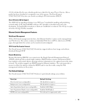
... valid image. Speed/Link/Activity is indicated on the right LED. Fan LED (2748 only) On the PowerConnect 2748 front panel there is a fan LED. Port LEDs 10/100/1000BASE-T Port LEDs Each 10/100/1000BASE-T port has two LEDs. Figure 2-9. Table 2-3. Table 2-2. Managed Mode LED Indications LED Color Green Flashing Green Solid Amber...
... valid image. Speed/Link/Activity is indicated on the right LED. Fan LED (2748 only) On the PowerConnect 2748 front panel there is a fan LED. Port LEDs 10/100/1000BASE-T Port LEDs Each 10/100/1000BASE-T port has two LEDs. Figure 2-9. Table 2-3. Table 2-2. Managed Mode LED Indications LED Color Green Flashing Green Solid Amber...

User's Guide
Page 21
...PowerConnect 2708/2716/2724/2748 has a Managed Mode push button on the front panel. RJ-45 Copper based 10/100/ 1000BASE-T LED Indications LED Color Left LED Green Static Green Flashing Amber Static Amber Flashing Off Right LED Green Static Off Description The port is occurring. SFP Port... indications. Off No link is established. SFP LED Indications LED Color Description Green Static Link is established. Table 2-4. The port is for changing between Managed Mode and Unmanaged (or Secure) Mode. The Managed Mode button is transmitting or receiving data at ...
...PowerConnect 2708/2716/2724/2748 has a Managed Mode push button on the front panel. RJ-45 Copper based 10/100/ 1000BASE-T LED Indications LED Color Left LED Green Static Green Flashing Amber Static Amber Flashing Off Right LED Green Static Off Description The port is occurring. SFP Port... indications. Off No link is established. SFP LED Indications LED Color Description Green Static Link is established. Table 2-4. The port is for changing between Managed Mode and Unmanaged (or Secure) Mode. The Managed Mode button is transmitting or receiving data at ...
User's Guide
Page 22
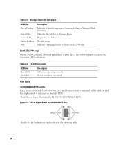
... Pinout Information This section explains the switch physical interfaces, and provides information about cables and port connections. Ports, Connectors and Cables Connector Port/Interface RJ-45 10/100/1000BASE-T Port Cable Cat.5 The following table. 22 The PowerConnect 2708 and PowerConnect 2716 devices have no internal fans. The Category 5e specification includes test parameters that are used...
... Pinout Information This section explains the switch physical interfaces, and provides information about cables and port connections. Ports, Connectors and Cables Connector Port/Interface RJ-45 10/100/1000BASE-T Port Cable Cat.5 The following table. 22 The PowerConnect 2708 and PowerConnect 2716 devices have no internal fans. The Category 5e specification includes test parameters that are used...
User's Guide
Page 23
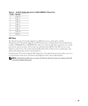
...The system automatically detects the media used at any time. SFP Ports The PowerConnect 2724 switch supports two SFP transceivers combo ports, and the PowerConnect 2748 switch supports four SFP transceivers combo ports for 10/100/ 1000BASE-T Ethernet Port Pin No Function 1 TxRx 1+ 2 TxRx 1- 3 TxRx 2+... TxRx 4- The system can be used on a combo port, and utilizes this information in the control interfaces. PowerConnect 2724 switch supports SFP diagnostics. The optical transceiver provides access to a set of a combo port can switch from the RJ-45 to the system administrator. ...
...The system automatically detects the media used at any time. SFP Ports The PowerConnect 2724 switch supports two SFP transceivers combo ports, and the PowerConnect 2748 switch supports four SFP transceivers combo ports for 10/100/ 1000BASE-T Ethernet Port Pin No Function 1 TxRx 1+ 2 TxRx 1- 3 TxRx 2+... TxRx 4- The system can be used on a combo port, and utilizes this information in the control interfaces. PowerConnect 2724 switch supports SFP diagnostics. The optical transceiver provides access to a set of a combo port can switch from the RJ-45 to the system administrator. ...

User's Guide
Page 25
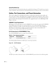
...only with a lighting bolt may cause electrical shock. If the user wishes to make cable and port connections for the PowerConnect 2708, 2716, 2724, and 2748 devices. Opening or removing covers marked with a triangular symbol with ...approved equipment. • Allow the Ethernet device to cool before performing the procedures in this section: • Observe and follow the safety instructions located in the Product Information Guide. 3 Installing the Dell™ PowerConnect...
...only with a lighting bolt may cause electrical shock. If the user wishes to make cable and port connections for the PowerConnect 2708, 2716, 2724, and 2748 devices. Opening or removing covers marked with a triangular symbol with ...approved equipment. • Allow the Ethernet device to cool before performing the procedures in this section: • Observe and follow the safety instructions located in the Product Information Guide. 3 Installing the Dell™ PowerConnect...

User's Guide
Page 32
... (systems, servers, switches or routers) that the device is turned off on the ports, a straight through twisted-pair cables can be used to connect to any other end to a switch or server.... 2 Make sure each port on the device is illuminated indicating that conform to a power source, confirm that supports auto-negotiation...As each connection is made, the (green or amber) Link LED corresponding to an uplink port, use Category 5 Unshielded Twisted-Pair (UTP) cables with RJ-45 connectors that the connection is valid. 32 Figure...
... (systems, servers, switches or routers) that the device is turned off on the ports, a straight through twisted-pair cables can be used to connect to any other end to a switch or server.... 2 Make sure each port on the device is illuminated indicating that conform to a power source, confirm that supports auto-negotiation...As each connection is made, the (green or amber) Link LED corresponding to an uplink port, use Category 5 Unshielded Twisted-Pair (UTP) cables with RJ-45 connectors that the connection is valid. 32 Figure...


