
Reference and Installation Guide (.pdf)
Page 7
...remove options inside the computer, such as dual in-line memory modules (DIMMs), expansion cards, or drives. • Appendix A, "Technical Specifications," is intended primarily as follows: • Everyone should read Chapter 1, "Introduction," for setting up your computer system. This chapter describes the... products from parts and components that are new or equivalent to new in which regulatory agencies have tested and approved the Dell OptiPlex Gn or Gn+ low-profile systems. • Appendix D, "Warranties and Return Policy," describes the warranty for users who are summarized as...
...remove options inside the computer, such as dual in-line memory modules (DIMMs), expansion cards, or drives. • Appendix A, "Technical Specifications," is intended primarily as follows: • Everyone should read Chapter 1, "Introduction," for setting up your computer system. This chapter describes the... products from parts and components that are new or equivalent to new in which regulatory agencies have tested and approved the Dell OptiPlex Gn or Gn+ low-profile systems. • Appendix D, "Warranties and Return Policy," describes the warranty for users who are summarized as...
Reference and Installation Guide (.pdf)
Page 8
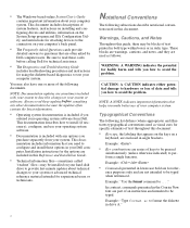
...." NOTE: Documentation updates are used in angle brackets. CAUTION: A CAUTION indicates either potential damage to provide last-minute updates about your Dell computer. ence purposes only and are series of system features, instructions on installing and configuring drivers and utilities, information on the System Setup...guide, there may also have one or more of the following subsections describe notational conventions used as visual cues for specific elements of data and tells you how to the connectors on your system or software. These blocks are warnings, ...
...." NOTE: Documentation updates are used in angle brackets. CAUTION: A CAUTION indicates either potential damage to provide last-minute updates about your Dell computer. ence purposes only and are series of system features, instructions on installing and configuring drivers and utilities, information on the System Setup...guide, there may also have one or more of the following subsections describe notational conventions used as visual cues for specific elements of data and tells you how to the connectors on your system or software. These blocks are warnings, ...
Reference and Installation Guide (.pdf)
Page 14
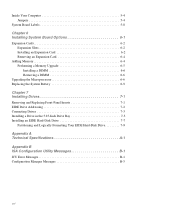
... 7-3 Installing a Drive in the 5.25-Inch Drive Bay 7-3 Installing an EIDE Hard-Disk Drive 7-7 Partitioning and Logically Formatting Your EIDE Hard-Disk Drive 7-9 Appendix A Technical Specifications A-1 Appendix B ISA Configuration Utility Messages B-1 ICU Error Messages B-1 Configuration Manager Messages B-5 xvi
... 7-3 Installing a Drive in the 5.25-Inch Drive Bay 7-3 Installing an EIDE Hard-Disk Drive 7-7 Partitioning and Logically Formatting Your EIDE Hard-Disk Drive 7-9 Appendix A Technical Specifications A-1 Appendix B ISA Configuration Utility Messages B-1 ICU Error Messages B-1 Configuration Manager Messages B-5 xvi
Reference and Installation Guide (.pdf)
Page 17
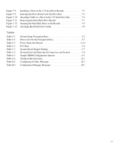
... Keys 2-7 Power Time-Out Periods 2-10 ICU Keys 3-4 System-Board Jumper Settings 5-7 System Board and Riser Board Connectors and Sockets 5-8 Sample DIMM Configuration Options 6-5 Technical Specifications A-1 Configuration Utility Messages B-1 Configuration Manager Messages B-5 xix Table A-1. Table B-2. Figure 7-10. Installing a Drive in the 5.25-Inch Drive Bracket 7-5 Inserting the Drive Bracket into the...
... Keys 2-7 Power Time-Out Periods 2-10 ICU Keys 3-4 System-Board Jumper Settings 5-7 System Board and Riser Board Connectors and Sockets 5-8 Sample DIMM Configuration Options 6-5 Technical Specifications A-1 Configuration Utility Messages B-1 Configuration Manager Messages B-5 xix Table A-1. Table B-2. Figure 7-10. Installing a Drive in the 5.25-Inch Drive Bracket 7-5 Inserting the Drive Bracket into the...
Reference and Installation Guide (.pdf)
Page 19
...and installation, file updates, and asset tracking after hours and on from a server management console. The Pentium microprocessor with PCI specification 2.1. • Full Plug and Play version 1.0a capability, which greatly simplifies the installation of expansion cards. Cache memory enhances ... it. NOTE: The key combination is recommended. The use of your hard-disk drive has become unreliable. Chapter 1 Introduction Dell® OptiPlex® Gn and Gn+ low-profile systems are SMART-compliant. • Full compliance with MMX technology has a 16-kilobyte (KB) internal data ...
...and installation, file updates, and asset tracking after hours and on from a server management console. The Pentium microprocessor with PCI specification 2.1. • Full Plug and Play version 1.0a capability, which greatly simplifies the installation of expansion cards. Cache memory enhances ... it. NOTE: The key combination is recommended. The use of your hard-disk drive has become unreliable. Chapter 1 Introduction Dell® OptiPlex® Gn and Gn+ low-profile systems are SMART-compliant. • Full compliance with MMX technology has a 16-kilobyte (KB) internal data ...
Reference and Installation Guide (.pdf)
Page 30
... by drive-type number, entered individually from Dell) • None • USR1 or USR2 • A specific drive-type number NOTE: Operating systems that bypass the system BIOS may not obtain optimum hard-disk drive performance. 2-4 Dell OptiPlex Gn and Gn+ Low-Profile Systems Reference and Installation Guide Drives... EIDE devices from the keyboard or set the appropriate Drive category to decrease the number. To choose a setting for these categories, type characters from Dell that follow (month, day-of-month, and year). The options are: • 5.25 Inch, 360 KB • 5.25 Inch, 1.2...
... by drive-type number, entered individually from Dell) • None • USR1 or USR2 • A specific drive-type number NOTE: Operating systems that bypass the system BIOS may not obtain optimum hard-disk drive performance. 2-4 Dell OptiPlex Gn and Gn+ Low-Profile Systems Reference and Installation Guide Drives... EIDE devices from the keyboard or set the appropriate Drive category to decrease the number. To choose a setting for these categories, type characters from Dell that follow (month, day-of-month, and year). The options are: • 5.25 Inch, 360 KB • 5.25 Inch, 1.2...
Reference and Installation Guide (.pdf)
Page 49
... use this chapter. You can only view the resources currently assigned and lock or unlock them. You should lock a card only if it cannot use specific resource values. See "Locking and Unlocking Cards" found later in the ICU database). NOTE: You cannot modify the resources of these buttons, a smaller Specify list...
... use this chapter. You can only view the resources currently assigned and lock or unlock them. You should lock a card only if it cannot use specific resource values. See "Locking and Unlocking Cards" found later in the ICU database). NOTE: You cannot modify the resources of these buttons, a smaller Specify list...

Reference and Installation Guide (.pdf)
Page 55
... with Administrator privileges. Start the Windows NT operating system, and log in Chapter 2 for use on administrative users and privileges, see your specific network. Insert the NIC driver diskette 2 into drive A, type a:\, and then click OK. Select 3Com Fast EtherLink XL NIC (3C905)... double-click the Network icon. 3. Verify that the NIC is enabled in this chapter for more information. 4. See "NIC" in the Dell Accessories program group) to Requires Disk From Manufacturer, and click Continue. 10. Double-click My Computer, double-click Control Panel, and then...
... with Administrator privileges. Start the Windows NT operating system, and log in Chapter 2 for use on administrative users and privileges, see your specific network. Insert the NIC driver diskette 2 into drive A, type a:\, and then click OK. Select 3Com Fast EtherLink XL NIC (3C905)... double-click the Network icon. 3. Verify that the NIC is enabled in this chapter for more information. 4. See "NIC" in the Dell Accessories program group) to Requires Disk From Manufacturer, and click Continue. 10. Double-click My Computer, double-click Control Panel, and then...
Reference and Installation Guide (.pdf)
Page 56
...for detailed instructions. 3. Start the Windows for the el90x.386 driver, type a:\wfw311 and click OK to load the Network Driver Interface Specification (NDIS) 3 driver. Select Unlisted or Updated Network Adapter, and click OK. 12. If the Install Driver dialog box appears and ...for Workgroups NIC Driver To connect your system to and configure it for information on using the NDIS 2 driver with Windows 95. 4-4 Dell OptiPlex Gn and Gn+ Low-ProfileSystems Reference and Installation Guide Double-click the System icon to access the Windows Setup screen. 7. From the Network Setup window...
...for detailed instructions. 3. Start the Windows for the el90x.386 driver, type a:\wfw311 and click OK to load the Network Driver Interface Specification (NDIS) 3 driver. Select Unlisted or Updated Network Adapter, and click OK. 12. If the Install Driver dialog box appears and ...for Workgroups NIC Driver To connect your system to and configure it for information on using the NDIS 2 driver with Windows 95. 4-4 Dell OptiPlex Gn and Gn+ Low-ProfileSystems Reference and Installation Guide Double-click the System icon to access the Windows Setup screen. 7. From the Network Setup window...
Reference and Installation Guide (.pdf)
Page 80
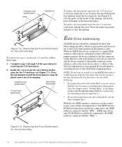
...up to the middle connector on the interface cable is the slave device (drive 1). Removing the Front-Panel Insert for the 3.5-Inch Bay 7-2 Dell OptiPlex Gn and Gn+ Low-Profile Systems Reference and Installation Guide EIDE hard-disk drives should be connected to the EIDE interface connector labeled "IDE1." (EIDE tape drives... the device attached to the last connector on the interface cable is a different type from the first drive but you do not have the specifications for the first drive, do one of the following: • If you want to snap the plastic insert out of the insert into the...
...up to the middle connector on the interface cable is the slave device (drive 1). Removing the Front-Panel Insert for the 3.5-Inch Bay 7-2 Dell OptiPlex Gn and Gn+ Low-Profile Systems Reference and Installation Guide EIDE hard-disk drives should be connected to the EIDE interface connector labeled "IDE1." (EIDE tape drives... the device attached to the last connector on the interface cable is a different type from the first drive but you do not have the specifications for the first drive, do one of the following: • If you want to snap the plastic insert out of the insert into the...
Reference and Installation Guide (.pdf)
Page 89
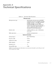
...-KB instruction cache) Math coprocessor internal to microprocessor System Information System chip set through the System Setup program. Appendix A Technical Specifications Table A-1. Design provides for future Dell-supported upgrades. Technical Specifications A-1 Technical Specifications Microprocessor Microprocessor type Intel Pentium microprocessor with MMX technology that runs at 166 MHz internally/ 66 MHz externally, at 200 MHz...
...-KB instruction cache) Math coprocessor internal to microprocessor System Information System chip set through the System Setup program. Appendix A Technical Specifications Table A-1. Design provides for future Dell-supported upgrades. Technical Specifications A-1 Technical Specifications Microprocessor Microprocessor type Intel Pentium microprocessor with MMX technology that runs at 166 MHz internally/ 66 MHz externally, at 200 MHz...

Reference and Installation Guide (.pdf)
Page 90
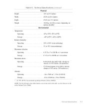
A-2 Dell OptiPlex Gn and Gn+ Low-Profile Systems Reference and Installation Guide Table A-1. Technical Specifications (continued) Expansion Bus Bus types PCI (version 2.1) and ISA Bus speed: PCI 33 MHz ISA 8.33 MHz PCI expansion-card connectors two (one shares a card-...
A-2 Dell OptiPlex Gn and Gn+ Low-Profile Systems Reference and Installation Guide Table A-1. Technical Specifications (continued) Expansion Bus Bus types PCI (version 2.1) and ISA Bus speed: PCI 33 MHz ISA 8.33 MHz PCI expansion-card connectors two (one shares a card-...
Reference and Installation Guide (.pdf)
Page 91
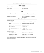
Technical Specifications A-3 Table A-1. Technical Specifications (continued) Memory (continued) Maximum RAM 256 MB Cache memory 512-KB L2 cache BIOS address F0000h Drives Externally accessible bays one 15-hole connector PS/2-...
Technical Specifications A-3 Table A-1. Technical Specifications (continued) Memory (continued) Maximum RAM 256 MB Cache memory 512-KB L2 cache BIOS address F0000h Drives Externally accessible bays one 15-hole connector PS/2-...
Reference and Installation Guide (.pdf)
Page 92
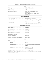
Table A-1. Technical Specifications (continued) Video Video type S3 Trio64V2 controller Video memory 2 MB Maximum resolutions 1280 x 1024 pixels with 256 colors noninterlaced 1024 x 768 pixels with 65,536 colors noninterlaced Key Combinations
Table A-1. Technical Specifications (continued) Video Video type S3 Trio64V2 controller Video memory 2 MB Maximum resolutions 1280 x 1024 pixels with 256 colors noninterlaced 1024 x 768 pixels with 65,536 colors noninterlaced Key Combinations
Reference and Installation Guide (.pdf)
Page 93
Technical Specifications A-5 Technical Specifications (continued) Physical Height 10.9 cm (4.3 inches) Width 40.89 cm (16.1 inches) Depth 43.69 cm (17.2 inches) Weight 10.89 kg (24.0 lb) or ...
Technical Specifications A-5 Technical Specifications (continued) Physical Height 10.9 cm (4.3 inches) Width 40.89 cm (16.1 inches) Depth 43.69 cm (17.2 inches) Weight 10.89 kg (24.0 lb) or ...
Reference and Installation Guide (.pdf)
Page 105
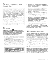
...your system. VCCI Notices (Japan Only) Most Dell computer systems are classified by the Voluntary Control Council for Interference (VCCI) as described in accordance with the preceding standards has been made and is on the specification label. If all steps necessary to remove sources ... as Class B information technology equipment (ITE). CE Notice Marking by Dell Computer Corporation could void your entire system is a Class A product. Note that VCCI regulations provide that it is specifically stated that changes or modifications not expressly approved by the symbol indicates ...
...your system. VCCI Notices (Japan Only) Most Dell computer systems are classified by the Voluntary Control Council for Interference (VCCI) as described in accordance with the preceding standards has been made and is on the specification label. If all steps necessary to remove sources ... as Class B information technology equipment (ITE). CE Notice Marking by Dell Computer Corporation could void your entire system is a Class A product. Note that VCCI regulations provide that it is specifically stated that changes or modifications not expressly approved by the symbol indicates ...
Reference and Installation Guide (.pdf)
Page 109
...in your Diagnostics and Troubleshooting Guide or the section titled "Contacting Dell" in the Dell factory; You must call Dell's Customer Technical Support within the warranty period. Shipments to Dell's facility. Dell does not accept liability for portable computers are returned to other storage...will issue a Return Material Authorization Number. If Dell repairs or replaces a product, its hardware products from defects in the following categories: software; This warranty does not cover any removable media, such as specifically noted); To request warranty service, you ship ...
...in your Diagnostics and Troubleshooting Guide or the section titled "Contacting Dell" in the Dell factory; You must call Dell's Customer Technical Support within the warranty period. Shipments to Dell's facility. Dell does not accept liability for portable computers are returned to other storage...will issue a Return Material Authorization Number. If Dell repairs or replaces a product, its hardware products from defects in the following categories: software; This warranty does not cover any removable media, such as specifically noted); To request warranty service, you ship ...
Reference and Installation Guide (.pdf)
Page 110
... MERCHANTABILITY AND FITNESS FOR A PARTICULAR PURPOSE. THESE WARRANTIES GIVE YOU SPECIFIC LEGAL RIGHTS, AND YOU MAY ALSO HAVE OTHER RIGHTS, WHICH VARY FROM STATE TO STATE (OR JURISDICTION). Dell will be made in effect on the date of the exchange. ...replaced parts, and your obligation to pay Dell for the Dell hardware product(s) covered under a written agreement with Dell, there may provide replacement parts made by various manufacturers when supplying parts to Dell. You must call Dell Customer D-2 Dell OptiPlex Gn and Gn+ Low-Profile Systems Reference and Installation ...
... MERCHANTABILITY AND FITNESS FOR A PARTICULAR PURPOSE. THESE WARRANTIES GIVE YOU SPECIFIC LEGAL RIGHTS, AND YOU MAY ALSO HAVE OTHER RIGHTS, WHICH VARY FROM STATE TO STATE (OR JURISDICTION). Dell will be made in effect on the date of the exchange. ...replaced parts, and your obligation to pay Dell for the Dell hardware product(s) covered under a written agreement with Dell, there may provide replacement parts made by various manufacturers when supplying parts to Dell. You must call Dell Customer D-2 Dell OptiPlex Gn and Gn+ Low-Profile Systems Reference and Installation ...
Reference and Installation Guide (.pdf)
Page 113
...-edge connector, 7-3 cautions, x COM port designations, 2-11 computer boot devices, 2-7 features, 1-1 illustrated, 5-5 precautions for working inside, 5-1 removing and replacing cover, 5-2 securing, 1-5 system board features, 1-2, 6-1 technical specifications, A-1 top-down view, 5-4 Configuration Manager, B-5 connectors card-edge, 7-3 control panel, 6-1 diskette/tape drive interface, 6-1 EIDE interface, 6-1 expansion-card, 6-2 Index 1 See AC Asset Tag category, 2-12...
...-edge connector, 7-3 cautions, x COM port designations, 2-11 computer boot devices, 2-7 features, 1-1 illustrated, 5-5 precautions for working inside, 5-1 removing and replacing cover, 5-2 securing, 1-5 system board features, 1-2, 6-1 technical specifications, A-1 top-down view, 5-4 Configuration Manager, B-5 connectors card-edge, 7-3 control panel, 6-1 diskette/tape drive interface, 6-1 EIDE interface, 6-1 expansion-card, 6-2 Index 1 See AC Asset Tag category, 2-12...
Reference and Installation Guide (.pdf)
Page 117
... (continued) socket release lever, 6-7 speeds, 2-6 types supported, A-1 monitor power management, 2-9 Mouse category, 2-10 mouse connector, 4-2, 6-1 MS-DOS network driver, 4-6 N NDIS 2 network driver, 4-6 Network Driver Interface Specification. See NDIS network drivers MS-DOS, 4-6 NDIS 2, 4-6 Windows 95, 4-6 Windows for Workgroups, 4-4 Windows NT 3.5x, 4-3 Windows NT 4.0, 4-2 network interface controller.
... (continued) socket release lever, 6-7 speeds, 2-6 types supported, A-1 monitor power management, 2-9 Mouse category, 2-10 mouse connector, 4-2, 6-1 MS-DOS network driver, 4-6 N NDIS 2 network driver, 4-6 Network Driver Interface Specification. See NDIS network drivers MS-DOS, 4-6 NDIS 2, 4-6 Windows 95, 4-6 Windows for Workgroups, 4-4 Windows NT 3.5x, 4-3 Windows NT 4.0, 4-2 network interface controller.


