
Quick Reference
Page 26
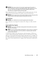
... Display Settings 1 After you can drag objects from voltage spikes that can occur during electrical storms or after power interruptions. Some surge protector manufacturers include warranty coverage for certain types of different devices. 26 Quick Reference Guide ...other end of viewable work space. Power Protection Devices Several devices are available to protect against power fluctuations and failures: • Surge protectors • Line conditioners • Uninterruptible power supplies (UPS) Surge Protectors Surge protectors and power strips equipped with a higher joule rating...
... Display Settings 1 After you can drag objects from voltage spikes that can occur during electrical storms or after power interruptions. Some surge protector manufacturers include warranty coverage for certain types of different devices. 26 Quick Reference Guide ...other end of viewable work space. Power Protection Devices Several devices are available to protect against power fluctuations and failures: • Surge protectors • Line conditioners • Uninterruptible power supplies (UPS) Surge Protectors Surge protectors and power strips equipped with a higher joule rating...
Quick Reference
Page 27
... protection. See the UPS manufacturer documentation for modem connection instructions. The battery charges while AC power is approved by nearby lightning strikes. When lightning occurs in data loss or file damage. Uninterruptible Power Supplies NOTICE: Loss of power while data is interrupted. Quick Reference Guide 27 See the surge protector documentation for information on...
... protection. See the UPS manufacturer documentation for modem connection instructions. The battery charges while AC power is approved by nearby lightning strikes. When lightning occurs in data loss or file damage. Uninterruptible Power Supplies NOTICE: Loss of power while data is interrupted. Quick Reference Guide 27 See the surge protector documentation for information on...

Quick Reference
Page 35
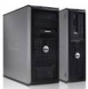
... section, follow the safety instructions in the Product Information Guide. CAUTION: To avoid electrical shock, always unplug your computer from the system board. 2 1 3 4 6 5 1 drives bay 2 power supply (CD/DVD, floppy, and hard drive) 3 system board 4 card slots 5 heat sink assembly 6 front I/O panel Quick Reference Guide 35 Inside View of Your Computer CAUTION...
... section, follow the safety instructions in the Product Information Guide. CAUTION: To avoid electrical shock, always unplug your computer from the system board. 2 1 3 4 6 5 1 drives bay 2 power supply (CD/DVD, floppy, and hard drive) 3 system board 4 card slots 5 heat sink assembly 6 front I/O panel Quick Reference Guide 35 Inside View of Your Computer CAUTION...

Quick Reference
Page 45
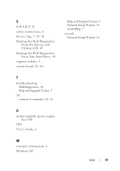
Inside View of Your Computer 3 2 1 1 floppy drive 3 power supply 5 heat sink assembly 6 2 optical drive 4 system board 6 hard drive 4 5 Quick Reference Guide 45
Inside View of Your Computer 3 2 1 1 floppy drive 3 power supply 5 heat sink assembly 6 2 optical drive 4 system board 6 hard drive 4 5 Quick Reference Guide 45
Quick Reference
Page 67
See UPS UPS User's Guide, 6 W warranty information, 6 Windows XP Index 67 S S.M.A.R.T, 56 safety instructions, 6 Service Tag, 7, 29, 38 Starting the Dell Diagnostics From the Drivers and Utilities CD, 49 Starting the Dell Diagnostics From Your Hard Drive, 48 support website, 8 system board, 36, 46 Help and Support Center, 9 Network Setup Wizard, 16 reinstalling, 9 wizards Network Setup Wizard, 16 T troubleshooting Dell Diagnostics, 48 Help and Support Center, 9 TV connect to computer, 24, 26 U uninterruptible power supply.
See UPS UPS User's Guide, 6 W warranty information, 6 Windows XP Index 67 S S.M.A.R.T, 56 safety instructions, 6 Service Tag, 7, 29, 38 Starting the Dell Diagnostics From the Drivers and Utilities CD, 49 Starting the Dell Diagnostics From Your Hard Drive, 48 support website, 8 system board, 36, 46 Help and Support Center, 9 Network Setup Wizard, 16 reinstalling, 9 wizards Network Setup Wizard, 16 T troubleshooting Dell Diagnostics, 48 Help and Support Center, 9 TV connect to computer, 24, 26 U uninterruptible power supply.

User's Guide
Page 4
... Connector 61 Connecting a TV 62 Changing the Display Settings 62 Power Protection Devices 62 Surge Protectors 62 Line Conditioners 63 Uninterruptible Power Supplies 63 5 Advanced Features 65 LegacySelect Technology Control 65 Manageability 65 Dell OpenManage™ IT Assistant 65 Dell OpenManage Client Instrumentation . . . . . 65 Power Management 66 Using Multimedia 69 Playing CDs or DVDs 69 4 Contents
... Connector 61 Connecting a TV 62 Changing the Display Settings 62 Power Protection Devices 62 Surge Protectors 62 Line Conditioners 63 Uninterruptible Power Supplies 63 5 Advanced Features 65 LegacySelect Technology Control 65 Manageability 65 Dell OpenManage™ IT Assistant 65 Dell OpenManage Client Instrumentation . . . . . 65 Power Management 66 Using Multimedia 69 Playing CDs or DVDs 69 4 Contents

User's Guide
Page 8
... Inside Your Computer 144 12 Mini Tower Computer Parts 147 Removing the Computer Cover 147 Inside View of Your Computer 149 System Board Components 150 Power Supply DC Connector Pin Assignments . . . . . 152 Memory 155 Installation Guidelines 155 Installing Memory 156 Removing Memory 157 Cards 157 PCI and PCI Express Cards 158 Bezel...
... Inside Your Computer 144 12 Mini Tower Computer Parts 147 Removing the Computer Cover 147 Inside View of Your Computer 149 System Board Components 150 Power Supply DC Connector Pin Assignments . . . . . 152 Memory 155 Installation Guidelines 155 Installing Memory 156 Removing Memory 157 Cards 157 PCI and PCI Express Cards 158 Bezel...
User's Guide
Page 9
Battery 190 Replacing the Battery 190 Power Supply 192 Replacing the Power Supply 192 Speakers 194 Installing a Speaker 194 Removing a Speaker 195 Processor 196 Removing the Processor and Heat Sink 197 Installing the Processor and Heat Sink 199 I/O ... Replacing the Computer Cover 207 13 Desktop Computer Parts 209 Removing the Computer Cover 209 Inside View of Your Computer 210 System Board Components 212 Power Supply DC Connector Pin Assignments . . . . . 214 Memory 217 Installation Guidelines 217 Installing Memory 217 Contents 9
Battery 190 Replacing the Battery 190 Power Supply 192 Replacing the Power Supply 192 Speakers 194 Installing a Speaker 194 Removing a Speaker 195 Processor 196 Removing the Processor and Heat Sink 197 Installing the Processor and Heat Sink 199 I/O ... Replacing the Computer Cover 207 13 Desktop Computer Parts 209 Removing the Computer Cover 209 Inside View of Your Computer 210 System Board Components 212 Power Supply DC Connector Pin Assignments . . . . . 214 Memory 217 Installation Guidelines 217 Installing Memory 217 Contents 9

User's Guide
Page 10
... Interface Connectors 228 Connecting and Disconnecting Drive Cables . . . 228 Hard Drives 229 Floppy Drive 233 Optical Drive 237 Battery 241 Replacing the Battery 241 Power Supply 242 Replacing the Power Supply 243 Speakers 245 Installing a Speaker 245 Removing a Speaker 246 Processor 247 Removing the Processor and Heat Sink 247 Installing the Processor 249 I/O Panel...
... Interface Connectors 228 Connecting and Disconnecting Drive Cables . . . 228 Hard Drives 229 Floppy Drive 233 Optical Drive 237 Battery 241 Replacing the Battery 241 Power Supply 242 Replacing the Power Supply 243 Speakers 245 Installing a Speaker 245 Removing a Speaker 246 Processor 247 Removing the Processor and Heat Sink 247 Installing the Processor 249 I/O Panel...
User's Guide
Page 29
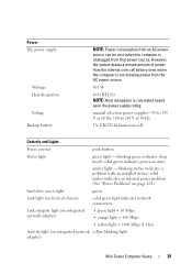
...the internal coin cell battery even when the computer is calculated based upon the power supply rating. solid green indicates power-on integrated network yellow blinking light adapter) Mini Tower Computer Views 29 manual selection power supplies-90 to 135 V at 60 Hz; 180 to 265 V at 50... Hz 3-V CR2032 lithium coin cell Controls and Lights Power control push button Power light green light - blinking amber indicates a problem with an ...
...the internal coin cell battery even when the computer is calculated based upon the power supply rating. solid green indicates power-on integrated network yellow blinking light adapter) Mini Tower Computer Views 29 manual selection power supplies-90 to 135 V at 60 Hz; 180 to 265 V at 50... Hz 3-V CR2032 lithium coin cell Controls and Lights Power control push button Power light green light - blinking amber indicates a problem with an ...

User's Guide
Page 41
... internal battery does draw a minute amount of power from the power supply even when the computer is not drawing power from the AC power source. 280 W 955 BTU/hr NOTE: Heat dissipation is calculated based upon the power supply rating. solid green indicates a power-on integrated network yellow blinking light adapter) Desktop... • yellow light = 1000 Mbps (1 Gbs) Activity light (on state. blinking amber indicates a problem with an installed device; manual selection power supplies - 90 to 135 V at 50/60 Hz; 180 to 265 V at 50/60 Hz 3-V CR2032 lithium coin cell Controls and Lights...
... internal battery does draw a minute amount of power from the power supply even when the computer is not drawing power from the AC power source. 280 W 955 BTU/hr NOTE: Heat dissipation is calculated based upon the power supply rating. solid green indicates a power-on integrated network yellow blinking light adapter) Desktop... • yellow light = 1000 Mbps (1 Gbs) Activity light (on state. blinking amber indicates a problem with an installed device; manual selection power supplies - 90 to 135 V at 50/60 Hz; 180 to 265 V at 50/60 Hz 3-V CR2032 lithium coin cell Controls and Lights...
User's Guide
Page 62
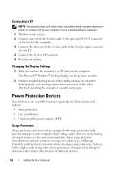
Changing the Display Settings 1 After you can occur during electrical storms or after power interruptions. Some surge protector manufacturers include warranty coverage for certain types of viewable work space. The Microsoft®...Enable extended desktop mode in the display settings. Power Protection Devices Several devices are available to protect against power fluctuations and failures: • Surge protectors • Line conditioners • Uninterruptible power supplies (UPS) Surge Protectors Surge protectors and power strips equipped with surge protection help prevent damage to...
Changing the Display Settings 1 After you can occur during electrical storms or after power interruptions. Some surge protector manufacturers include warranty coverage for certain types of viewable work space. The Microsoft®...Enable extended desktop mode in the display settings. Power Protection Devices Several devices are available to protect against power fluctuations and failures: • Surge protectors • Line conditioners • Uninterruptible power supplies (UPS) Surge Protectors Surge protectors and power strips equipped with surge protection help prevent damage to...

User's Guide
Page 63
... and interruptions. See the surge protector documentation for modem protection. A UPS protects against power fluctuations or power interruptions caused by Underwriters Laboratories (UL). NOTICE: Most surge protectors do not protect against power interruptions. Uninterruptible Power Supplies NOTICE: Loss of power while data is approved by nearby lightning strikes. When lightning occurs in data loss or file...
... and interruptions. See the surge protector documentation for modem protection. A UPS protects against power fluctuations or power interruptions caused by Underwriters Laboratories (UL). NOTICE: Most surge protectors do not protect against power interruptions. Uninterruptible Power Supplies NOTICE: Loss of power while data is approved by nearby lightning strikes. When lightning occurs in data loss or file...
User's Guide
Page 192
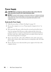
... 143. 2 Remove the computer cover (see "Removing the Computer Cover" on page 147). 3 Disconnect the DC power cables from the system board and drives. Replacing the Power Supply 1 Follow the procedures in the computer chassis as you remove them from being pinched or crimped. 4 Remove the ... cables from your body before you begin any of your computer, discharge static electricity from the securing clip on the computer chassis. Power Supply CAUTION: Before you touch any of the procedures in this section, follow the safety instructions located in the Product Information Guide. You...
... 143. 2 Remove the computer cover (see "Removing the Computer Cover" on page 147). 3 Disconnect the DC power cables from the system board and drives. Replacing the Power Supply 1 Follow the procedures in the computer chassis as you remove them from being pinched or crimped. 4 Remove the ... cables from your body before you begin any of your computer, discharge static electricity from the securing clip on the computer chassis. Power Supply CAUTION: Before you touch any of the procedures in this section, follow the safety instructions located in the Product Information Guide. You...

User's Guide
Page 193
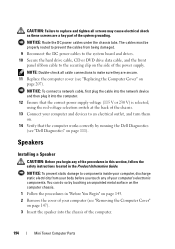
Mini Tower Computer Parts 193 1 2 3 4 5 1 release button 3 screws (4) 5 AC power connector 2 power supply 4 voltage selection switch (red) 6 Slide the power supply towards the front of the computer and lift it out. 7 Place and slide the replacement power supply toward the back of the computer. 8 Replace and tighten all screws that secure the power supply to the back of the computer chassis.
Mini Tower Computer Parts 193 1 2 3 4 5 1 release button 3 screws (4) 5 AC power connector 2 power supply 4 voltage selection switch (red) 6 Slide the power supply towards the front of the computer and lift it out. 7 Place and slide the replacement power supply toward the back of the computer. 8 Replace and tighten all screws that secure the power supply to the back of the computer chassis.
User's Guide
Page 194
...the cover of your computer (see "Removing the Computer Cover" on page 147). 3 Insert the speaker into the computer. 12 Ensure that the correct power supply voltage (115 V or 230 V) is selected, using the red voltage selection switch at the back of your computer and devices to an electrical outlet... are secure. 11 Replace the computer cover (see "Dell Diagnostics" on page 111). You can do so by running the Dell Diagnostics (see "Replacing the Computer Cover" on page 207). CAUTION: Failure to replace and tighten all cable connections to make sure they are a key part of the power supply.
...the cover of your computer (see "Removing the Computer Cover" on page 147). 3 Insert the speaker into the computer. 12 Ensure that the correct power supply voltage (115 V or 230 V) is selected, using the red voltage selection switch at the back of your computer and devices to an electrical outlet... are secure. 11 Replace the computer cover (see "Dell Diagnostics" on page 111). You can do so by running the Dell Diagnostics (see "Replacing the Computer Cover" on page 207). CAUTION: Failure to replace and tighten all cable connections to make sure they are a key part of the power supply.
User's Guide
Page 203
... sure that you can do so by moving fan blades, or other components may become very hot during normal operation. CAUTION: The heat sink assembly, power supply, and other unexpected injuries, always unplug your computer from your body before you touch any of the procedures in this section, follow the safety instructions...
... sure that you can do so by moving fan blades, or other components may become very hot during normal operation. CAUTION: The heat sink assembly, power supply, and other unexpected injuries, always unplug your computer from your body before you touch any of the procedures in this section, follow the safety instructions...
User's Guide
Page 205
...so that they have had sufficient time to cool before opening the cover. Mini Tower Computer Parts 205 CAUTION: The heat sink assembly, power supply, and other unexpected injuries, always unplug your computer and devices to dissipate any static electricity that could harm internal components. 1 Follow the... board is removed from the electrical outlet before you touch them on. 8 Verify that the computer works correctly by running the Dell Diagnostics (see "Dell Diagnostics" on page 207). Be sure that the memory modules can be installed in cards on the system board (see "Cards...
...so that they have had sufficient time to cool before opening the cover. Mini Tower Computer Parts 205 CAUTION: The heat sink assembly, power supply, and other unexpected injuries, always unplug your computer and devices to dissipate any static electricity that could harm internal components. 1 Follow the... board is removed from the electrical outlet before you touch them on. 8 Verify that the computer works correctly by running the Dell Diagnostics (see "Dell Diagnostics" on page 207). Be sure that the memory modules can be installed in cards on the system board (see "Cards...
User's Guide
Page 211
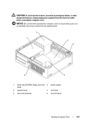
CAUTION: To avoid electrical shock, laceration by moving fan blades, or other unexpected injuries, always unplug your computer from the system board. 2 1 3 4 6 5 1 drives bay (CD/DVD, floppy, and hard 2 power supply drive) 3 system board 4 card slots 5 heat sink assembly 6 front I/O panel Desktop Computer Parts 211 NOTICE: Be careful when opening the computer cover to ensure that you do not accidentally disconnect cables from the electrical outlet before removing the computer cover.
CAUTION: To avoid electrical shock, laceration by moving fan blades, or other unexpected injuries, always unplug your computer from the system board. 2 1 3 4 6 5 1 drives bay (CD/DVD, floppy, and hard 2 power supply drive) 3 system board 4 card slots 5 heat sink assembly 6 front I/O panel Desktop Computer Parts 211 NOTICE: Be careful when opening the computer cover to ensure that you do not accidentally disconnect cables from the electrical outlet before removing the computer cover.
User's Guide
Page 242
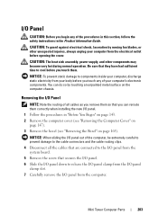
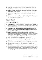
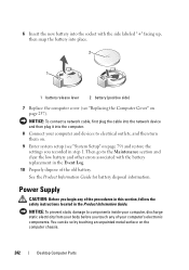
... damage to electrical outlets, and then turn them on. 9 Enter system setup (see "Replacing the Computer Cover" on the computer chassis. 242 Desktop Computer Parts Power Supply CAUTION: Before you touch any of the procedures in this section, follow the safety instructions located in step 1. See the Product Information Guide for battery...
... damage to electrical outlets, and then turn them on. 9 Enter system setup (see "Replacing the Computer Cover" on the computer chassis. 242 Desktop Computer Parts Power Supply CAUTION: Before you touch any of the procedures in this section, follow the safety instructions located in step 1. See the Product Information Guide for battery...


