User Manual
Page 2
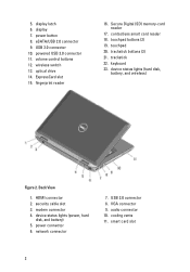
.... Secure Digital (SD) memory-card reader 17. keyboard 23. Back View 1. modem connector 4. power connector 6. smart card slot 2 display latch 6. power button 8. wireless switch 13. contactless smart card reader 18. device status lights (power, hard disk, and battery) 5. volume control buttons 12. fingerprint reader 16. trackstick 22. network connector 7. VGA connector 9. cooling vents 11. device...
.... Secure Digital (SD) memory-card reader 17. keyboard 23. Back View 1. modem connector 4. power connector 6. smart card slot 2 display latch 6. power button 8. wireless switch 13. contactless smart card reader 18. device status lights (power, hard disk, and battery) 5. volume control buttons 12. fingerprint reader 16. trackstick 22. network connector 7. VGA connector 9. cooling vents 11. device...
User Manual
Page 3
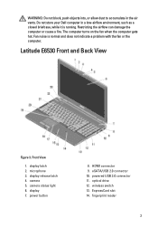
Do not store your Dell computer in the air vents. display release latch 4. display 7. ExpressCard slot 14. fingerprint reader 3 Restricting the airflow can damage the computer or cause a fire. display latch 2. camera 5. HDMI connector 9. powered USB 3.0 connector 11. optical drive 12. WARNING: Do not block, push ... computer turns on the fan when the computer gets hot. microphone 3. eSATA/USB 2.0 connector 10. Fan noise is running. Latitude E6530 Front and Back View Figure 3. camera status light 6. wireless switch 13. Front View 1. power button 8.
Do not store your Dell computer in the air vents. display release latch 4. display 7. ExpressCard slot 14. fingerprint reader 3 Restricting the airflow can damage the computer or cause a fire. display latch 2. camera 5. HDMI connector 9. powered USB 3.0 connector 11. optical drive 12. WARNING: Do not block, push ... computer turns on the fan when the computer gets hot. microphone 3. eSATA/USB 2.0 connector 10. Fan noise is running. Latitude E6530 Front and Back View Figure 3. camera status light 6. wireless switch 13. Front View 1. power button 8.
User Manual
Page 4
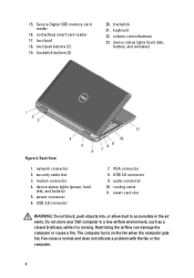
.... keyboard 22. volume control buttons 23. security cable slot 3. cooling vents 11. Back View 1. network connector 2. power connector 6. Do not store your Dell computer in the air vents. device status lights (power, hard disk, and battery) 5. device status lights (hard disk, battery, and wireless) Figure 4. USB 3.0 connector 9. Restricting the airflow can damage the computer...
.... keyboard 22. volume control buttons 23. security cable slot 3. cooling vents 11. Back View 1. network connector 2. power connector 6. Do not store your Dell computer in the air vents. device status lights (power, hard disk, and battery) 5. device status lights (hard disk, battery, and wireless) Figure 4. USB 3.0 connector 9. Restricting the airflow can damage the computer...
User Manual
Page 5
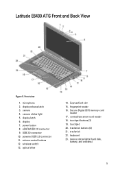
... 10. optical drive 14. trackstick buttons (3) 21. ExpressCard slot 15. contactless smart card reader 18. device status lights (hard disk, battery, and wireless) 5 touchpad 20. display latch 6. touchpad buttons (2) 19. camera 4. volume control buttons 12. power button 8. trackstick 22. wireless switch 13. fingerprint reader 16. keyboard 23. eSATA/USB 2.0 connector 9. Latitude E6430 ATG Front and Back View...
... 10. optical drive 14. trackstick buttons (3) 21. ExpressCard slot 15. contactless smart card reader 18. device status lights (hard disk, battery, and wireless) 5 touchpad 20. display latch 6. touchpad buttons (2) 19. camera 4. volume control buttons 12. power button 8. trackstick 22. wireless switch 13. fingerprint reader 16. keyboard 23. eSATA/USB 2.0 connector 9. Latitude E6430 ATG Front and Back View...
User Manual
Page 8
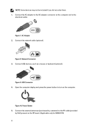
...the computer display and press the power button to turn on the RF board. (Applicable only for E6430 ATG) 8 AC Adapter 2. Figure 8. Connect USB devices, such as a mouse or keyboard (optional). Connect the network cable (optional). Figure 9. USB Connector 4. Power Button 5. Figure 10. Connect the ...external antennae (purchased by customer) to the electrical outlet. Network Connector 3. Connect the AC adapter to the AC adapter connector on the computer and to the RF cable (provided by Dell) present on the computer....
...the computer display and press the power button to turn on the RF board. (Applicable only for E6430 ATG) 8 AC Adapter 2. Figure 8. Connect USB devices, such as a mouse or keyboard (optional). Connect the network cable (optional). Figure 9. USB Connector 4. Power Button 5. Figure 10. Connect the ...external antennae (purchased by customer) to the electrical outlet. Network Connector 3. Connect the AC adapter to the AC adapter connector on the computer and to the RF cable (provided by Dell) present on the computer....
Owner's Manual
Page 8
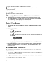
Remove the main battery. 8. Press the power button to your operating system, press and hold the power button for about 4 seconds to turn off your computer. The computer turns off when you service the computer. 7. After Working Inside Your Computer ... , then click Shut Down. - CAUTION: Before touching anything inside your computer from the appropriate slots. Do not use only the battery designed for other Dell computers. 1. Shut down on your computer. 1. Close the display and turn off after the operating system shutdown process is complete. 2. CAUTION: To guard...
Remove the main battery. 8. Press the power button to your operating system, press and hold the power button for about 4 seconds to turn off your computer. The computer turns off when you service the computer. 7. After Working Inside Your Computer ... , then click Shut Down. - CAUTION: Before touching anything inside your computer from the appropriate slots. Do not use only the battery designed for other Dell computers. 1. Shut down on your computer. 1. Close the display and turn off after the operating system shutdown process is complete. 2. CAUTION: To guard...
Intel Responsiveness Technologies Guide
Page 32
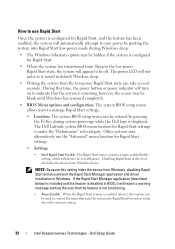
... the timer that the system is configured for Rapid Start. • When the system has transitioned from Windows device. Dell Setup Guide The Dell Latitude system BIOS menu location for Rapid Start settings is displayed. If the Rapid Start Manager application (described below) is installed.... • Timer Enable: When the Rapid Start feature is enabled (above), this time, the power button or power indicator will turn on to indicate that puts the system into Rapid Start low-power mode during system power-up, while the Dell logo is under the "Performance" sub-category.
... the timer that the system is configured for Rapid Start. • When the system has transitioned from Windows device. Dell Setup Guide The Dell Latitude system BIOS menu location for Rapid Start settings is displayed. If the Rapid Start Manager application (described below) is installed.... • Timer Enable: When the Rapid Start feature is enabled (above), this time, the power button or power indicator will turn on to indicate that puts the system into Rapid Start low-power mode during system power-up, while the Dell logo is under the "Performance" sub-category.


