User Manual
Page 2
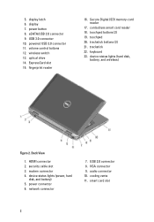
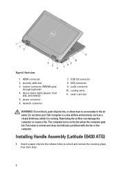
... 3.0 connector 11. ExpressCard slot 15. trackstick buttons (3) 21. Back View 1. modem connector 4. touchpad 20. volume control buttons 12. device status lights (power, hard disk, and battery) 5. VGA connector 9. USB 3.0 connector 10. fingerprint reader 16. wireless switch 13. trackstick 22. power connector 6. audio connector 10. contactless smart card reader 18. HDMI connector...
... 3.0 connector 11. ExpressCard slot 15. trackstick buttons (3) 21. Back View 1. modem connector 4. touchpad 20. volume control buttons 12. device status lights (power, hard disk, and battery) 5. VGA connector 9. USB 3.0 connector 10. fingerprint reader 16. wireless switch 13. trackstick 22. power connector 6. audio connector 10. contactless smart card reader 18. HDMI connector...
User Manual
Page 4
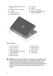
... power connector 6. cooling vents 11. touchpad 18. keyboard 22. USB 3.0 connector 9. Back View 1. device status lights (power, hard disk, and battery) 5. USB 2.0 connector 7. Fan noise is running. VGA connector 8. smart card slot WARNING: Do not block, push objects into, or allow dust to ...damage the computer or cause a fire. Secure Digital (SD) memory-card reader 16. device status lights (hard disk, battery, and wireless) Figure 4. 15. modem connector 4. contactless smart card reader 17. trackstick buttons (3) 20. security cable slot 3. Do not store ...
... power connector 6. cooling vents 11. touchpad 18. keyboard 22. USB 3.0 connector 9. Back View 1. device status lights (power, hard disk, and battery) 5. USB 2.0 connector 7. Fan noise is running. VGA connector 8. smart card slot WARNING: Do not block, push objects into, or allow dust to ...damage the computer or cause a fire. Secure Digital (SD) memory-card reader 16. device status lights (hard disk, battery, and wireless) Figure 4. 15. modem connector 4. contactless smart card reader 17. trackstick buttons (3) 20. security cable slot 3. Do not store ...
User Manual
Page 5
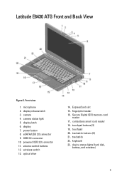
.... camera 4. powered USB 3.0 connector 11. trackstick buttons (3) 21. eSATA/USB 2.0 connector 9. volume control buttons 12. fingerprint reader 16. Latitude E6430 ATG Front and Back View Figure 5. touchpad buttons (2) 19. device status lights (hard disk, battery, and wireless) 5 display latch 6. microphone 2. USB 3.0 connector 10. wireless switch 13. Secure Digital (SD) memory-card reader 17...
.... camera 4. powered USB 3.0 connector 11. trackstick buttons (3) 21. eSATA/USB 2.0 connector 9. volume control buttons 12. fingerprint reader 16. Latitude E6430 ATG Front and Back View Figure 5. touchpad buttons (2) 19. device status lights (hard disk, battery, and wireless) 5 display latch 6. microphone 2. USB 3.0 connector 10. wireless switch 13. Secure Digital (SD) memory-card reader 17...
User Manual
Page 6
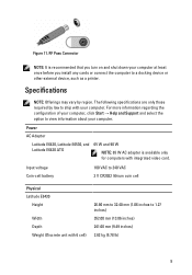
... battery) 5. Do not store your Dell computer in the air vents. The computer turns on the fan when the computer gets hot. cooling vents 11. Insert a paper clip into , or allow dust to unlock and remove the covering plugs from their slots. 6 power connector 6. network connector 7. USB 2.0 connector 8. Installing Handle Assembly (Latitude E6430 ATG...
... battery) 5. Do not store your Dell computer in the air vents. The computer turns on the fan when the computer gets hot. cooling vents 11. Insert a paper clip into , or allow dust to unlock and remove the covering plugs from their slots. 6 power connector 6. network connector 7. USB 2.0 connector 8. Installing Handle Assembly (Latitude E6430 ATG...
User Manual
Page 9
... to ship with 6 cell) 26.90 mm to 32.40 mm (1.06 inches to view information about your computer. Power AC Adapter Latitude E6430, Latitude E6530, and Latitude E6430 ATG 65 W and 90 W NOTE: 65 W AC adapter is recommended that you turn on and shut down your computer at least ...once before you install any cards or connect the computer to 240 VAC 3 V CR2032 lithium coin cell Physical Latitude E6430 Height Width Depth Weight (Discrete unit with your computer. Input voltage Coin-cell battery 100 VAC to a docking device or other external device, such as a printer.
... to ship with 6 cell) 26.90 mm to 32.40 mm (1.06 inches to view information about your computer. Power AC Adapter Latitude E6430, Latitude E6530, and Latitude E6430 ATG 65 W and 90 W NOTE: 65 W AC adapter is recommended that you turn on and shut down your computer at least ...once before you install any cards or connect the computer to 240 VAC 3 V CR2032 lithium coin cell Physical Latitude E6430 Height Width Depth Weight (Discrete unit with your computer. Input voltage Coin-cell battery 100 VAC to a docking device or other external device, such as a printer.
Owner's Manual
Page 3
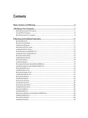
... Removing the Secure Digital (SD) Card...12 Installing the Secure Digital (SD) Card...13 Removing the ExpressCard...13 Installing the ExpressCard...13 Removing the Battery...14 Installing the Battery...14 Removing the Subscriber Identity Module (SIM) Card 14 Installing the Subscriber Identity Module (SIM) Card 14 Removing the Base Cover...15 Installing...
... Removing the Secure Digital (SD) Card...12 Installing the Secure Digital (SD) Card...13 Removing the ExpressCard...13 Installing the ExpressCard...13 Removing the Battery...14 Installing the Battery...14 Removing the Subscriber Identity Module (SIM) Card 14 Installing the Subscriber Identity Module (SIM) Card 14 Removing the Base Cover...15 Installing...

Owner's Manual
Page 4
Removing the Processor...26 Installing the Processor...26 Removing the Bluetooth Card...26 Installing the Bluetooth Card...28 Removing the Coin-Cell Battery...28 Installing the Coin-Cell Battery...28 Removing the ExpressCard Cage...29 Installing the ExpressCard Cage...29 Removing the Media Board...30 Installing the Media Board...31 Removing the Power...
Removing the Processor...26 Installing the Processor...26 Removing the Bluetooth Card...26 Installing the Bluetooth Card...28 Removing the Coin-Cell Battery...28 Installing the Coin-Cell Battery...28 Removing the ExpressCard Cage...29 Installing the ExpressCard Cage...29 Removing the Media Board...30 Installing the Media Board...31 Removing the Power...
Owner's Manual
Page 5
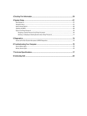
3 Docking Port Information...59 4 System Setup...61 Boot Sequence...61 Navigation Keys...61 System Setup Options...62 Updating the BIOS ...69 System and Setup Password...70 Assigning a System Password and Setup Password 70 Deleting or Changing an Existing System and/or Setup Password 71 5 Diagnostics...73 Enhanced Pre-Boot System Assessment (ePSA) Diagnostics 73 6 Troubleshooting Your Computer 75 Device Status Lights...75 Battery Status Lights...76 7 Technical Specifications...77 8 Contacting Dell ...83
3 Docking Port Information...59 4 System Setup...61 Boot Sequence...61 Navigation Keys...61 System Setup Options...62 Updating the BIOS ...69 System and Setup Password...70 Assigning a System Password and Setup Password 70 Deleting or Changing an Existing System and/or Setup Password 71 5 Diagnostics...73 Enhanced Pre-Boot System Assessment (ePSA) Diagnostics 73 6 Troubleshooting Your Computer 75 Device Status Lights...75 Battery Status Lights...76 7 Technical Specifications...77 8 Contacting Dell ...83
Owner's Manual
Page 7
...Computer. • You have connectors with the product. You should only perform troubleshooting and simple repairs as the optional Media Base or Battery Slice, undock it. Also, before you disconnect a cable, pull on its connector or on its pull-tab, not on the cable... service and support team. Disconnect all attached devices from the computer. 5. Disconnect your computer (see the Regulatory Compliance Homepage at www.dell.com/ regulatory_compliance CAUTION: Many repairs may appear differently than shown in on the locking tabs before you disconnect the cable. Hold a ...
...Computer. • You have connectors with the product. You should only perform troubleshooting and simple repairs as the optional Media Base or Battery Slice, undock it. Also, before you disconnect a cable, pull on its connector or on its pull-tab, not on the cable... service and support team. Disconnect all attached devices from the computer. 5. Disconnect your computer (see the Regulatory Compliance Homepage at www.dell.com/ regulatory_compliance CAUTION: Many repairs may appear differently than shown in on the locking tabs before you disconnect the cable. Hold a ...
Owner's Manual
Page 8
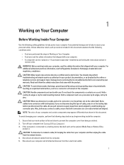
...1. Turn the computer top-side up. 9. If your computer and attached devices did not automatically turn them off. Remove the main battery. 8. Ensure that the computer and all open files and exit all attached devices are turned off after the operating system shutdown process is... To avoid damage to your computer from the appropriate slots. Remove any telephone or network cables to the computer, use batteries designed for this particular Dell computer. While you service the computer. 7. Connect any installed ExpressCards or Smart Cards from the electrical outlet before you ...
...1. Turn the computer top-side up. 9. If your computer and attached devices did not automatically turn them off. Remove the main battery. 8. Ensure that the computer and all open files and exit all attached devices are turned off after the operating system shutdown process is... To avoid damage to your computer from the appropriate slots. Remove any telephone or network cables to the computer, use batteries designed for this particular Dell computer. While you service the computer. 7. Connect any installed ExpressCards or Smart Cards from the electrical outlet before you ...

Owner's Manual
Page 9
Connect your computer. 9 CAUTION: To connect a network cable, first plug the cable into the network device and then plug it into the computer. 3. Replace the battery. 4. Turn on your computer and all attached devices to their electrical outlets. 5.
Connect your computer. 9 CAUTION: To connect a network cable, first plug the cable into the network device and then plug it into the computer. 3. Replace the battery. 4. Turn on your computer and all attached devices to their electrical outlets. 5.
Owner's Manual
Page 14
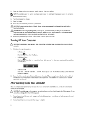
... the Subscriber Identity Module (SIM) Card 1. Follow the procedures in Before Working Inside Your Computer. 2. Removing the Battery 1. Installing the Battery 1. Slide the battery into place. 2. Slide the SIM card into its slot until it clicks into its slot. 2. Remove the SIM card from the computer. Follow the procedures ...
... the Subscriber Identity Module (SIM) Card 1. Follow the procedures in Before Working Inside Your Computer. 2. Removing the Battery 1. Installing the Battery 1. Slide the battery into place. 2. Slide the SIM card into its slot until it clicks into its slot. 2. Remove the SIM card from the computer. Follow the procedures ...
Owner's Manual
Page 15
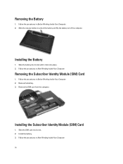
... procedures in After Working Inside Your Computer. Tighten the screws to secure the base cover to release it from the computer. 15 Install the battery. 4. Remove the battery. 3. Follow the procedures in Before Working Inside Your Computer. 2. Removing the Base Cover 1. Lift the base cover to remove it from the computer. Using...
... procedures in After Working Inside Your Computer. Tighten the screws to secure the base cover to release it from the computer. 15 Install the battery. 4. Remove the battery. 3. Follow the procedures in Before Working Inside Your Computer. 2. Removing the Base Cover 1. Lift the base cover to remove it from the computer. Using...

Owner's Manual
Page 16
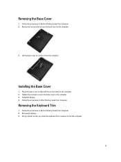
Lift up to computer. 16 Installing the Keyboard Trim 1. Remove the screws that secure the keyboard to remove the keyboard trim from the unit. Remove: a) battery b) keyboard trim 3. Follow the procedures in Before Working Inside Your Computer. 2. Pry the keyboard trim along the sides of the keyboard trim until it clicks in place. 3. Install the battery. 4. Removing the Keyboard 1. Align the keyboard trim to its slot. 2. 4. Press along the sides and bottom. 5. Follow the procedures in After Working Inside Your Computer.
Lift up to computer. 16 Installing the Keyboard Trim 1. Remove the screws that secure the keyboard to remove the keyboard trim from the unit. Remove: a) battery b) keyboard trim 3. Follow the procedures in Before Working Inside Your Computer. 2. Pry the keyboard trim along the sides of the keyboard trim until it clicks in place. 3. Install the battery. 4. Removing the Keyboard 1. Align the keyboard trim to its slot. 2. 4. Press along the sides and bottom. 5. Follow the procedures in After Working Inside Your Computer.
Owner's Manual
Page 18
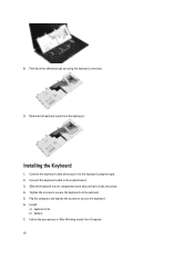
... the palmrest. 5. Follow the procedures in After Working Inside Your Computer. 18 Installing the Keyboard 1. Remove the keyboard cable from the keyboard. Install: a) keyboard trim b) battery 7. 8. Peel back the adhesive tape securing the keyboard connector. 9. Tighten the screws to the keyboard using the tape. 2.
... the palmrest. 5. Follow the procedures in After Working Inside Your Computer. 18 Installing the Keyboard 1. Remove the keyboard cable from the keyboard. Install: a) keyboard trim b) battery 7. 8. Peel back the adhesive tape securing the keyboard connector. 9. Tighten the screws to the keyboard using the tape. 2.
Owner's Manual
Page 19
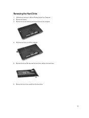
Slide the hard drive out of the computer. 5. Follow the procedures in Before Working Inside Your Computer. 2. Remove the screws that secures the hard-drive caddy to the computer. 4. Remove the screw that secure the hard drive to the hard drive. 6. Remove the battery. 3. Remove the hard-drive caddy from the hard drive. 19 Removing the Hard Drive 1.
Slide the hard drive out of the computer. 5. Follow the procedures in Before Working Inside Your Computer. 2. Remove the screws that secures the hard-drive caddy to the computer. 4. Remove the screw that secure the hard drive to the hard drive. 6. Remove the battery. 3. Remove the hard-drive caddy from the hard drive. 19 Removing the Hard Drive 1.
Owner's Manual
Page 20
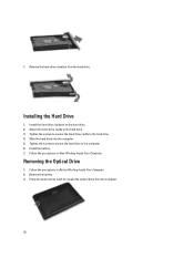
... hard-drive caddy to the hard drive. 4. Slide the hard drive into the computer. 5. Follow the procedures in After Working Inside Your Computer. Install the battery. 7. Tighten the screws to secure the hard-drive caddy to the hard drive. 3. Tighten the screws to secure the hard drive to release the optical...-drive latch to the computer. 6. Remove the hard-drive isolation from the computer. 20 Install the hard-drive isolation on the hard drive. 2. Remove the battery. 3. Follow the procedures in Before Working Inside Your Computer. 2. 7.
... hard-drive caddy to the hard drive. 4. Slide the hard drive into the computer. 5. Follow the procedures in After Working Inside Your Computer. Install the battery. 7. Tighten the screws to secure the hard-drive caddy to the hard drive. 3. Tighten the screws to secure the hard drive to release the optical...-drive latch to the computer. 6. Remove the hard-drive isolation from the computer. 20 Install the hard-drive isolation on the hard drive. 2. Remove the battery. 3. Follow the procedures in Before Working Inside Your Computer. 2. 7.

Owner's Manual
Page 22
... secure the optical-drive latch bracket to secure the optical drive latch. 6. Removing the Memory 1. Tighten the screw to the optical drive assembly. 4. Install the battery. 9. Remove: a) battery b) base cover 3. Installing the Optical Drive 1. Secure the optical-drive door to secure the optical drive. 8. Follow the procedures in After Working Inside Your...
... secure the optical-drive latch bracket to secure the optical drive latch. 6. Removing the Memory 1. Tighten the screw to the optical drive assembly. 4. Install the battery. 9. Remove: a) battery b) base cover 3. Installing the Optical Drive 1. Secure the optical-drive door to secure the optical drive. 8. Follow the procedures in After Working Inside Your...
Owner's Manual
Page 23
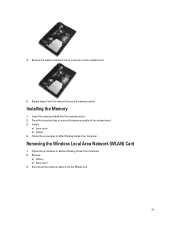
Insert the memory module into the memory socket. 2. Removing the Wireless Local Area Network (WLAN) Card 1. 4. Remove: a) battery b) base cover 3. Install: a) base cover b) battery 4. Installing the Memory 1. Follow the procedures in Before Working Inside Your Computer. 2. Repeat steps 2 and 3 to the system board. 3. Remove the memory module from the ...
Insert the memory module into the memory socket. 2. Removing the Wireless Local Area Network (WLAN) Card 1. 4. Remove: a) battery b) base cover 3. Install: a) base cover b) battery 4. Installing the Memory 1. Follow the procedures in Before Working Inside Your Computer. 2. Repeat steps 2 and 3 to the system board. 3. Remove the memory module from the ...
Owner's Manual
Page 24
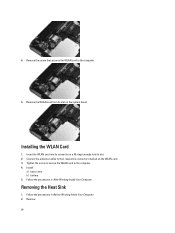
... Before Working Inside Your Computer. 2. Installing the WLAN Card 1. Follow the procedures in After Working Inside Your Computer. Removing the Heat Sink 1. 4. Install: a) base cover b) battery 5. Tighten the screw to secure the WLAN card to the computer. 5. Remove the screw that secures the WLAN card to the computer. 4. Remove: 24 Connect...
... Before Working Inside Your Computer. 2. Installing the WLAN Card 1. Follow the procedures in After Working Inside Your Computer. Removing the Heat Sink 1. 4. Install: a) base cover b) battery 5. Tighten the screw to secure the WLAN card to the computer. 5. Remove the screw that secures the WLAN card to the computer. 4. Remove: 24 Connect...


