User Manual
Page 2
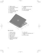
powered USB 3.0 connector 9. device status lights Figure 2. network connector 2. cooling vents 9. Secure Digital (SD) memory-card reader 10. touchpad 14. volume control buttons (3) 17. touchpad buttons (2) 13. contactless smart-card reader (optional) 15. keyboard 16. power connector 5. eSATA/USB 2.0 connector 7. audio/microphone combo connector 8. smart card reader 2 ExpressCard slot 11. device status lights 3. USB 3.0 connector 8. fingerprint reader (optional) 12. 7. security cable slot 4. VGA connector 6. wireless switch 10. Back View 1.
powered USB 3.0 connector 9. device status lights Figure 2. network connector 2. cooling vents 9. Secure Digital (SD) memory-card reader 10. touchpad 14. volume control buttons (3) 17. touchpad buttons (2) 13. contactless smart-card reader (optional) 15. keyboard 16. power connector 5. eSATA/USB 2.0 connector 7. audio/microphone combo connector 8. smart card reader 2 ExpressCard slot 11. device status lights 3. USB 3.0 connector 8. fingerprint reader (optional) 12. 7. security cable slot 4. VGA connector 6. wireless switch 10. Back View 1.
User Manual
Page 3
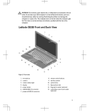
...is running. camera 3. eSATA/USB 2.0 connector 7. ExpressCard slot 12. Latitude E6330 Front and Back View Figure 3. fingerprint reader (optional) 13. contactless smart card reader (optional) 3 volume control buttons 9. microphone 2. power button 6.... WARNING: Do not block, push objects into, or allow dust to accumulate in a low-airflow environment, such as a closed briefcase, while it is normal and does not indicate a problem with the fan or the computer. Do not store your Dell...
...is running. camera 3. eSATA/USB 2.0 connector 7. ExpressCard slot 12. Latitude E6330 Front and Back View Figure 3. fingerprint reader (optional) 13. contactless smart card reader (optional) 3 volume control buttons 9. microphone 2. power button 6.... WARNING: Do not block, push objects into, or allow dust to accumulate in a low-airflow environment, such as a closed briefcase, while it is normal and does not indicate a problem with the fan or the computer. Do not store your Dell...
User Manual
Page 4
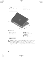
keyboard 20. security cable slot 2. USB 3.0 connector 6. Fan noise is running. power connector 7. VGA connector 8. smart card slot (optional) WARNING: Do not block, push objects into, or allow dust to accumulate in a low-airflow environment, such as a closed briefcase, while... it is normal and does not indicate a problem with the fan or the computer. 4 Do not store your Dell computer in the air vents. mini HDMI connector 4. device status lights 5. trackstick 19. audio/microphone combo connector 9. The computer turns on the fan when...
keyboard 20. security cable slot 2. USB 3.0 connector 6. Fan noise is running. power connector 7. VGA connector 8. smart card slot (optional) WARNING: Do not block, push objects into, or allow dust to accumulate in a low-airflow environment, such as a closed briefcase, while... it is normal and does not indicate a problem with the fan or the computer. 4 Do not store your Dell computer in the air vents. mini HDMI connector 4. device status lights 5. trackstick 19. audio/microphone combo connector 9. The computer turns on the fan when...
Owner's Manual
Page 4
... the ExpressCard Cage...36 Installing the ExpressCard Cage...37 Removing the WiFi-Switch Board ...37 Installing the WiFi-Switch Board...38 Removing the Smart Card Cage...39 Installing the Smart Card Cage...40 Removing the Display Bezel...40 Installing the Display Bezel...41 Removing the Display Panel...41 Installing the Display Panel...42 Removing...
... the ExpressCard Cage...36 Installing the ExpressCard Cage...37 Removing the WiFi-Switch Board ...37 Installing the WiFi-Switch Board...38 Removing the Smart Card Cage...39 Installing the Smart Card Cage...40 Removing the Display Bezel...40 Installing the Display Bezel...41 Removing the Display Panel...41 Installing the Display Panel...42 Removing...
Owner's Manual
Page 8
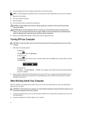
...after the operating system shutdown process is complete. 2. After Working Inside Your Computer After you complete any installed ExpressCards or Smart Cards from the electrical outlet before turning on a flat work , periodically touch an unpainted metal surface to the computer, use batteries... designed for this particular Dell computer. Do not use only the battery designed for other Dell computers. 1. Press the power button to turn the computer upside-down the operating system: - While...
...after the operating system shutdown process is complete. 2. After Working Inside Your Computer After you complete any installed ExpressCards or Smart Cards from the electrical outlet before turning on a flat work , periodically touch an unpainted metal surface to the computer, use batteries... designed for this particular Dell computer. Do not use only the battery designed for other Dell computers. 1. Press the power button to turn the computer upside-down the operating system: - While...
Owner's Manual
Page 19
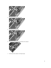
4. Disconnect the touchpad cable. 6. Flip the base of the computer to the computer. 7. Remove the screws that secures the palmrest to a 45-degree angle. 19 Disconnect the Smart Card reader cable. 5.
4. Disconnect the touchpad cable. 6. Flip the base of the computer to the computer. 7. Remove the screws that secures the palmrest to a 45-degree angle. 19 Disconnect the Smart Card reader cable. 5.
Owner's Manual
Page 20
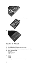
Press downward on the palmrest from the base of the palmrest until it snaps in After Working Inside Your Computer. 20 Connect the following cables: a) touchpad b) Smart Card reader c) SD card reader 5. Press along the sides of the computer. 9. Follow the procedures in place. 3. Remove the palmrest. Align the palmrest to its slot. 2. Flip the computer and tighten the screws that secures the palmrest in place. 4. Install the: a) cover b) battery 6. Installing the Palmrest 1. 8.
Press downward on the palmrest from the base of the palmrest until it snaps in After Working Inside Your Computer. 20 Connect the following cables: a) touchpad b) Smart Card reader c) SD card reader 5. Press along the sides of the computer. 9. Follow the procedures in place. 3. Remove the palmrest. Align the palmrest to its slot. 2. Flip the computer and tighten the screws that secures the palmrest in place. 4. Install the: a) cover b) battery 6. Installing the Palmrest 1. 8.
Owner's Manual
Page 39
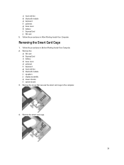
Follow the procedures in Before Working Inside Your Computer. 2. Remove the smart card cage. 39 Remove the: a) SD card b) ExpressCard c) battery d) base cover e) palmrest f) keyboard g) heat-sink fan h) bluetooth module i) speakers j) display assembly k) lower chassis l) system board 3. Remove the screw that secures the smart card cage to the computer. 4. c) heat-sink fan d) bluetooth module e) keyboard f) palmrest g) base cover h) battery i) ExpressCard j) SD card 5. Follow the procedures in After Working Inside Your Computer. Removing the Smart Card Cage 1.
Follow the procedures in Before Working Inside Your Computer. 2. Remove the smart card cage. 39 Remove the: a) SD card b) ExpressCard c) battery d) base cover e) palmrest f) keyboard g) heat-sink fan h) bluetooth module i) speakers j) display assembly k) lower chassis l) system board 3. Remove the screw that secures the smart card cage to the computer. 4. c) heat-sink fan d) bluetooth module e) keyboard f) palmrest g) base cover h) battery i) ExpressCard j) SD card 5. Follow the procedures in After Working Inside Your Computer. Removing the Smart Card Cage 1.
Owner's Manual
Page 40
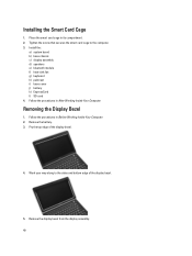
... assembly d) speakers e) bluetooth module f) heat-sink fan g) keyboard h) palmrest i) base cover j) battery k) ExpressCard l) SD card 4. Follow the procedures in its compartment. 2. Place the smart card cage in Before Working Inside Your Computer. 2. Pry the top edge of the display bezel. 5. Follow the procedures in After .... 3. Remove the display bezel from the display assembly. 40 Remove the battery. 3. Installing the Smart Card Cage 1. Tighten the screw that secures the smart card cage to the sides and bottom edge of the display bezel. 4. Removing the Display Bezel 1.
... assembly d) speakers e) bluetooth module f) heat-sink fan g) keyboard h) palmrest i) base cover j) battery k) ExpressCard l) SD card 4. Follow the procedures in its compartment. 2. Place the smart card cage in Before Working Inside Your Computer. 2. Pry the top edge of the display bezel. 5. Follow the procedures in After .... 3. Remove the display bezel from the display assembly. 40 Remove the battery. 3. Installing the Smart Card Cage 1. Tighten the screw that secures the smart card cage to the sides and bottom edge of the display bezel. 4. Removing the Display Bezel 1.
Owner's Manual
Page 54
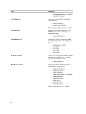
... to define the USB configuration. Option USB Configuration USB PowerShare Keyboard Illumination Stealth Mode Control Miscellaneous Devices 54 Description • Enable SMART Reporting - The options are: • Enable Internal Modem • Enable Microphone • Enable eSATA Ports • Enable ...Hard Drive Free Fall Protection • Enable Module Bay • Enable ExpressCard • Enable Camera • Enable Media Card • Disable Media Card Default Setting: All devices are enabled. The options are: • Enable Boot Support • Enable External USB Port Default...
... to define the USB configuration. Option USB Configuration USB PowerShare Keyboard Illumination Stealth Mode Control Miscellaneous Devices 54 Description • Enable SMART Reporting - The options are: • Enable Internal Modem • Enable Microphone • Enable eSATA Ports • Enable ...Hard Drive Free Fall Protection • Enable Module Bay • Enable ExpressCard • Enable Camera • Enable Media Card • Disable Media Card Default Setting: All devices are enabled. The options are: • Enable Boot Support • Enable External USB Port Default...
Owner's Manual
Page 68
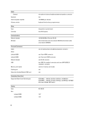
... Volume controls Video Type Controller Communications Network adapter Wireless Ports and Connectors Audio Video: Latitude E6230 Latitude E6330 Network adapter USB Memory card reader Docking port Subscriber Identity Module (SIM) card Contactless Smart Card Supported Smart Cards/Technologies Display Type Size Latitude E6230 Latitude E6330 microphone-in -1 memory card reader one one eSATA/USB 2.0 compliant- connector one 8-in /stereo headphones/external speakers connector...
... Volume controls Video Type Controller Communications Network adapter Wireless Ports and Connectors Audio Video: Latitude E6230 Latitude E6330 Network adapter USB Memory card reader Docking port Subscriber Identity Module (SIM) card Contactless Smart Card Supported Smart Cards/Technologies Display Type Size Latitude E6230 Latitude E6330 microphone-in -1 memory card reader one one eSATA/USB 2.0 compliant- connector one 8-in /stereo headphones/external speakers connector...


