
Service Manual
Page 11
... the component screws. When you are removing and replacing components, photocopy the Table 1 placement mat as a tool to your system) Thermal Cooling Assembly and Exhaust Fan: M2.5 x 4 (2 each) 4 Dell Latitude CPt V/CPt S Series and CPx H/CPx J Series Service Manual
... the component screws. When you are removing and replacing components, photocopy the Table 1 placement mat as a tool to your system) Thermal Cooling Assembly and Exhaust Fan: M2.5 x 4 (2 each) 4 Dell Latitude CPt V/CPt S Series and CPx H/CPx J Series Service Manual

Service Manual
Page 16
..., BIOS, FLASH, UPG, F3 Diagnostic diskette KIT, DSK, DIAG, F3, WW System board assembly ASSY, PWA, ENGINE Main system board PWA, PLN, 0M, NB Exhaust fan and FAN, 25X25X10 cable Thermal cooling SVC, SUBASSY, HTSNK, CPU, HYB assembly Microprocessor, SVC, PRM, PCA 12 Service Kit Microprocessor shield/ SCR, M2X3, PHH, LP, ZPS... Kit, latch, slider, Button Foot, Rubber, Black (4 each) Foot, Rubber, Strike Zone, Black LTCH, BTN, Module Foot, Rbr, Blk Foot, Rbr, Strike Zone, Blk support.dell.com Dell Latitude CPt V/CPt S Series and CPx H/CPx J Series Service Manual 9
..., BIOS, FLASH, UPG, F3 Diagnostic diskette KIT, DSK, DIAG, F3, WW System board assembly ASSY, PWA, ENGINE Main system board PWA, PLN, 0M, NB Exhaust fan and FAN, 25X25X10 cable Thermal cooling SVC, SUBASSY, HTSNK, CPU, HYB assembly Microprocessor, SVC, PRM, PCA 12 Service Kit Microprocessor shield/ SCR, M2X3, PHH, LP, ZPS... Kit, latch, slider, Button Foot, Rubber, Black (4 each) Foot, Rubber, Strike Zone, Black LTCH, BTN, Module Foot, Rbr, Blk Foot, Rbr, Strike Zone, Blk support.dell.com Dell Latitude CPt V/CPt S Series and CPx H/CPx J Series Service Manual 9
Service Manual
Page 43
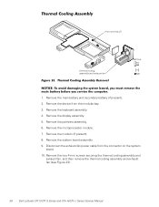
... assembly. 9. Remove the keyboard assembly. 4. Remove the two 4-mm screws securing the thermal cooling assembly and exhaust fan, and then remove the thermal cooling assembly and exhaust fan (see Figure 23). 36 Dell Latitude CPt V/CPt S Series and CPx H/CPx J Series Service Manual Remove the palmrest assembly. 6. Remove the main battery and secondary battery (if present). 2.
... assembly. 9. Remove the keyboard assembly. 4. Remove the two 4-mm screws securing the thermal cooling assembly and exhaust fan, and then remove the thermal cooling assembly and exhaust fan (see Figure 23). 36 Dell Latitude CPt V/CPt S Series and CPx H/CPx J Series Service Manual Remove the palmrest assembly. 6. Remove the main battery and secondary battery (if present). 2.
System Information Guide (multilanguage: English, Japanese, Chinese-Traditional, Chinese-Simplified, Korean, Thai)
Page 10
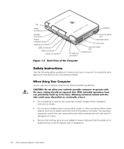
(Rev. 11/3/98) FILE LOCATION: \\Pd-xuzhan\d\FrameMaker\Dell\sndmm003\en\999CCA00en.fm fan video connector parallel connector status indicator panel docking connector USB connector PS/2 connector serial connector speaker security cable slot hard-disk drive PC ... closely. • Do not carry a battery pack in damage from potential damage and to help ensure your own personal safety. Preliminary 1/25/00 1-6 Dell Latitude System Information The resulting excessive current flow can be tripped over or stepped on your pocket, purse, or other container where metal objects (such as...
(Rev. 11/3/98) FILE LOCATION: \\Pd-xuzhan\d\FrameMaker\Dell\sndmm003\en\999CCA00en.fm fan video connector parallel connector status indicator panel docking connector USB connector PS/2 connector serial connector speaker security cable slot hard-disk drive PC ... closely. • Do not carry a battery pack in damage from potential damage and to help ensure your own personal safety. Preliminary 1/25/00 1-6 Dell Latitude System Information The resulting excessive current flow can be tripped over or stepped on your pocket, purse, or other container where metal objects (such as...


