Service Manual
Page 4
...-ROM Drive, DVD-ROM Drive, CD-RW Drive, SuperDisk LS-120 Drive, Battery, or Travel Module) . . . . 12 Memory Module Cover 12 Removing the Memory Module Cover 12 Memory Modules 13 Removing the Memory Modules 13 Replacing the Memory Modules 13 Keyboard Assembly 14 Removing the Keyboard Assembly 14 Replacing the Keyboard Assembly 16 Microprocessor Module...
...-ROM Drive, DVD-ROM Drive, CD-RW Drive, SuperDisk LS-120 Drive, Battery, or Travel Module) . . . . 12 Memory Module Cover 12 Removing the Memory Module Cover 12 Memory Modules 13 Removing the Memory Modules 13 Replacing the Memory Modules 13 Keyboard Assembly 14 Removing the Keyboard Assembly 14 Replacing the Keyboard Assembly 16 Microprocessor Module...
Service Manual
Page 5
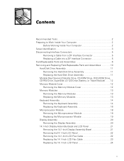
... Battery Removal 3 Screw Identification 3 Disconnecting a Cable from an Interface Connector 5 Exploded View-Computer 10 Hard-Disk Drive Assembly Removal 11 Modular Bay Device Removal 12 Memory Module Removal 13 Removing the Keyboard Assembly Screws 14 Keyboard Assembly Removal 15 Keyboard and Track Stick Cables and Connectors 16 Microprocessor Module Removal 18...
... Battery Removal 3 Screw Identification 3 Disconnecting a Cable from an Interface Connector 5 Exploded View-Computer 10 Hard-Disk Drive Assembly Removal 11 Modular Bay Device Removal 12 Memory Module Removal 13 Removing the Keyboard Assembly Screws 14 Keyboard Assembly Removal 15 Keyboard and Track Stick Cables and Connectors 16 Microprocessor Module Removal 18...

Service Manual
Page 15
... Customer kit, memory CUS, 32MB, DIMM, SDRAM 8 module, 32-MB Customer kit, memory module, 64-MB CUS, 64MB, DIMM, SDRAM Customer kit, memory module, 128-MB CUS, 128MB, DIMM, SDRAM Customer kit, memory module, 192-MB CUS, 192MB, DIMM, SDRAM Customer kit, memory module, 256-MB CUS, 256MB, DIMM, SDRAM 8 Dell Latitude CPt V/CPt S Series and CPx H/CPx J Series...
... Customer kit, memory CUS, 32MB, DIMM, SDRAM 8 module, 32-MB Customer kit, memory module, 64-MB CUS, 64MB, DIMM, SDRAM Customer kit, memory module, 128-MB CUS, 128MB, DIMM, SDRAM Customer kit, memory module, 192-MB CUS, 192MB, DIMM, SDRAM Customer kit, memory module, 256-MB CUS, 256MB, DIMM, SDRAM 8 Dell Latitude CPt V/CPt S Series and CPx H/CPx J Series...

Service Manual
Page 16
Memory door assembly DOOR, MEM, MET, NB System board assembly, SVCKIT, MB ASSY, PWA, ENGINE 22 service kit Service tag installation diskette DSK, BIOS, FLDSVC, F3, ... Kit, latch, slider, Button Foot, Rubber, Black (4 each) Foot, Rubber, Strike Zone, Black LTCH, BTN, Module Foot, Rbr, Blk Foot, Rbr, Strike Zone, Blk support.dell.com Dell Latitude CPt V/CPt S Series and CPx H/CPx J Series Service Manual 9
Memory door assembly DOOR, MEM, MET, NB System board assembly, SVCKIT, MB ASSY, PWA, ENGINE 22 service kit Service tag installation diskette DSK, BIOS, FLDSVC, F3, ... Kit, latch, slider, Button Foot, Rubber, Black (4 each) Foot, Rubber, Strike Zone, Black LTCH, BTN, Module Foot, Rbr, Blk Foot, Rbr, Strike Zone, Blk support.dell.com Dell Latitude CPt V/CPt S Series and CPx H/CPx J Series Service Manual 9

Service Manual
Page 19
... device out of the modular bay with the other hand (see Figure 7). 1. Release the memory module cover. Insert a flat-blade screwdriver under the indentation in the bottom case assembly and lift the cover. 12 Dell Latitude CPt V/CPt S Series and CPx H/CPx J Series Service Manual latch lock 1. Remove the main battery and secondary battery (if...
... device out of the modular bay with the other hand (see Figure 7). 1. Release the memory module cover. Insert a flat-blade screwdriver under the indentation in the bottom case assembly and lift the cover. 12 Dell Latitude CPt V/CPt S Series and CPx H/CPx J Series Service Manual latch lock 1. Remove the main battery and secondary battery (if...

Service Manual
Page 20
... fit into their sockets, in the socket. NOTES: 192-MB memory modules are keyed, or designed to disengage from its socket. 1. support.dell.com Dell Latitude CPt V/CPt S Series and CPx H/CPx J Series Service Manual 13 The slots on the system board are not interchangeable. Remove the memory module cover. 3. Remove the main battery and secondary battery...
... fit into their sockets, in the socket. NOTES: 192-MB memory modules are keyed, or designed to disengage from its socket. 1. support.dell.com Dell Latitude CPt V/CPt S Series and CPx H/CPx J Series Service Manual 13 The slots on the system board are not interchangeable. Remove the memory module cover. 3. Remove the main battery and secondary battery...

Service Manual
Page 21
... work surface. 10-mm screws (7) M2.5x10 14 Dell Latitude CPt V/CPt S Series and CPx H/CPx J Series Service Manual Align the memory module's edge connector with the slot in the center of the memory module snaps into the tabs, remove the memory module and reinstall it clicks into the memory module socket. 3. Close the display assembly, and turn...
... work surface. 10-mm screws (7) M2.5x10 14 Dell Latitude CPt V/CPt S Series and CPx H/CPx J Series Service Manual Align the memory module's edge connector with the slot in the center of the memory module snaps into the tabs, remove the memory module and reinstall it clicks into the memory module socket. 3. Close the display assembly, and turn...
Service Manual
Page 42
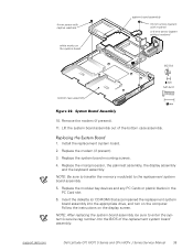
... system board assembly, be sure to the replacement system board assembly. 5. Replace the modem (if present). 3. NOTE: Be sure to transfer the memory module(s) to enter the system's service tag number into the appropriate drive, and turn on the computer. Replace the system board mounting screws. 4. ...marks on the display screen. 4-mm screw with modem) or 4-mm screw (system without modem) M2.5x4 M2.5x10 10. support.dell.com Dell Latitude CPt V/CPt S Series and CPx H/CPx J Series Service Manual 35 Lift the system board assembly out of the replacement system board assembly.
... system board assembly, be sure to the replacement system board assembly. 5. Replace the modem (if present). 3. NOTE: Be sure to transfer the memory module(s) to enter the system's service tag number into the appropriate drive, and turn on the computer. Replace the system board mounting screws. 4. ...marks on the display screen. 4-mm screw with modem) or 4-mm screw (system without modem) M2.5x4 M2.5x10 10. support.dell.com Dell Latitude CPt V/CPt S Series and CPx H/CPx J Series Service Manual 35 Lift the system board assembly out of the replacement system board assembly.
Service Manual
Page 47
... bay devices removal, 12 module latch assemblies removal, 37 screw identification and tightening, 3 sockets memory module, 13 SuperDisk LS-120 drive removal, 12 system board assembly removal, 18 thermal cooling assembly removal, 36 tools, 2 travel module removal, 12 ZIF connectors, 5 palmrest assembly removal, 30 2 Dell Latitude CPt V/CPt S Series and CPx H/Cpx J Series Service Manual
... bay devices removal, 12 module latch assemblies removal, 37 screw identification and tightening, 3 sockets memory module, 13 SuperDisk LS-120 drive removal, 12 system board assembly removal, 18 thermal cooling assembly removal, 36 tools, 2 travel module removal, 12 ZIF connectors, 5 palmrest assembly removal, 30 2 Dell Latitude CPt V/CPt S Series and CPx H/Cpx J Series Service Manual

System Information Guide (multilanguage: English, Japanese, Chinese-Traditional, Chinese-Simplified, Korean, Thai)
Page 12
...Before you connect a cable make sure both connectors are asked to the cloth; Hold a component such as a memory module by hand, be ready to sunlight. • When you pull out the connector, keep it to other...avoid bending any connector pins. Apply the cleaner to turn it off the computer before removing the memory module or disconnecting the device to help avoid possible damage to evaporate before you clean your computer ...after turning off , unplug it could slide around. Preliminary 1/25/00 1-8 Dell Latitude System Information You can put the drive through a metal detector.
...Before you connect a cable make sure both connectors are asked to the cloth; Hold a component such as a memory module by hand, be ready to sunlight. • When you pull out the connector, keep it to other...avoid bending any connector pins. Apply the cleaner to turn it off the computer before removing the memory module or disconnecting the device to help avoid possible damage to evaporate before you clean your computer ...after turning off , unplug it could slide around. Preliminary 1/25/00 1-8 Dell Latitude System Information You can put the drive through a metal detector.
System Information Guide (multilanguage: English, Japanese, Chinese-Traditional, Chinese-Simplified, Korean, Thai)
Page 14
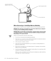
..., periodically touch the I /O) connector on the back of an input/output (I /O panel to dissipate any static electricity that might harm internal components. DELL CONFIDENTIAL - While you remove or install memory modules, observe the following safety guidelines: NOTE: For full instructions, see your User's Guide. • Turn off your computer and any attached..., if necessary, the secondary battery from the modular bay. • Ground yourself by touching the unpainted metal surface of the computer. Preliminary 1/25/00 1-10 Dell Latitude System Information
..., periodically touch the I /O) connector on the back of an input/output (I /O panel to dissipate any static electricity that might harm internal components. DELL CONFIDENTIAL - While you remove or install memory modules, observe the following safety guidelines: NOTE: For full instructions, see your User's Guide. • Turn off your computer and any attached..., if necessary, the secondary battery from the modular bay. • Ground yourself by touching the unpainted metal surface of the computer. Preliminary 1/25/00 1-10 Dell Latitude System Information
System Information Guide (multilanguage: English, Japanese, Chinese-Traditional, Chinese-Simplified, Korean, Thai)
Page 15
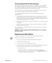
... in an antistatic container or packaging. • Handle all open files and application programs. 2. Save your work inside your Dell documentation to remind you continue to work and close all sensitive components in the battery bay, connect the computer to an electrical... replace the main battery in the System Setup program). Preliminary 1/25/00 Dell Latitude System Information 1-11 To prevent static damage, discharge static electricity from your computer's electronic components, such as a memory module. Just before unwrapping the antistatic packaging, be sure to discharge static ...
... in an antistatic container or packaging. • Handle all open files and application programs. 2. Save your work inside your Dell documentation to remind you continue to work and close all sensitive components in the battery bay, connect the computer to an electrical... replace the main battery in the System Setup program). Preliminary 1/25/00 Dell Latitude System Information 1-11 To prevent static damage, discharge static electricity from your computer's electronic components, such as a memory module. Just before unwrapping the antistatic packaging, be sure to discharge static ...


