
Service Manual
Page 16
Memory door assembly DOOR, MEM, MET, NB System board assembly, SVCKIT, MB ASSY, PWA, ENGINE 22 service kit Service tag installation diskette DSK, BIOS, FLDSVC, F3, US BIOS flash diskette KIT, BIOS, FLASH, UPG, F3 Diagnostic diskette KIT, DSK, DIAG, F3, WW System board assembly ASSY, PWA, ENGINE Main system board PWA, PLN, 0M... Kit, latch, slider, Button Foot, Rubber, Black (4 each) Foot, Rubber, Strike Zone, Black LTCH, BTN, Module Foot, Rbr, Blk Foot, Rbr, Strike Zone, Blk support.dell.com Dell Latitude CPt V/CPt S Series and CPx H/CPx J Series Service Manual 9
Memory door assembly DOOR, MEM, MET, NB System board assembly, SVCKIT, MB ASSY, PWA, ENGINE 22 service kit Service tag installation diskette DSK, BIOS, FLDSVC, F3, US BIOS flash diskette KIT, BIOS, FLASH, UPG, F3 Diagnostic diskette KIT, DSK, DIAG, F3, WW System board assembly ASSY, PWA, ENGINE Main system board PWA, PLN, 0M... Kit, latch, slider, Button Foot, Rubber, Black (4 each) Foot, Rubber, Strike Zone, Black LTCH, BTN, Module Foot, Rbr, Blk Foot, Rbr, Strike Zone, Blk support.dell.com Dell Latitude CPt V/CPt S Series and CPx H/CPx J Series Service Manual 9
Service Manual
Page 41
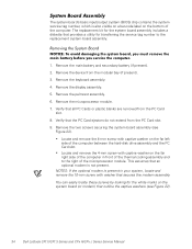
... bay (if present). 3. Remove the two screws securing the system board assembly (see Figure 22). 34 Dell Latitude CPt V/CPt S Series and CPx H/CPx J Series Service Manual Remove the microprocessor module. 7. The system board's basic input/output system (BIOS) chip contains the system service tag number, which is also visible on a bar-code label on...
... bay (if present). 3. Remove the two screws securing the system board assembly (see Figure 22). 34 Dell Latitude CPt V/CPt S Series and CPx H/CPx J Series Service Manual Remove the microprocessor module. 7. The system board's basic input/output system (BIOS) chip contains the system service tag number, which is also visible on a bar-code label on...
Service Manual
Page 42
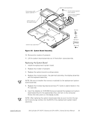
...assembly out of the replacement system board assembly. Insert the diskette (or CD-ROM) that accompanied the replacement system board assembly into the BIOS of the bottom case assembly. 1. Replace the modem (if present). 3. NOTE: Be sure to transfer the memory module(s) to enter ...sure to the replacement system board assembly. 5. Install the replacement system board. 2. Replace the system board mounting screws. 4. support.dell.com Dell Latitude CPt V/CPt S Series and CPx H/CPx J Series Service Manual 35 4-mm screw with modem) or 4-mm screw (system without modem) M2.5x4 M2.5x10 10. ...
...assembly out of the replacement system board assembly. Insert the diskette (or CD-ROM) that accompanied the replacement system board assembly into the BIOS of the bottom case assembly. 1. Replace the modem (if present). 3. NOTE: Be sure to transfer the memory module(s) to enter ...sure to the replacement system board assembly. 5. Install the replacement system board. 2. Replace the system board mounting screws. 4. support.dell.com Dell Latitude CPt V/CPt S Series and CPx H/CPx J Series Service Manual 35 4-mm screw with modem) or 4-mm screw (system without modem) M2.5x4 M2.5x10 10. ...

System Information Guide (multilanguage: English, Japanese, Chinese-Traditional, Chinese-Simplified, Korean, Thai)
Page 6
... steps 1 through 5, customizing the boot sequence to access the System Setup menu. 5. Preliminary 1/25/00 1-2 Dell Latitude System Information Turn on these help tools, see the "Getting Help" section in the online User's Guide. Press at the Dell BIOS splash screen to fit your computer does not perform as expected. Turn the computer off...
... steps 1 through 5, customizing the boot sequence to access the System Setup menu. 5. Preliminary 1/25/00 1-2 Dell Latitude System Information Turn on these help tools, see the "Getting Help" section in the online User's Guide. Press at the Dell BIOS splash screen to fit your computer does not perform as expected. Turn the computer off...


