
Setup Guide
Page 8
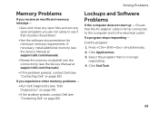
However, power connectors and power strips vary among countries. Using an incompatible cable or improperly connecting the cable to a power strip or electrical outlet may cause fire or permanent damage to the computer and then plug it into an electrical outlet or surge protector. WARNING: The AC adapter works with electrical outlets worldwide. Setting Up Your Inspiron Laptop Connect the AC Adapter Connect the AC adapter to your computer. 6
However, power connectors and power strips vary among countries. Using an incompatible cable or improperly connecting the cable to a power strip or electrical outlet may cause fire or permanent damage to the computer and then plug it into an electrical outlet or surge protector. WARNING: The AC adapter works with electrical outlets worldwide. Setting Up Your Inspiron Laptop Connect the AC Adapter Connect the AC adapter to your computer. 6
Setup Guide
Page 31
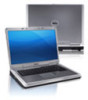
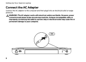
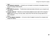
Connects your computer. 4 AC adapter connector - Connects to the AC adapter to the computer. Attaches a commercially available security cable to power the computer and charge the battery. 29 NOTE: Before you buy a security cable, ensure that it fits into the security cable slot on your computer to a network or broadband device if you are using a wired network. 2 USB 3.0 connector - Using Your Inspiron Laptop 1 Network connector - Provides faster data transmission between your computer and USB devices. 3 Security cable slot -
Connects your computer. 4 AC adapter connector - Connects to the AC adapter to the computer. Attaches a commercially available security cable to power the computer and charge the battery. 29 NOTE: Before you buy a security cable, ensure that it fits into the security cable slot on your computer to a network or broadband device if you are using a wired network. 2 USB 3.0 connector - Using Your Inspiron Laptop 1 Network connector - Provides faster data transmission between your computer and USB devices. 3 Security cable slot -

Setup Guide
Page 59
... network connection is lost - Check the network cable to ensure it is off or in hibernate mode. • Reseat the AC adapter cable into the power connector on the computer, into the AC adapter, and to the electrical outlet. 57 The computer resumes normal operation if it is plugged in hibernate mode, or is not...
... network connection is lost - Check the network cable to ensure it is off or in hibernate mode. • Reseat the AC adapter cable into the power connector on the computer, into the AC adapter, and to the electrical outlet. 57 The computer resumes normal operation if it is plugged in hibernate mode, or is not...
Setup Guide
Page 61
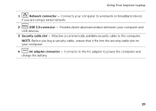
Ensure that the AC adapter cable is no longer responding. 4. Click Applications. 3. If you are not using to the electrical outlet. Lockups and Software Problems If the computer does not ... page 82). If necessary, install additional memory (see the Service Manual at support.dell.com/manuals). • Reseat the memory module(s) into the connector(s) (see the Service Manual at support.dell.com/manuals). • If the problem persists, contact Dell (see "Contacting Dell" on page 82). Select the program that resolves the problem. • See...
Ensure that the AC adapter cable is no longer responding. 4. Click Applications. 3. If you are not using to the electrical outlet. Lockups and Software Problems If the computer does not ... page 82). If necessary, install additional memory (see the Service Manual at support.dell.com/manuals). • Reseat the memory module(s) into the connector(s) (see the Service Manual at support.dell.com/manuals). • If the problem persists, contact Dell (see "Contacting Dell" on page 82). Select the program that resolves the problem. • See...
Setup Guide
Page 8
However, power connectors and power strips vary among countries. Using an incompatible cable or improperly connecting the cable to a power strip or electrical outlet may cause fire or permanent damage to the computer and then plug it into an electrical outlet or surge protector. WARNING: The AC adapter works with electrical outlets worldwide. Setting Up Your Inspiron Laptop Connect the AC Adapter Connect the AC adapter to your computer. 6
However, power connectors and power strips vary among countries. Using an incompatible cable or improperly connecting the cable to a power strip or electrical outlet may cause fire or permanent damage to the computer and then plug it into an electrical outlet or surge protector. WARNING: The AC adapter works with electrical outlets worldwide. Setting Up Your Inspiron Laptop Connect the AC Adapter Connect the AC adapter to your computer. 6
Setup Guide
Page 31
Connects to the AC adapter to a network or broadband device if you buy a security cable, ensure that it fits into the security cable slot on your computer. 4 AC adapter connector - NOTE: Before you are using a wired network. 2 USB 3.0 connector - Connects your computer and USB devices. 3 Security cable slot - Provides faster data transmission between your computer to power the computer and charge the battery. 29 Attaches a commercially available security cable to the computer. Using Your Inspiron Laptop 1 Network connector -
Connects to the AC adapter to a network or broadband device if you buy a security cable, ensure that it fits into the security cable slot on your computer. 4 AC adapter connector - NOTE: Before you are using a wired network. 2 USB 3.0 connector - Connects your computer and USB devices. 3 Security cable slot - Provides faster data transmission between your computer to power the computer and charge the battery. 29 Attaches a commercially available security cable to the computer. Using Your Inspiron Laptop 1 Network connector -

Service Manual
Page 7
19 Coin-Cell Battery 87 Removing the Coin-Cell Battery 87 Replacing the Coin-Cell Battery 88 20 Thermal Cooling Assembly 89 Removing the Thermal Cooling Assembly 89 Replacing the Thermal Cooling Assembly 90 21 Processor Module 91 Removing the Processor Module 91 Replacing the Processor Module 92 22 Hard-Drive Assembly 95 Removing the Hard-Drive Assembly 95 Replacing the Hard-Drive Assembly 97 23 I/O Board 99 Removing the I/O Board 99 Replacing the I/O Board 100 24 AC-Adapter Connector 101 Removing the AC-Adapter Connector 101 Contents 7
19 Coin-Cell Battery 87 Removing the Coin-Cell Battery 87 Replacing the Coin-Cell Battery 88 20 Thermal Cooling Assembly 89 Removing the Thermal Cooling Assembly 89 Replacing the Thermal Cooling Assembly 90 21 Processor Module 91 Removing the Processor Module 91 Replacing the Processor Module 92 22 Hard-Drive Assembly 95 Removing the Hard-Drive Assembly 95 Replacing the Hard-Drive Assembly 97 23 I/O Board 99 Removing the I/O Board 99 Replacing the I/O Board 100 24 AC-Adapter Connector 101 Removing the AC-Adapter Connector 101 Contents 7

Service Manual
Page 8
Replacing the AC-Adapter Connector 102 25 Flashing the BIOS 105 8 Contents
Replacing the AC-Adapter Connector 102 25 Flashing the BIOS 105 8 Contents
Service Manual
Page 77
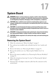
... from the 8-in "Removing the Optical Drive" on page 19. 7 Disconnect the AC-adapter connector cable from step 4 to the system board, remove the main battery (see the Regulatory Compliance Homepage at dell.com/regulatory_compliance. For additional safety best practices information, see "Removing the Battery" on ... discharge, ground yourself by using a wrist grounding strap or by periodically touching an unpainted metal surface (such as a connector on your computer. 17 System Board WARNING: Before working inside your computer, read the safety information that is not authorized by...
... from the 8-in "Removing the Optical Drive" on page 19. 7 Disconnect the AC-adapter connector cable from step 4 to the system board, remove the main battery (see the Regulatory Compliance Homepage at dell.com/regulatory_compliance. For additional safety best practices information, see "Removing the Battery" on ... discharge, ground yourself by using a wrist grounding strap or by periodically touching an unpainted metal surface (such as a connector on your computer. 17 System Board WARNING: Before working inside your computer, read the safety information that is not authorized by...

Service Manual
Page 78
1 1 AC-adapter connector cable 8 Remove the keyboard (see "Removing the Keyboard" on page 27). 9 Remove the palm-rest assembly (see "Removing the Palm-Rest Assembly" on page 31). 10 Remove the thermal fan (see "Removing the Thermal Fan" on page 49). 11 Loosen the display cable grounding screw. 12 Disconnect the display cable and speakers cable from the connectors on the system board. 13 Remove the five screws that secure the system board to the computer base. 78 System Board
1 1 AC-adapter connector cable 8 Remove the keyboard (see "Removing the Keyboard" on page 27). 9 Remove the palm-rest assembly (see "Removing the Palm-Rest Assembly" on page 31). 10 Remove the thermal fan (see "Removing the Thermal Fan" on page 49). 11 Loosen the display cable grounding screw. 12 Disconnect the display cable and speakers cable from the connectors on the system board. 13 Remove the five screws that secure the system board to the computer base. 78 System Board
Service Manual
Page 81
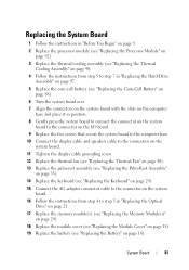
...I/O board. 9 Replace the five screws that secure the system board to the computer base. 10 Connect the display cable and speakers cable to the connectors on the system board. 11 Tighten the display cable grounding screw. 12 Replace the thermal fan (see "Replacing the Thermal Fan" on page 50)....see "Replacing the Palm-Rest Assembly" on page 35). 14 Replace the keyboard (see "Replacing the Keyboard" on page 29). 15 Connect the AC-adapter connector cable to the connector on the system board. 16 Follow the instructions from step 4 to step 5 in "Replacing the Optical Drive" on page 21. 17 Replace the...
...I/O board. 9 Replace the five screws that secure the system board to the computer base. 10 Connect the display cable and speakers cable to the connectors on the system board. 11 Tighten the display cable grounding screw. 12 Replace the thermal fan (see "Replacing the Thermal Fan" on page 50)....see "Replacing the Palm-Rest Assembly" on page 35). 14 Replace the keyboard (see "Replacing the Keyboard" on page 29). 15 Connect the AC-adapter connector cable to the connector on the system board. 16 Follow the instructions from step 4 to step 5 in "Replacing the Optical Drive" on page 21. 17 Replace the...
Service Manual
Page 101
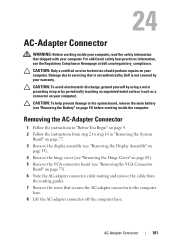
..., remove the main battery (see the Regulatory Compliance Homepage at dell.com/regulatory_compliance. AC-Adapter Connector 101 24 AC-Adapter Connector WARNING: Before working inside your computer, read the safety information that is not authorized by Dell is not covered by periodically touching an unpainted metal surface (such as a connector on your computer). CAUTION: To help prevent damage to...
..., remove the main battery (see the Regulatory Compliance Homepage at dell.com/regulatory_compliance. AC-Adapter Connector 101 24 AC-Adapter Connector WARNING: Before working inside your computer, read the safety information that is not authorized by Dell is not covered by periodically touching an unpainted metal surface (such as a connector on your computer). CAUTION: To help prevent damage to...

Service Manual
Page 102
... page 81. CAUTION: Before turning on the computer, replace all screws and ensure that secures the AC-adapter connector to the computer base. 4 Route the AC-adapter connector cable through the routing guides. 5 Replace the VGA connector board (see "Replacing the VGA Connector Board" on page 74). 6 Replace the hinge cover (see "Replacing the Hinge Cover" on page...
... page 81. CAUTION: Before turning on the computer, replace all screws and ensure that secures the AC-adapter connector to the computer base. 4 Route the AC-adapter connector cable through the routing guides. 5 Replace the VGA connector board (see "Replacing the VGA Connector Board" on page 74). 6 Replace the hinge cover (see "Replacing the Hinge Cover" on page...

Service Manual
Page 7
19 Coin-Cell Battery 87 Removing the Coin-Cell Battery 87 Replacing the Coin-Cell Battery 88 20 Thermal Cooling Assembly 89 Removing the Thermal Cooling Assembly 89 Replacing the Thermal Cooling Assembly 90 21 Processor Module 91 Removing the Processor Module 91 Replacing the Processor Module 92 22 Hard-Drive Assembly 95 Removing the Hard-Drive Assembly 95 Replacing the Hard-Drive Assembly 97 23 I/O Board 99 Removing the I/O Board 99 Replacing the I/O Board 100 24 AC-Adapter Connector 101 Removing the AC-Adapter Connector 101 Contents 7
19 Coin-Cell Battery 87 Removing the Coin-Cell Battery 87 Replacing the Coin-Cell Battery 88 20 Thermal Cooling Assembly 89 Removing the Thermal Cooling Assembly 89 Replacing the Thermal Cooling Assembly 90 21 Processor Module 91 Removing the Processor Module 91 Replacing the Processor Module 92 22 Hard-Drive Assembly 95 Removing the Hard-Drive Assembly 95 Replacing the Hard-Drive Assembly 97 23 I/O Board 99 Removing the I/O Board 99 Replacing the I/O Board 100 24 AC-Adapter Connector 101 Removing the AC-Adapter Connector 101 Contents 7

Service Manual
Page 8
Replacing the AC-Adapter Connector 102 25 Flashing the BIOS 105 8 Contents
Replacing the AC-Adapter Connector 102 25 Flashing the BIOS 105 8 Contents

Service Manual
Page 77
...6 Follow the instructions from step 4 to step 5 in "Removing the Optical Drive" on page 19. 7 Disconnect the AC-adapter connector cable from the connector on page 15) before working inside the computer. CAUTION: To help prevent damage to servicing that shipped with your computer. Damage...WARNING: Before working inside your computer, read the safety information that is not authorized by Dell is not covered by periodically touching an unpainted metal surface (such as a connector on your computer. For additional safety best practices information, see "Removing the Battery" on...
...6 Follow the instructions from step 4 to step 5 in "Removing the Optical Drive" on page 19. 7 Disconnect the AC-adapter connector cable from the connector on page 15) before working inside the computer. CAUTION: To help prevent damage to servicing that shipped with your computer. Damage...WARNING: Before working inside your computer, read the safety information that is not authorized by Dell is not covered by periodically touching an unpainted metal surface (such as a connector on your computer. For additional safety best practices information, see "Removing the Battery" on...

Service Manual
Page 78
1 1 AC-adapter connector cable 8 Remove the keyboard (see "Removing the Keyboard" on page 27). 9 Remove the palm-rest assembly (see "Removing the Palm-Rest Assembly" on page 31). 10 Remove the thermal fan (see "Removing the Thermal Fan" on page 49). 11 Loosen the display cable grounding screw. 12 Disconnect the display cable and speakers cable from the connectors on the system board. 13 Remove the five screws that secure the system board to the computer base. 78 System Board
1 1 AC-adapter connector cable 8 Remove the keyboard (see "Removing the Keyboard" on page 27). 9 Remove the palm-rest assembly (see "Removing the Palm-Rest Assembly" on page 31). 10 Remove the thermal fan (see "Removing the Thermal Fan" on page 49). 11 Loosen the display cable grounding screw. 12 Disconnect the display cable and speakers cable from the connectors on the system board. 13 Remove the five screws that secure the system board to the computer base. 78 System Board

Service Manual
Page 81
...I/O board. 9 Replace the five screws that secure the system board to the computer base. 10 Connect the display cable and speakers cable to the connectors on the system board. 11 Tighten the display cable grounding screw. 12 Replace the thermal fan (see "Replacing the Thermal Fan" on page 50)....see "Replacing the Palm-Rest Assembly" on page 35). 14 Replace the keyboard (see "Replacing the Keyboard" on page 29). 15 Connect the AC-adapter connector cable to the connector on the system board. 16 Follow the instructions from step 4 to step 5 in "Replacing the Optical Drive" on page 21. 17 Replace the...
...I/O board. 9 Replace the five screws that secure the system board to the computer base. 10 Connect the display cable and speakers cable to the connectors on the system board. 11 Tighten the display cable grounding screw. 12 Replace the thermal fan (see "Replacing the Thermal Fan" on page 50)....see "Replacing the Palm-Rest Assembly" on page 35). 14 Replace the keyboard (see "Replacing the Keyboard" on page 29). 15 Connect the AC-adapter connector cable to the connector on the system board. 16 Follow the instructions from step 4 to step 5 in "Replacing the Optical Drive" on page 21. 17 Replace the...

Service Manual
Page 101
... the cable from step 2 to the computer base. 8 Lift the AC-adapter connector off the computer base. AC-Adapter Connector 101 Removing the AC-Adapter Connector 1 Follow the instructions in "Before You Begin" on your computer). For additional safety best practices information, see the Regulatory Compliance Homepage at dell.com/regulatory_compliance. CAUTION: Only a certified service technician should perform repairs on...
... the cable from step 2 to the computer base. 8 Lift the AC-adapter connector off the computer base. AC-Adapter Connector 101 Removing the AC-Adapter Connector 1 Follow the instructions in "Before You Begin" on your computer). For additional safety best practices information, see the Regulatory Compliance Homepage at dell.com/regulatory_compliance. CAUTION: Only a certified service technician should perform repairs on...

Service Manual
Page 102
...on the computer, replace all screws and ensure that secures the AC-adapter connector to the computer base. 4 Route the AC-adapter connector cable through the routing guides. 5 Replace the VGA connector board (see "Replacing the VGA Connector Board" on page 74). 6 Replace the hinge cover (see... step 7 to the computer. 102 AC-Adapter Connector Failure to do so may result in damage to step 20 in "Before You Begin" on page 9. 2 Place the AC-adapter connector on page 81. 1 2 1 screw 2 AC-adapter connector cable Replacing the AC-Adapter Connector 1 Follow the instructions in "Replacing the...
...on the computer, replace all screws and ensure that secures the AC-adapter connector to the computer base. 4 Route the AC-adapter connector cable through the routing guides. 5 Replace the VGA connector board (see "Replacing the VGA Connector Board" on page 74). 6 Replace the hinge cover (see... step 7 to the computer. 102 AC-Adapter Connector Failure to do so may result in damage to step 20 in "Before You Begin" on page 9. 2 Place the AC-adapter connector on page 81. 1 2 1 screw 2 AC-adapter connector cable Replacing the AC-Adapter Connector 1 Follow the instructions in "Replacing the...


