Setup Guide
Page 5
... Adapter 6 Connect the Network Cable (Optional 7 Press the Power Button 8 Set Up the Operating System 9 Create System Recovery Media (Recommended 10 Install the SIM Card (Optional 12 Enable or Disable Wireless (Optional 14 Set Up Wireless Display (Optional 16 Connect to the Internet (Optional 18 Using Your Inspiron Laptop 22 Right View Features 22 Left View Features 24 Back View Features 28 Front View Features 30 Status Lights and Indicators 32 Disabling Battery Charging 33 Computer Base and Keyboard Features 34 Touch Pad Gestures 38 Multimedia Control Keys...
... Adapter 6 Connect the Network Cable (Optional 7 Press the Power Button 8 Set Up the Operating System 9 Create System Recovery Media (Recommended 10 Install the SIM Card (Optional 12 Enable or Disable Wireless (Optional 14 Set Up Wireless Display (Optional 16 Connect to the Internet (Optional 18 Using Your Inspiron Laptop 22 Right View Features 22 Left View Features 24 Back View Features 28 Front View Features 30 Status Lights and Indicators 32 Disabling Battery Charging 33 Computer Base and Keyboard Features 34 Touch Pad Gestures 38 Multimedia Control Keys...
Setup Guide
Page 6
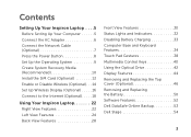
... Problems 56 Beep Codes 56 Network Problems 57 Power Problems 57 Memory Problems 59 Lockups and Software Problems 59 Using Support Tools 62 Dell Support Center 62 My Dell Downloads 63 Hardware Troubleshooter 64 Dell Diagnostics 64 Restoring Your Operating System 66 System Restore 67 Dell DataSafe Local Backup 68 System Recovery Media 71 Dell Factory Image Restore 72 Getting Help 74 Technical Support and Customer Service 75 DellConnect 75 Online Services 76 Automated Order-Status Service 77 Product Information 77 Returning Items for Repair...
... Problems 56 Beep Codes 56 Network Problems 57 Power Problems 57 Memory Problems 59 Lockups and Software Problems 59 Using Support Tools 62 Dell Support Center 62 My Dell Downloads 63 Hardware Troubleshooter 64 Dell Diagnostics 64 Restoring Your Operating System 66 System Restore 67 Dell DataSafe Local Backup 68 System Recovery Media 71 Dell Factory Image Restore 72 Getting Help 74 Technical Support and Customer Service 75 DellConnect 75 Online Services 76 Automated Order-Status Service 77 Product Information 77 Returning Items for Repair...
Setup Guide
Page 19
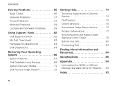
Select Connect to Existing Adapter. NOTE: For more information about wireless display, see the wireless display adapter documentation. Click the Intel Wireless Display icon on the desktop. The Intel Wireless Display window appears. 2. NOTE: You can download and install the latest driver for "Intel Wireless Display Connection Manager" from support.dell.com. Setting Up Your Inspiron Laptop 17 To enable wireless display: 1.
Select Connect to Existing Adapter. NOTE: For more information about wireless display, see the wireless display adapter documentation. Click the Intel Wireless Display icon on the desktop. The Intel Wireless Display window appears. 2. NOTE: You can download and install the latest driver for "Intel Wireless Display Connection Manager" from support.dell.com. Setting Up Your Inspiron Laptop 17 To enable wireless display: 1.
Setup Guide
Page 60
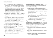
... AC adapter is on. • If the problem persists, contact Dell (see "Contacting Dell" on page 82). If you encounter interference that hinders reception on page 82). The computer is in standby mode or the display may not be responding. • Press a key on the keyboard, move the connected mouse or a finger on the touch pad, or press the power button to resume normal operation...
... AC adapter is on. • If the problem persists, contact Dell (see "Contacting Dell" on page 82). If you encounter interference that hinders reception on page 82). The computer is in standby mode or the display may not be responding. • Press a key on the keyboard, move the connected mouse or a finger on the touch pad, or press the power button to resume normal operation...
Setup Guide
Page 61
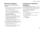
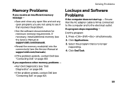
... the Service Manual at support.dell.com/manuals). • Reseat the memory module(s) into the connector(s) (see the Service Manual at support.dell.com/manuals). • If the problem persists, contact Dell (see "Contacting Dell" on page 82). Select the program that is firmly connected to the computer and to see if that the AC adapter cable is no longer responding. 4. Ensure that resolves the problem. • See the software...
... the Service Manual at support.dell.com/manuals). • Reseat the memory module(s) into the connector(s) (see the Service Manual at support.dell.com/manuals). • If the problem persists, contact Dell (see "Contacting Dell" on page 82). Select the program that is firmly connected to the computer and to see if that the AC adapter cable is no longer responding. 4. Ensure that resolves the problem. • See the software...
Setup Guide
Page 88
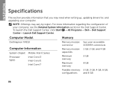
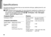
... Model Memory Dell Inspiron N4110 Computer Information System chipset Mobile Intel 6 Series Processor types Intel Core i3 Intel Core i5 Intel Core i7 Memory module connector Memory module capacities Minimum memory Maximum memory two user-accessible SODIMM connectors 1 GB, 2 GB, and 4 GB 2 GB 8 GB Possible memory 2 GB, 3 GB, 4 GB, 6 GB, configurations and 8 GB 86 INSPIRON Specifications This section provides information that you may vary by region. To launch the Dell Support...
... Model Memory Dell Inspiron N4110 Computer Information System chipset Mobile Intel 6 Series Processor types Intel Core i3 Intel Core i5 Intel Core i7 Memory module connector Memory module capacities Minimum memory Maximum memory two user-accessible SODIMM connectors 1 GB, 2 GB, and 4 GB 2 GB 8 GB Possible memory 2 GB, 3 GB, 4 GB, 6 GB, configurations and 8 GB 86 INSPIRON Specifications This section provides information that you may vary by region. To launch the Dell Support...
Setup Guide
Page 99
problems, solving 56 products information and purchasing 77 R resources, finding more 84 restoring factory image 72 S Service Tag locating 80 setup, before you begin 5 shipping products for return or repair 78 SIM card 12 software features 52 software problems 59 solving problems 56 specifications 86 support e-mail addresses 76 support sites worldwide 76 System Recovery Media 71 system reinstall options 66 System Restore 67 T Touch Pad Gestures 38 U Using the Emergency Eject Hole 42 V ventilation, ensuring 5 Index 97
problems, solving 56 products information and purchasing 77 R resources, finding more 84 restoring factory image 72 S Service Tag locating 80 setup, before you begin 5 shipping products for return or repair 78 SIM card 12 software features 52 software problems 59 solving problems 56 specifications 86 support e-mail addresses 76 support sites worldwide 76 System Recovery Media 71 system reinstall options 66 System Restore 67 T Touch Pad Gestures 38 U Using the Emergency Eject Hole 42 V ventilation, ensuring 5 Index 97
Setup Guide
Page 5
... Adapter 6 Connect the Network Cable (Optional 7 Press the Power Button 8 Set Up the Operating System 9 Create System Recovery Media (Recommended 10 Install the SIM Card (Optional 12 Enable or Disable Wireless (Optional 14 Set Up Wireless Display (Optional 16 Connect to the Internet (Optional 18 Using Your Inspiron Laptop 22 Right View Features 22 Left View Features 24 Back View Features 28 Front View Features 30 Status Lights and Indicators 32 Disabling Battery Charging 33 Computer Base and Keyboard Features 34 Touch Pad Gestures 38 Multimedia Control Keys...
... Adapter 6 Connect the Network Cable (Optional 7 Press the Power Button 8 Set Up the Operating System 9 Create System Recovery Media (Recommended 10 Install the SIM Card (Optional 12 Enable or Disable Wireless (Optional 14 Set Up Wireless Display (Optional 16 Connect to the Internet (Optional 18 Using Your Inspiron Laptop 22 Right View Features 22 Left View Features 24 Back View Features 28 Front View Features 30 Status Lights and Indicators 32 Disabling Battery Charging 33 Computer Base and Keyboard Features 34 Touch Pad Gestures 38 Multimedia Control Keys...

Setup Guide
Page 6
... Problems 56 Beep Codes 56 Network Problems 57 Power Problems 57 Memory Problems 59 Lockups and Software Problems 59 Using Support Tools 62 Dell Support Center 62 My Dell Downloads 63 Hardware Troubleshooter 64 Dell Diagnostics 64 Restoring Your Operating System 66 System Restore 67 Dell DataSafe Local Backup 68 System Recovery Media 71 Dell Factory Image Restore 72 Getting Help 74 Technical Support and Customer Service 75 DellConnect 75 Online Services 76 Automated Order-Status Service 77 Product Information 77 Returning Items for Repair...
... Problems 56 Beep Codes 56 Network Problems 57 Power Problems 57 Memory Problems 59 Lockups and Software Problems 59 Using Support Tools 62 Dell Support Center 62 My Dell Downloads 63 Hardware Troubleshooter 64 Dell Diagnostics 64 Restoring Your Operating System 66 System Restore 67 Dell DataSafe Local Backup 68 System Recovery Media 71 Dell Factory Image Restore 72 Getting Help 74 Technical Support and Customer Service 75 DellConnect 75 Online Services 76 Automated Order-Status Service 77 Product Information 77 Returning Items for Repair...

Setup Guide
Page 58
... the Service Manual at support.dell.com. Beep Codes Your computer might emit a series of beeps during start-up if there are errors or problems. This series of beeps, called a beep code, identifies a problem. Three Possible system board failure - WARNING: Only trained service personnel should remove the computer cover. INSPIRON Solving Problems This section provides troubleshooting information for assistance. Beep Possible Problem Code One Possible system board failure - BIOS ROM checksum failure Two No RAM...
... the Service Manual at support.dell.com. Beep Codes Your computer might emit a series of beeps during start-up if there are errors or problems. This series of beeps, called a beep code, identifies a problem. Three Possible system board failure - WARNING: Only trained service personnel should remove the computer cover. INSPIRON Solving Problems This section provides troubleshooting information for assistance. Beep Possible Problem Code One Possible system board failure - BIOS ROM checksum failure Two No RAM...
Setup Guide
Page 61
...). • If the problem persists, contact Dell (see "Contacting Dell" on page 82). Click Applications. 3. If necessary, install additional memory (see the Service Manual at support.dell.com/manuals). • Reseat the memory module(s) into the connector(s) (see the Service Manual at support.dell.com/manuals). • If the problem persists, contact Dell (see "Contacting Dell" on page 82). Lockups and Software Problems If the computer does not start up - Ensure that resolves...
...). • If the problem persists, contact Dell (see "Contacting Dell" on page 82). Click Applications. 3. If necessary, install additional memory (see the Service Manual at support.dell.com/manuals). • Reseat the memory module(s) into the connector(s) (see the Service Manual at support.dell.com/manuals). • If the problem persists, contact Dell (see "Contacting Dell" on page 82). Lockups and Software Problems If the computer does not start up - Ensure that resolves...
Setup Guide
Page 88
Computer Model Memory Dell Inspiron N4110 Computer Information System chipset Mobile Intel 6 Series Processor types Intel Core i3 Intel Core i5 Intel Core i7 Intel Pentium Dual Core Memory module connector Memory module capacities Minimum memory Maximum memory Possible memory configurations two user-accessible SODIMM connectors 1 GB, 2 GB, and 4 GB 2 GB 8 GB 2 GB, 3 GB, 4 GB, 6 GB, and 8 GB 86 For more information regarding the configuration of your computer. To...
Computer Model Memory Dell Inspiron N4110 Computer Information System chipset Mobile Intel 6 Series Processor types Intel Core i3 Intel Core i5 Intel Core i7 Intel Pentium Dual Core Memory module connector Memory module capacities Minimum memory Maximum memory Possible memory configurations two user-accessible SODIMM connectors 1 GB, 2 GB, and 4 GB 2 GB 8 GB 2 GB, 3 GB, 4 GB, 6 GB, and 8 GB 86 For more information regarding the configuration of your computer. To...
Setup Guide
Page 99
problems, solving 56 products information and purchasing 77 R resources, finding more 84 restoring factory image 72 S Service Tag locating 80 setup, before you begin 5 shipping products for return or repair 78 SIM card 12 software features 52 software problems 59 solving problems 56 specifications 86 support e-mail addresses 76 support sites worldwide 76 System Recovery Media 71 system reinstall options 66 System Restore 67 T Touch Pad Gestures 38 U Using the Emergency Eject Hole 42 V ventilation, ensuring 5 W warranty returns 78 Windows Index 97
problems, solving 56 products information and purchasing 77 R resources, finding more 84 restoring factory image 72 S Service Tag locating 80 setup, before you begin 5 shipping products for return or repair 78 SIM card 12 software features 52 software problems 59 solving problems 56 specifications 86 support e-mail addresses 76 support sites worldwide 76 System Recovery Media 71 system reinstall options 66 System Restore 67 T Touch Pad Gestures 38 U Using the Emergency Eject Hole 42 V ventilation, ensuring 5 W warranty returns 78 Windows Index 97

Service Manual
Page 4
Replacing the Optical Drive 21 6 Memory Module(s 23 Removing the Memory Module(s 23 Replacing the Memory Module(s 24 7 Keyboard 27 Removing the Keyboard 27 Replacing the Keyboard 29 8 Palm-Rest Assembly 31 Removing the Palm-Rest Assembly 31 Replacing the Palm-Rest Assembly 34 9 Hot-Key Board 37 Removing the Hot-Key Board 37 Replacing the Hot-Key Board 38 10 Power Button Board 41 Removing the Power Button Board 41 Replacing the Power Button Board 42 4 Contents
Replacing the Optical Drive 21 6 Memory Module(s 23 Removing the Memory Module(s 23 Replacing the Memory Module(s 24 7 Keyboard 27 Removing the Keyboard 27 Replacing the Keyboard 29 8 Palm-Rest Assembly 31 Removing the Palm-Rest Assembly 31 Replacing the Palm-Rest Assembly 34 9 Hot-Key Board 37 Removing the Hot-Key Board 37 Replacing the Hot-Key Board 38 10 Power Button Board 41 Removing the Power Button Board 41 Replacing the Power Button Board 42 4 Contents

Service Manual
Page 24
1 3 2 1 memory-module connector 2 securing clips (2) 3 memory module Replacing the Memory Module(s) CAUTION: If you need to install memory modules in two connectors, install a memory module in the connector labeled "DIMM A" before you do not hear the click, remove the memory module and reinstall it clicks into the slot at a 45-degree angle, and press the memory module down until it . If you install a memory module in the connector labeled "DIMM B." 1 Follow the instructions in "Before...
1 3 2 1 memory-module connector 2 securing clips (2) 3 memory module Replacing the Memory Module(s) CAUTION: If you need to install memory modules in two connectors, install a memory module in the connector labeled "DIMM A" before you do not hear the click, remove the memory module and reinstall it clicks into the slot at a 45-degree angle, and press the memory module down until it . If you install a memory module in the connector labeled "DIMM B." 1 Follow the instructions in "Before...

Service Manual
Page 48
... Optical Drive" on page 21. 10 Replace the module cover (see "Replacing the Module Cover" on page 18). 11 Replace the battery (see "Replacing the Keyboard" on page 29). 9 Follow the instructions from a source other end of the Mini-Card down into the slot on the system board and replace the screw that no stray screws remain inside the computer. The following table provides the antenna cable...
... Optical Drive" on page 21. 10 Replace the module cover (see "Replacing the Module Cover" on page 18). 11 Replace the battery (see "Replacing the Keyboard" on page 29). 9 Follow the instructions from a source other end of the Mini-Card down into the slot on the system board and replace the screw that no stray screws remain inside the computer. The following table provides the antenna cable...
Service Manual
Page 97
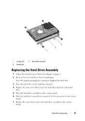
... hard-drive assembly to the system board. Save the original packaging for storing or shipping the hard drive. 3 Place the hard drive in "Before You Begin" on the system board. 7 Replace the screw that secure the hard-drive bracket to the hard drive. 5 Place the hard-drive assembly on the system board. 6 Slide the hard-drive assembly to connect it to the connector on page 9. 2 Remove the new hard drive from its packaging. Hard-Drive...
... hard-drive assembly to the system board. Save the original packaging for storing or shipping the hard drive. 3 Place the hard drive in "Before You Begin" on the system board. 7 Replace the screw that secure the hard-drive bracket to the hard drive. 5 Place the hard-drive assembly on the system board. 6 Slide the hard-drive assembly to connect it to the connector on page 9. 2 Remove the new hard drive from its packaging. Hard-Drive...

Service Manual
Page 4
Replacing the Optical Drive 21 6 Memory Module(s 23 Removing the Memory Module(s 23 Replacing the Memory Module(s 24 7 Keyboard 27 Removing the Keyboard 27 Replacing the Keyboard 29 8 Palm-Rest Assembly 31 Removing the Palm-Rest Assembly 31 Replacing the Palm-Rest Assembly 34 9 Hot-Key Board 37 Removing the Hot-Key Board 37 Replacing the Hot-Key Board 38 10 Power Button Board 41 Removing the Power Button Board 41 Replacing the Power Button Board 42 4 Contents
Replacing the Optical Drive 21 6 Memory Module(s 23 Removing the Memory Module(s 23 Replacing the Memory Module(s 24 7 Keyboard 27 Removing the Keyboard 27 Replacing the Keyboard 29 8 Palm-Rest Assembly 31 Removing the Palm-Rest Assembly 31 Replacing the Palm-Rest Assembly 34 9 Hot-Key Board 37 Removing the Hot-Key Board 37 Replacing the Hot-Key Board 38 10 Power Button Board 41 Removing the Power Button Board 41 Replacing the Power Button Board 42 4 Contents

Service Manual
Page 18
Failure to the computer. 18 Module Cover 1 2 3 1 captive screw 2 module cover 3 tabs (2) Replacing the Module Cover 1 Follow the instructions in "Before You Begin" on page 9. 2 Align the tabs on the module cover with the slots on page 16). CAUTION: Before turning on the computer, replace all screws and ensure that secures the module cover to the computer base. 4 Replace the battery (see "Replacing the Battery" on the computer base and gently snap the cover in damage to do so may result in place. 3 Tighten the captive screw that no stray screws remain inside the computer.
Failure to the computer. 18 Module Cover 1 2 3 1 captive screw 2 module cover 3 tabs (2) Replacing the Module Cover 1 Follow the instructions in "Before You Begin" on page 9. 2 Align the tabs on the module cover with the slots on page 16). CAUTION: Before turning on the computer, replace all screws and ensure that secures the module cover to the computer base. 4 Replace the battery (see "Replacing the Battery" on the computer base and gently snap the cover in damage to do so may result in place. 3 Tighten the captive screw that no stray screws remain inside the computer.
Service Manual
Page 48
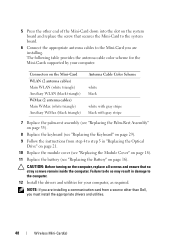
... so may result in "Replacing the Optical Drive" on page 21. 10 Replace the module cover (see "Replacing the Module Cover" on page 18). 11 Replace the battery (see "Replacing the Battery" on the computer, replace all screws and ensure that secures the Mini-Card to the system board. 6 Connect the appropriate antenna cables to the computer. 12 Install the drivers and utilities for the Mini-Cards supported by your computer, as...
... so may result in "Replacing the Optical Drive" on page 21. 10 Replace the module cover (see "Replacing the Module Cover" on page 18). 11 Replace the battery (see "Replacing the Battery" on the computer, replace all screws and ensure that secures the Mini-Card to the system board. 6 Connect the appropriate antenna cables to the computer. 12 Install the drivers and utilities for the Mini-Cards supported by your computer, as...


