Service Manual
Page 5
... the Thermal Fan 50 13 Display 53 Display Assembly 53 Removing the Display Assembly 53 Replacing the Display Assembly 56 Display Bezel 57 Removing the Display Bezel 57 Replacing the Display Bezel 58 Display Panel 58 Removing the Display Panel 58 Replacing the Display Panel 59 Display Cable 60 Removing the Display Cable...
... the Thermal Fan 50 13 Display 53 Display Assembly 53 Removing the Display Assembly 53 Replacing the Display Assembly 56 Display Bezel 57 Removing the Display Bezel 57 Replacing the Display Bezel 58 Display Panel 58 Removing the Display Panel 58 Replacing the Display Panel 59 Display Cable 60 Removing the Display Cable...

Service Manual
Page 20
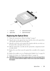
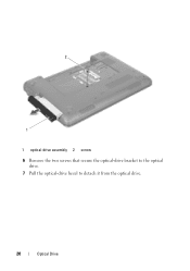
2 1 1 optical-drive assembly 2 screw 6 Remove the two screws that secure the optical-drive bracket to the optical drive. 7 Pull the optical-drive bezel to detach it from the optical drive. 20 Optical Drive
2 1 1 optical-drive assembly 2 screw 6 Remove the two screws that secure the optical-drive bracket to the optical drive. 7 Pull the optical-drive bezel to detach it from the optical drive. 20 Optical Drive
Service Manual
Page 21
... so may result in "Before You Begin" on page 9. 2 Align the tabs on the optical-drive bezel with the slots on the optical drive and snap the optical-drive bezel into place. 3 Align the screw holes on the optical-drive bracket with the screw holes on the optical... seated. 5 Replace the screw that secures the optical-drive assembly to the computer. 4 1 2 3 1 screws (2) 3 optical drive 2 optical-drive bracket 4 optical-drive bezel Replacing the Optical Drive 1 Follow the instructions in damage to the computer base. 6 Replace the module cover (see "Replacing the Module Cover" on page 18...
... so may result in "Before You Begin" on page 9. 2 Align the tabs on the optical-drive bezel with the slots on the optical drive and snap the optical-drive bezel into place. 3 Align the screw holes on the optical-drive bracket with the screw holes on the optical... seated. 5 Replace the screw that secures the optical-drive assembly to the computer. 4 1 2 3 1 screws (2) 3 optical drive 2 optical-drive bracket 4 optical-drive bezel Replacing the Optical Drive 1 Follow the instructions in damage to the computer base. 6 Replace the module cover (see "Replacing the Module Cover" on page 18...

Service Manual
Page 57
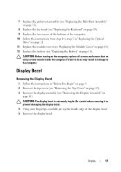
... module cover (see "Replacing the Module Cover" on page 18). 12 Replace the battery (see "Removing the Display Assembly" on page 16). Display Bezel Removing the Display Bezel 1 Follow the instructions in "Before You Begin" on page 9. 2 Remove the top cover (see "Removing the Top Cover" on page 13)....). 8 Replace the keyboard (see "Replacing the Keyboard" on page 29). 9 Replace the two screws at the bottom of the display bezel. 5 Remove the display bezel. CAUTION: Before turning on the computer, replace all screws and ensure that no stray screws remain inside edge of the computer. 10 Follow...
... module cover (see "Replacing the Module Cover" on page 18). 12 Replace the battery (see "Removing the Display Assembly" on page 16). Display Bezel Removing the Display Bezel 1 Follow the instructions in "Before You Begin" on page 9. 2 Remove the top cover (see "Removing the Top Cover" on page 13)....). 8 Replace the keyboard (see "Replacing the Keyboard" on page 29). 9 Replace the two screws at the bottom of the display bezel. 5 Remove the display bezel. CAUTION: Before turning on the computer, replace all screws and ensure that no stray screws remain inside edge of the computer. 10 Follow...

Service Manual
Page 58
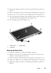
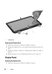
Display Panel Removing the Display Panel 1 Follow the instructions in "Before You Begin" on page 9. 2 Realign the display bezel over the display panel and gently snap it into place. 3 Replace the display assembly (see "Replacing the Display Assembly" on page 56). 4 Replace the top cover (see "Replacing the Top Cover" on page 9. 58 Display 1 1 display bezel Replacing the Display Bezel 1 Follow the instructions in "Before You Begin" on page 14).
Display Panel Removing the Display Panel 1 Follow the instructions in "Before You Begin" on page 9. 2 Realign the display bezel over the display panel and gently snap it into place. 3 Replace the display assembly (see "Replacing the Display Assembly" on page 56). 4 Replace the top cover (see "Replacing the Top Cover" on page 9. 58 Display 1 1 display bezel Replacing the Display Bezel 1 Follow the instructions in "Before You Begin" on page 14).
Service Manual
Page 59
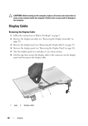
2 Remove the display assembly (see "Removing the Display Assembly" on page 53). 3 Remove the display bezel (see "Removing the Display Bezel" on page 57). 4 Remove the six screws that secure the display panel to the display cover. 5 Note the routing of the display cable and Mini-... holes on the display cover and replace the six screws. 3 Route the display cable through the routing guides on the display cover. 4 Replace the display bezel (see "Replacing the Display Bezel" on page 58). 5 Replace the display assembly (see "Replacing the Display Assembly" on page 56). Display 59
2 Remove the display assembly (see "Removing the Display Assembly" on page 53). 3 Remove the display bezel (see "Removing the Display Bezel" on page 57). 4 Remove the six screws that secure the display panel to the display cover. 5 Note the routing of the display cable and Mini-... holes on the display cover and replace the six screws. 3 Route the display cable through the routing guides on the display cover. 4 Replace the display bezel (see "Replacing the Display Bezel" on page 58). 5 Replace the display assembly (see "Replacing the Display Assembly" on page 56). Display 59
Service Manual
Page 60
... may result in "Before You Begin" on page 9. 2 Remove the display assembly (see "Removing the Display Assembly" on page 53). 3 Remove the display bezel (see "Removing the Display Bezel" on page 57). 4 Remove the display panel (see "Removing the Display Panel" on page 58). 5 Turn the display panel over and place it...
... may result in "Before You Begin" on page 9. 2 Remove the display assembly (see "Removing the Display Assembly" on page 53). 3 Remove the display bezel (see "Removing the Display Bezel" on page 57). 4 Remove the display panel (see "Removing the Display Panel" on page 58). 5 Turn the display panel over and place it...
Service Manual
Page 61
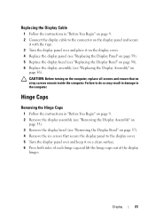
... in "Before You Begin" on page 9. 2 Remove the display assembly (see "Removing the Display Assembly" on page 53). 3 Remove the display bezel (see "Replacing the Display Assembly" on page 56). Failure to do so may result in damage to the display cover. 5 Turn the display panel... Replace the display panel (see "Replacing the Display Panel" on page 59). 5 Replace the display bezel (see "Replacing the Display Bezel" on page 58). 6 Replace the display assembly (see "Removing the Display Bezel" on page 57). 4 Remove the six screws that no stray screws remain inside the computer. CAUTION...
... in "Before You Begin" on page 9. 2 Remove the display assembly (see "Removing the Display Assembly" on page 53). 3 Remove the display bezel (see "Replacing the Display Assembly" on page 56). Failure to do so may result in damage to the display cover. 5 Turn the display panel... Replace the display panel (see "Replacing the Display Panel" on page 59). 5 Replace the display bezel (see "Replacing the Display Bezel" on page 58). 6 Replace the display assembly (see "Removing the Display Bezel" on page 57). 4 Remove the six screws that no stray screws remain inside the computer. CAUTION...
Service Manual
Page 62
... (see "Replacing the Display Assembly" on page 56). Failure to do so may result in damage to the display cover. 5 Replace the display bezel (see "Replacing the Display Bezel" on page 58). 6 Replace the display assembly (see "Removing the Display Assembly" on the computer, replace all screws and ensure that secure the...
... (see "Replacing the Display Assembly" on page 56). Failure to do so may result in damage to the display cover. 5 Replace the display bezel (see "Replacing the Display Bezel" on page 58). 6 Replace the display assembly (see "Removing the Display Assembly" on the computer, replace all screws and ensure that secure the...
Service Manual
Page 63
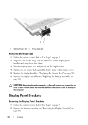
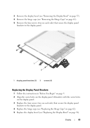
3 Remove the display bezel (see "Removing the Display Bezel" on page 57). 4 Remove the hinge caps (see "Removing the Hinge Caps" on page 61). 5 Remove the four screws (two on each side) that secure ...) that secure the display-panel brackets to the display panel. 4 Replace the hinge caps (see "Replacing the Hinge Caps" on page 62). 5 Replace the display bezel (see "Replacing the Display Bezel" on page 58). Display 63
3 Remove the display bezel (see "Removing the Display Bezel" on page 57). 4 Remove the hinge caps (see "Removing the Hinge Caps" on page 61). 5 Remove the four screws (two on each side) that secure ...) that secure the display-panel brackets to the display panel. 4 Replace the hinge caps (see "Replacing the Hinge Caps" on page 62). 5 Replace the display bezel (see "Replacing the Display Bezel" on page 58). Display 63

Service Manual
Page 65
...cover (see "Removing the Battery" on your computer). Camera Module 65 For additional safety best practices information, see "Removing the Display Bezel" on page 57). 9 Using a plastic scribe, pry the camera module from the connector on your computer. Damage due to servicing... 31). 7 Remove the display assembly (see "Removing the Display Assembly" on page 53). 8 Remove the display bezel (see the Regulatory Compliance Homepage at dell.com/regulatory_compliance. 14 Camera Module WARNING: Before working inside your computer, read the safety information that shipped with your ...
...cover (see "Removing the Battery" on your computer). Camera Module 65 For additional safety best practices information, see "Removing the Display Bezel" on page 57). 9 Using a plastic scribe, pry the camera module from the connector on your computer. Damage due to servicing... 31). 7 Remove the display assembly (see "Removing the Display Assembly" on page 53). 8 Remove the display bezel (see the Regulatory Compliance Homepage at dell.com/regulatory_compliance. 14 Camera Module WARNING: Before working inside your computer, read the safety information that shipped with your ...
Service Manual
Page 66
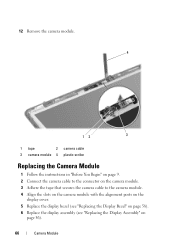
12 Remove the camera module. 4 12 3 1 tape 2 camera cable 3 camera module 4 plastic scribe Replacing the Camera Module 1 Follow the instructions in "Before You Begin" on page 9. 2 Connect the camera cable to the connector on the camera module. 3 Adhere the tape that secures the camera cable to the camera module. 4 Align the slots on the camera module with the alignment posts on the display cover. 5 Replace the display bezel (see "Replacing the Display Bezel" on page 58). 6 Replace the display assembly (see "Replacing the Display Assembly" on page 56). 66 Camera Module
12 Remove the camera module. 4 12 3 1 tape 2 camera cable 3 camera module 4 plastic scribe Replacing the Camera Module 1 Follow the instructions in "Before You Begin" on page 9. 2 Connect the camera cable to the connector on the camera module. 3 Adhere the tape that secures the camera cable to the camera module. 4 Align the slots on the camera module with the alignment posts on the display cover. 5 Replace the display bezel (see "Replacing the Display Bezel" on page 58). 6 Replace the display assembly (see "Replacing the Display Assembly" on page 56). 66 Camera Module

Service Manual
Page 5
... the Thermal Fan 50 13 Display 53 Display Assembly 53 Removing the Display Assembly 53 Replacing the Display Assembly 56 Display Bezel 57 Removing the Display Bezel 57 Replacing the Display Bezel 58 Display Panel 58 Removing the Display Panel 58 Replacing the Display Panel 59 Display Cable 60 Removing the Display Cable...
... the Thermal Fan 50 13 Display 53 Display Assembly 53 Removing the Display Assembly 53 Replacing the Display Assembly 56 Display Bezel 57 Removing the Display Bezel 57 Replacing the Display Bezel 58 Display Panel 58 Removing the Display Panel 58 Replacing the Display Panel 59 Display Cable 60 Removing the Display Cable...
Service Manual
Page 20
2 1 1 optical-drive assembly 2 screw 6 Remove the two screws that secure the optical-drive bracket to the optical drive. 7 Pull the optical-drive bezel to detach it from the optical drive. 20 Optical Drive
2 1 1 optical-drive assembly 2 screw 6 Remove the two screws that secure the optical-drive bracket to the optical drive. 7 Pull the optical-drive bezel to detach it from the optical drive. 20 Optical Drive

Service Manual
Page 21
...so may result in "Before You Begin" on page 9. 2 Align the tabs on the optical-drive bezel with the slots on the optical drive and snap the optical-drive bezel into place. 3 Align the screw holes on the optical-drive bracket with the screw holes on the optical... that no stray screws remain inside the computer. CAUTION: Before turning on page 16). 4 1 2 3 1 screws (2) 3 optical drive 2 optical-drive bracket 4 optical-drive bezel Replacing the Optical Drive 1 Follow the instructions in damage to the computer base. 6 Replace the module cover (see "Replacing the Module Cover" on page 18...
...so may result in "Before You Begin" on page 9. 2 Align the tabs on the optical-drive bezel with the slots on the optical drive and snap the optical-drive bezel into place. 3 Align the screw holes on the optical-drive bracket with the screw holes on the optical... that no stray screws remain inside the computer. CAUTION: Before turning on page 16). 4 1 2 3 1 screws (2) 3 optical drive 2 optical-drive bracket 4 optical-drive bezel Replacing the Optical Drive 1 Follow the instructions in damage to the computer base. 6 Replace the module cover (see "Replacing the Module Cover" on page 18...
Service Manual
Page 57
... your fingertips, carefully pry up the inside the computer. Be careful when removing it to the computer. CAUTION: The display bezel is extremely fragile. Display Bezel Removing the Display Bezel 1 Follow the instructions in "Before You Begin" on page 9. 2 Remove the top cover (see "Removing the Top Cover" on page 13). 3 Remove the... the battery (see "Removing the Display Assembly" on the computer, replace all screws and ensure that no stray screws remain inside edge of the display bezel. 5 Remove the display...
... your fingertips, carefully pry up the inside the computer. Be careful when removing it to the computer. CAUTION: The display bezel is extremely fragile. Display Bezel Removing the Display Bezel 1 Follow the instructions in "Before You Begin" on page 9. 2 Remove the top cover (see "Removing the Top Cover" on page 13). 3 Remove the... the battery (see "Removing the Display Assembly" on the computer, replace all screws and ensure that no stray screws remain inside edge of the display bezel. 5 Remove the display...
Service Manual
Page 58
1 1 display bezel Replacing the Display Bezel 1 Follow the instructions in "Before You Begin" on page 14). Display Panel Removing the Display Panel 1 Follow the instructions in "Before You Begin" on page 9. 2 Realign the display bezel over the display panel and gently snap it into place. 3 Replace the display assembly (see "Replacing the Display Assembly" on page 56). 4 Replace the top cover (see "Replacing the Top Cover" on page 9. 58 Display
1 1 display bezel Replacing the Display Bezel 1 Follow the instructions in "Before You Begin" on page 14). Display Panel Removing the Display Panel 1 Follow the instructions in "Before You Begin" on page 9. 2 Realign the display bezel over the display panel and gently snap it into place. 3 Replace the display assembly (see "Replacing the Display Assembly" on page 56). 4 Replace the top cover (see "Replacing the Top Cover" on page 9. 58 Display

Service Manual
Page 59
Display 59 2 Remove the display assembly (see "Removing the Display Assembly" on page 53). 3 Remove the display bezel (see "Removing the Display Bezel" on page 57). 4 Remove the six screws that secure the display panel to the display cover. 5 Note the routing of the display cable and Mini-... holes on the display cover and replace the six screws. 3 Route the display cable through the routing guides on the display cover. 4 Replace the display bezel (see "Replacing the Display Bezel" on page 58). 5 Replace the display assembly (see "Replacing the Display Assembly" on page 56).
Display 59 2 Remove the display assembly (see "Removing the Display Assembly" on page 53). 3 Remove the display bezel (see "Removing the Display Bezel" on page 57). 4 Remove the six screws that secure the display panel to the display cover. 5 Note the routing of the display cable and Mini-... holes on the display cover and replace the six screws. 3 Route the display cable through the routing guides on the display cover. 4 Replace the display bezel (see "Replacing the Display Bezel" on page 58). 5 Replace the display assembly (see "Replacing the Display Assembly" on page 56).

Service Manual
Page 60
... may result in "Before You Begin" on page 9. 2 Remove the display assembly (see "Removing the Display Assembly" on page 53). 3 Remove the display bezel (see "Removing the Display Bezel" on page 57). 4 Remove the display panel (see "Removing the Display Panel" on page 58). 5 Turn the display panel over and place it...
... may result in "Before You Begin" on page 9. 2 Remove the display assembly (see "Removing the Display Assembly" on page 53). 3 Remove the display bezel (see "Removing the Display Bezel" on page 57). 4 Remove the display panel (see "Removing the Display Panel" on page 58). 5 Turn the display panel over and place it...

Service Manual
Page 61
...4 Replace the display panel (see "Replacing the Display Panel" on page 59). 5 Replace the display bezel (see "Replacing the Display Bezel" on page 58). 6 Replace the display assembly (see "Removing the Display Bezel" on page 56). Replacing the Display Cable 1 Follow the instructions in damage to the computer. Failure ... in "Before You Begin" on page 9. 2 Remove the display assembly (see "Removing the Display Assembly" on page 53). 3 Remove the display bezel (see "Replacing the Display Assembly" on page 57). 4 Remove the six screws that no stray screws remain inside the computer.
...4 Replace the display panel (see "Replacing the Display Panel" on page 59). 5 Replace the display bezel (see "Replacing the Display Bezel" on page 58). 6 Replace the display assembly (see "Removing the Display Bezel" on page 56). Replacing the Display Cable 1 Follow the instructions in damage to the computer. Failure ... in "Before You Begin" on page 9. 2 Remove the display assembly (see "Removing the Display Assembly" on page 53). 3 Remove the display bezel (see "Replacing the Display Assembly" on page 57). 4 Remove the six screws that no stray screws remain inside the computer.


