
View
Page 10
... 139 Removing the Hard Drive 140 Replacing the Hard Drive 141 Returning a Hard Drive to Dell 142 Optical Drive 142 Removing the Optical Drive 142 Replacing the Optical Drive 143 Hinge Cover 143 Removing the Hinge Cover 144 Replacing the Hinge Cover 144 Keyboard 145 Removing the Keyboard 145 Replacing the Keyboard 146 Memory 147 Removing the DIMM...
... 139 Removing the Hard Drive 140 Replacing the Hard Drive 141 Returning a Hard Drive to Dell 142 Optical Drive 142 Removing the Optical Drive 142 Replacing the Optical Drive 143 Hinge Cover 143 Removing the Hinge Cover 144 Replacing the Hinge Cover 144 Keyboard 145 Removing the Keyboard 145 Replacing the Keyboard 146 Memory 147 Removing the DIMM...
View
Page 113
... EXPECTING VALUE - MEMORY WRITE/READ FAILURE AT ADDRESS, READ VALUE EXPECTING VALUE - Reinstall the memory modules and, if necessary, replace them (see "Contacting Dell" on page 147). N O T I M E R T I C K I O N E R R O R - Restart the computer, and avoid touching the keyboard or keys during the boot routine. L I C E N S E D C O N T E N T I S N O T A C C E S S I B L E I N M E D ...FAILURE AT ADDRESS, READ VALUE EXPECTING VALUE - Reinstall the memory modules and, if necessary, replace them (see "Dell Diagnostics" on page 147). A memory module may be corrupted. If the hard drive is...
... EXPECTING VALUE - MEMORY WRITE/READ FAILURE AT ADDRESS, READ VALUE EXPECTING VALUE - Reinstall the memory modules and, if necessary, replace them (see "Contacting Dell" on page 147). N O T I M E R T I C K I O N E R R O R - Restart the computer, and avoid touching the keyboard or keys during the boot routine. L I C E N S E D C O N T E N T I S N O T A C C E S S I B L E I N M E D ...FAILURE AT ADDRESS, READ VALUE EXPECTING VALUE - Reinstall the memory modules and, if necessary, replace them (see "Dell Diagnostics" on page 147). A memory module may be corrupted. If the hard drive is...

View
Page 115
... L E D - Replace the battery, or connect the computer to charge the battery. Double-click the Safely Remove Hardware icon in the Dell Diagnostics (see "Contacting Dell" on page 122. TIME- O F - The keyboard controller may be malfunctioning.... Insert a disk into the connector. IF YOU HAVE PROBLEMS WITH AN EXPRESSCARD NOT PROVIDED BY DELL - P L E A S E R U N T H E S YS T E M S E T U P P R O G R A M - TI M E R C H I P C O U N T E R 2 F A I S N O T R E A D Y - Run the System Memory tests and the Keyboard Controller test in the Windows taskbar. WA R N I N G : B A T T...
... L E D - Replace the battery, or connect the computer to charge the battery. Double-click the Safely Remove Hardware icon in the Dell Diagnostics (see "Contacting Dell" on page 122. TIME- O F - The keyboard controller may be malfunctioning.... Insert a disk into the connector. IF YOU HAVE PROBLEMS WITH AN EXPRESSCARD NOT PROVIDED BY DELL - P L E A S E R U N T H E S YS T E M S E T U P P R O G R A M - TI M E R C H I P C O U N T E R 2 F A I S N O T R E A D Y - Run the System Memory tests and the Keyboard Controller test in the Windows taskbar. WA R N I N G : B A T T...

View
Page 145
...2 Remove the hinge cover (see "Using the Keyboard and Touch Pad" on page 41. Be careful when removing and handling the keyboard. 4 Slide the keyboard toward the back of the computer to replace. NOTICE: The keycaps on the keyboard are fragile, easily dislodged, and timeconsuming to disengage... the notch on the keyboard from the battery bay before you begin working ...
...2 Remove the hinge cover (see "Using the Keyboard and Touch Pad" on page 41. Be careful when removing and handling the keyboard. 4 Slide the keyboard toward the back of the computer to replace. NOTICE: The keycaps on the keyboard are fragile, easily dislodged, and timeconsuming to disengage... the notch on the keyboard from the battery bay before you begin working ...

View
Page 146
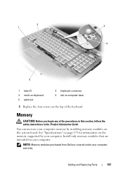
2 1 3 4 1 keyboard 3 notch on keyboard 2 screws (4) 4 tab on computer base Replacing the Keyboard 1 Hook the tabs and the keyboard connector along the front edge of the keyboard into the palmrest, and place the notch on the top of the keyboard on the tab on the base of the computer. 2 Keeping the keyboard flat against the computer base, slide the tabs on the bottom of the keyboard under the palmrest, and ensure the tab on the computer base slides into the notch on the top of the keyboard. 146 Adding and Replacing Parts
2 1 3 4 1 keyboard 3 notch on keyboard 2 screws (4) 4 tab on computer base Replacing the Keyboard 1 Hook the tabs and the keyboard connector along the front edge of the keyboard into the palmrest, and place the notch on the top of the keyboard on the tab on the base of the computer. 2 Keeping the keyboard flat against the computer base, slide the tabs on the bottom of the keyboard under the palmrest, and ensure the tab on the computer base slides into the notch on the top of the keyboard. 146 Adding and Replacing Parts
View
Page 147
... you begin any of the keyboard. See "Specifications" on page 179 for your computer warranty. Install only memory modules that are covered under your computer. NOTE: Memory modules purchased from Dell are intended for information on ...the memory supported by installing memory modules on the top of the procedures in this section, follow the safety instructions in the Product Information Guide. Adding and Replacing Parts 147 2 1 3 4 5 1 tabs (7) 3 notch on keyboard 5 palmrest 2 keyboard connector 4 tab on computer base 3 Replace...
... you begin any of the keyboard. See "Specifications" on page 179 for your computer warranty. Install only memory modules that are covered under your computer. NOTE: Memory modules purchased from Dell are intended for information on ...the memory supported by installing memory modules on the top of the procedures in this section, follow the safety instructions in the Product Information Guide. Adding and Replacing Parts 147 2 1 3 4 5 1 tabs (7) 3 notch on keyboard 5 palmrest 2 keyboard connector 4 tab on computer base 3 Replace...

View
Page 148
... before you install a module in the connector labeled "DIMMA." The DIMM A memory module is located under the keyboard. 1 Follow the procedures in "Before You Begin" on page 137. 2 Remove the hinge cover (see "Hinge Cover" on... page 143). 3 Remove the keyboard (see "Keyboard" on each end of the memory module connector until the module pops up. 5 Remove the module from the... clips. 4 Use your computer has only one accessed from beneath the keyboard (DIMM A), and the other accessed from the connector. 148 Adding and Replacing Parts
... before you install a module in the connector labeled "DIMMA." The DIMM A memory module is located under the keyboard. 1 Follow the procedures in "Before You Begin" on page 137. 2 Remove the hinge cover (see "Hinge Cover" on... page 143). 3 Remove the keyboard (see "Keyboard" on each end of the memory module connector until the module pops up. 5 Remove the module from the... clips. 4 Use your computer has only one accessed from beneath the keyboard (DIMM A), and the other accessed from the connector. 148 Adding and Replacing Parts

View
Page 150
To confirm the amount of the computer. 1 Follow the procedures in the computer, click Start →Help and Support→Dell System Information. Removing the DIMM B Memory Module The DIMM B memory module is located under the memory module cover on the bottom of memory installed.... 2 Turn the computer upside-down, loosen the captive screw on the memory module cover (see "Bottom View" on the computer. 1 2 1 tab 2 notch 3 Replace the keyboard and hinge cover. 4 Insert the battery into the battery bay, or connect the AC adapter to your computer and an electrical outlet. 5 Turn on page...
To confirm the amount of the computer. 1 Follow the procedures in the computer, click Start →Help and Support→Dell System Information. Removing the DIMM B Memory Module The DIMM B memory module is located under the memory module cover on the bottom of memory installed.... 2 Turn the computer upside-down, loosen the captive screw on the memory module cover (see "Bottom View" on the computer. 1 2 1 tab 2 notch 3 Replace the keyboard and hinge cover. 4 Insert the battery into the battery bay, or connect the AC adapter to your computer and an electrical outlet. 5 Turn on page...
View
Page 213
...enabling, 78 audio. See sound B battery charge gauge, 49 charging, 51 checking the charge, 48 performance, 47 power meter, 49 removing, 52 replacing coin-cell battery, 165 storing, 53 BD. See Blu-ray Disc blanks ExpressCards, 79, 83 removing, 81, 84 Bluetooth wireless technology card device ... 170 CD about, 58 CD-RW drive problems, 107 drive problems, 107 Check Disk, 108 cleaning display, 190 keyboard, 190 media, 192 mouse, 191 touch pad, 191 coin-cell battery replacing, 165 computer crashes, 118-119 restore to previous operating state, 134 slow performance, 110, 120 specifications, 179 stops...
...enabling, 78 audio. See sound B battery charge gauge, 49 charging, 51 checking the charge, 48 performance, 47 power meter, 49 removing, 52 replacing coin-cell battery, 165 storing, 53 BD. See Blu-ray Disc blanks ExpressCards, 79, 83 removing, 81, 84 Bluetooth wireless technology card device ... 170 CD about, 58 CD-RW drive problems, 107 drive problems, 107 Check Disk, 108 cleaning display, 190 keyboard, 190 media, 192 mouse, 191 touch pad, 191 coin-cell battery replacing, 165 computer crashes, 118-119 restore to previous operating state, 134 slow performance, 110, 120 specifications, 179 stops...

View
Page 215
... Cache Module Flash Cache Module, 162 H hard drive description, 27, 34 problems, 108 replacing, 139 returning to Dell, 142 hardware Dell Diagnostics, 99 Hardware Troubleshooter, 132 hinge cover removing, 143 K keyboard numeric keypad, 41 problems, 116 removing, 145 shortcuts, 41 keyboard status lights description, 26 keypad numeric, 41 L labels Microsoft Windows, 16 Service Tag, 16...
... Cache Module Flash Cache Module, 162 H hard drive description, 27, 34 problems, 108 replacing, 139 returning to Dell, 142 hardware Dell Diagnostics, 99 Hardware Troubleshooter, 132 hinge cover removing, 143 K keyboard numeric keypad, 41 problems, 116 removing, 145 shortcuts, 41 keyboard status lights description, 26 keypad numeric, 41 L labels Microsoft Windows, 16 Service Tag, 16...

Service Manual
Page 3
... procedure, follow the safety instructions in the Product Information Guide. 1. Remove the display assembly (see Replacing the Keyboard). 8. Lift the audio connector board out of the computer. 10. NOTICE: Do not disconnect the audio cable...from the audio connector board. Replace the keyboard (see Removing the Display Assembly). 7. Remove the keyboard (see Replacing the Hinge Cover). 9. Replace the hinge cover (see Removing the Keyboard). 6. Replace the hard drive (see Replacing the Palm Rest). 5. Replace the palm rest (see Replacing a Hard Drive). 10. Remove...
... procedure, follow the safety instructions in the Product Information Guide. 1. Remove the display assembly (see Replacing the Keyboard). 8. Lift the audio connector board out of the computer. 10. NOTICE: Do not disconnect the audio cable...from the audio connector board. Replace the keyboard (see Removing the Display Assembly). 7. Remove the keyboard (see Replacing the Hinge Cover). 9. Replace the hinge cover (see Removing the Keyboard). 6. Replace the hard drive (see Replacing the Palm Rest). 5. Replace the palm rest (see Replacing a Hard Drive). 10. Remove...

Service Manual
Page 4
... to the base of the computer, and then lower the board into place. 3. Replace the keyboard (see Replacing the Optical Drive). Replace the optical drive (see Replacing the Keyboard). 8. Remove the keyboard (see Removing the Display Assembly). 7. Remove the display assembly (see Removing the Keyboard). 6. Replace the M2.5 x 5-mm screw and secure the audio connector board to the audio...
... to the base of the computer, and then lower the board into place. 3. Replace the keyboard (see Replacing the Optical Drive). Replace the optical drive (see Replacing the Keyboard). 8. Remove the keyboard (see Removing the Display Assembly). 7. Remove the display assembly (see Removing the Keyboard). 6. Replace the M2.5 x 5-mm screw and secure the audio connector board to the audio...

Service Manual
Page 5
...Align the screw hole in the CIR board with Bluetooth wireless technology, if installed (see Removing the Palm Rest). 9. Replace the hard drive (see Replacing the Hinge Cover). 9. NOTICE: Do not disconnect the CIR cable from the CIR board. Connect the CIR cable to... 10. Replace the palm rest (see Replacing the Display Assembly). 7. Remove the M2.5 x 5-mm screw that secures the CIR board to the CIR board. 2. Replace the optical drive (see Removing the Optical Drive). Remove the optical drive (see Replacing the Optical Drive). Replace the keyboard (see Replacing the Keyboard). 8.
...Align the screw hole in the CIR board with Bluetooth wireless technology, if installed (see Removing the Palm Rest). 9. Replace the hard drive (see Replacing the Hinge Cover). 9. NOTICE: Do not disconnect the CIR cable from the CIR board. Connect the CIR cable to... 10. Replace the palm rest (see Replacing the Display Assembly). 7. Remove the M2.5 x 5-mm screw that secures the CIR board to the CIR board. 2. Replace the optical drive (see Removing the Optical Drive). Remove the optical drive (see Replacing the Optical Drive). Replace the keyboard (see Replacing the Keyboard). 8.

Service Manual
Page 6
... the internal card with Bluetooth wireless technology, if installed (see Replacing the Bluetooth Card). 6. Remove the keyboard (see Replacing the Optical Drive). Replace the optical drive (see Removing the Keyboard). 6. Remove the hard drive (see Replacing the Palm Rest). 5. Replace the palm rest (see Removing a Hard Drive). 4. Replace the display assembly (see Removing the Bluetooth Card). 8. Disconnect the...
... the internal card with Bluetooth wireless technology, if installed (see Replacing the Bluetooth Card). 6. Remove the keyboard (see Replacing the Optical Drive). Replace the optical drive (see Removing the Keyboard). 6. Remove the hard drive (see Replacing the Palm Rest). 5. Replace the palm rest (see Removing a Hard Drive). 4. Replace the display assembly (see Removing the Bluetooth Card). 8. Disconnect the...

Service Manual
Page 8
...). 7. Remove the display assembly (see Removing a Hard Drive). 4. Replace the hinge cover (see Removing the Keyboard). 6. Remove the keyboard (see Replacing the Hinge Cover). 8. Carefully lift the ExpressCard cage out of the computer. 3. Replace the palm rest (see Replacing the Keyboard). 7. Replace the keyboard (see Replacing the Palm Rest). 4. Computer Base Replace the internal card with the screw holes on the...
...). 7. Remove the display assembly (see Removing a Hard Drive). 4. Replace the hinge cover (see Removing the Keyboard). 6. Remove the keyboard (see Replacing the Hinge Cover). 8. Carefully lift the ExpressCard cage out of the computer. 3. Replace the palm rest (see Replacing the Keyboard). 7. Replace the keyboard (see Replacing the Palm Rest). 4. Computer Base Replace the internal card with the screw holes on the...
Service Manual
Page 19
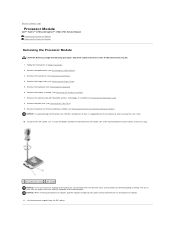
...see Removing the Palm Rest). 9. Remove the palm rest (see Removing the Bluetooth Card). 8. Remove the hinge cover (see Removing the Keyboard). 6. Remove the keyboard (see Removing the Hinge Cover). 5. The oils in Before You Begin. 2. Be careful not to the cam stop. 1 ZIF-... ZIF-socket cam screw counterclockwise until it is perpendicular to Contents Page Processor Module Dell™ Vostro™ 1700 and Inspiron™ 1720/1721 Service Manual Removing the Processor Module Replacing the Processor Module Removing the Processor Module CAUTION: Before you begin the following procedure...
...see Removing the Palm Rest). 9. Remove the palm rest (see Removing the Bluetooth Card). 8. Remove the hinge cover (see Removing the Keyboard). 6. Remove the keyboard (see Removing the Hinge Cover). 5. The oils in Before You Begin. 2. Be careful not to the cam stop. 1 ZIF-... ZIF-socket cam screw counterclockwise until it is perpendicular to Contents Page Processor Module Dell™ Vostro™ 1700 and Inspiron™ 1720/1721 Service Manual Removing the Processor Module Replacing the Processor Module Removing the Processor Module CAUTION: Before you begin the following procedure...

Service Manual
Page 20
...of the module are aligned at the same height. Replace the internal card with the pin-1 corner of the processor module with Bluetooth wireless technology, if installed (see Replacing the Keyboard). 8. Replace the optical drive (see Replacing a Hard Drive). 10. Align the pin-1 corner... of the ZIF socket, then insert the processor module. Replace the hard drive (see Replacing the Optical Drive). A processor module that...
...of the module are aligned at the same height. Replace the internal card with the pin-1 corner of the processor module with Bluetooth wireless technology, if installed (see Replacing the Keyboard). 8. Replace the optical drive (see Replacing a Hard Drive). 10. Align the pin-1 corner... of the ZIF socket, then insert the processor module. Replace the hard drive (see Replacing the Optical Drive). A processor module that...
Service Manual
Page 22
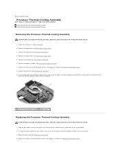
...with Bluetooth wireless technology, if installed (see Removing the Palm Rest). 9. Replace the palm rest (see Removing the Keyboard). 6. Follow the instructions in Before You Begin. 2. Remove the keyboard (see Replacing the Palm Rest). 4. Remove the optical drive (see Removing a Hard... Display Assembly). 7. Back to Contents Page Processor Thermal-Cooling Assembly Dell™ Vostro™ 1700 and Inspiron™ 1720/1721 Service Manual Removing the Processor Thermal-Cooling Assembly Replacing the Processor Thermal-Cooling Assembly Removing the Processor Thermal-Cooling Assembly CAUTION...
...with Bluetooth wireless technology, if installed (see Removing the Palm Rest). 9. Replace the palm rest (see Removing the Keyboard). 6. Follow the instructions in Before You Begin. 2. Remove the keyboard (see Replacing the Palm Rest). 4. Remove the optical drive (see Removing a Hard... Display Assembly). 7. Back to Contents Page Processor Thermal-Cooling Assembly Dell™ Vostro™ 1700 and Inspiron™ 1720/1721 Service Manual Removing the Processor Thermal-Cooling Assembly Replacing the Processor Thermal-Cooling Assembly Removing the Processor Thermal-Cooling Assembly CAUTION...

Service Manual
Page 23
Replace the hinge cover (see Replacing the Optical Drive). Replace the optical drive (see Replacing the Hinge Cover). 8. Back to Contents Page 5. Replace the keyboard (see Replacing a Hard Drive). 9. Replace the hard drive (see Replacing the Keyboard). 7. Replace the display assembly (see Replacing the Display Assembly). 6.
Replace the hinge cover (see Replacing the Optical Drive). Replace the optical drive (see Replacing the Hinge Cover). 8. Back to Contents Page 5. Replace the keyboard (see Replacing a Hard Drive). 9. Replace the hard drive (see Replacing the Keyboard). 7. Replace the display assembly (see Replacing the Display Assembly). 6.

Service Manual
Page 25
Disconnect the camera/microphone cable from the camera/microphone cable connector on the palm rest. 12. Replace the hinge cover (see Replacing the Keyboard). 9. NOTICE: Ensure that the display cable and antenna cables are properly routed and secured beneath the plastic tabs on.... Lift the display assembly out of the computer. 1 display assembly 2 camera/microphone cable 3 antenna cables 4 display cable 5 grounding screw Replacing the Display Assembly CAUTION: Before you begin the following procedure, follow the safety instructions in the base of the computer, then lower the display...
Disconnect the camera/microphone cable from the camera/microphone cable connector on the palm rest. 12. Replace the hinge cover (see Replacing the Keyboard). 9. NOTICE: Ensure that the display cable and antenna cables are properly routed and secured beneath the plastic tabs on.... Lift the display assembly out of the computer. 1 display assembly 2 camera/microphone cable 3 antenna cables 4 display cable 5 grounding screw Replacing the Display Assembly CAUTION: Before you begin the following procedure, follow the safety instructions in the base of the computer, then lower the display...


