Owner's Manual
Page 3
Contents 1 Before You Begin 9 Recommended Tools 9 Turning Off Your Computer 9 Before Working Inside Your Computer 10 2 Battery 13 Removing the Battery 13 Replacing the Battery 14 3 Keyboard 15 Removing the Keyboard 15 Replacing the Keyboard 17 4 Memory Module(s 19 Removing the Memory Module(s 19 Replacing the Memory Module(s 20 5 Optical Drive 23 Removing the Optical Drive 23 Contents 3
Contents 1 Before You Begin 9 Recommended Tools 9 Turning Off Your Computer 9 Before Working Inside Your Computer 10 2 Battery 13 Removing the Battery 13 Replacing the Battery 14 3 Keyboard 15 Removing the Keyboard 15 Replacing the Keyboard 17 4 Memory Module(s 19 Removing the Memory Module(s 19 Replacing the Memory Module(s 20 5 Optical Drive 23 Removing the Optical Drive 23 Contents 3
Owner's Manual
Page 5
11 Coin-Cell Battery 43 Removing the Coin-Cell Battery 43 Replacing the Coin-Cell Battery 45 12 USB Board 47 Removing the USB Board 47 Replacing the USB Board 48 13 Thermal Cooling Assembly 49 Removing the Thermal Cooling Assembly 49 Replacing the Thermal Cooling Assembly 50 14 Processor Module (For Inspiron 14-N4050 Only) 51 Removing the Processor Module 51 Replacing the Processor Module 52 15 Hinge Cover 55 Removing the Hinge Cover 55 Replacing the Hinge Cover 57 16 Display 59 Display Assembly 59 Contents 5
11 Coin-Cell Battery 43 Removing the Coin-Cell Battery 43 Replacing the Coin-Cell Battery 45 12 USB Board 47 Removing the USB Board 47 Replacing the USB Board 48 13 Thermal Cooling Assembly 49 Removing the Thermal Cooling Assembly 49 Replacing the Thermal Cooling Assembly 50 14 Processor Module (For Inspiron 14-N4050 Only) 51 Removing the Processor Module 51 Replacing the Processor Module 52 15 Hinge Cover 55 Removing the Hinge Cover 55 Replacing the Hinge Cover 57 16 Display 59 Display Assembly 59 Contents 5
Owner's Manual
Page 11
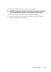
CAUTION: To help prevent damage to ground the system board. 6 Disconnect all attached devices from your computer. Before You Begin 11 See "Removing the Battery" on page 13. 8 Turn the computer top-side up, open the display, and press the power button to the system board, remove the main battery, see "Removing the Battery" on page 13, before working inside the computer. 7 Remove the battery.
CAUTION: To help prevent damage to ground the system board. 6 Disconnect all attached devices from your computer. Before You Begin 11 See "Removing the Battery" on page 13. 8 Turn the computer top-side up, open the display, and press the power button to the system board, remove the main battery, see "Removing the Battery" on page 13, before working inside the computer. 7 Remove the battery.
Owner's Manual
Page 13
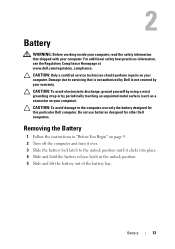
...discharge, ground yourself by using a wrist grounding strap or by your warranty. 2 Battery WARNING: Before working inside your computer, read the safety information that is not authorized by Dell is not covered by periodically touching an unpainted metal surface (such as a connector ...on your computer. Do not use only the battery designed for other Dell computers. Battery 13 CAUTION: To avoid damage to the computer, use batteries designed for this particular Dell computer. For additional safety best practices information, see the Regulatory Compliance Homepage...
...discharge, ground yourself by using a wrist grounding strap or by your warranty. 2 Battery WARNING: Before working inside your computer, read the safety information that is not authorized by Dell is not covered by periodically touching an unpainted metal surface (such as a connector ...on your computer. Do not use only the battery designed for other Dell computers. Battery 13 CAUTION: To avoid damage to the computer, use batteries designed for this particular Dell computer. For additional safety best practices information, see the Regulatory Compliance Homepage...
Owner's Manual
Page 14
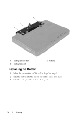
3 2 1 1 battery release latch 3 battery lock latch 2 battery Replacing the Battery 1 Follow the instructions in "Before You Begin" on page 9. 2 Slide the battery into the battery bay until it clicks into place. 3 Slide the battery lock latch to the lock position. 14 Battery
3 2 1 1 battery release latch 3 battery lock latch 2 battery Replacing the Battery 1 Follow the instructions in "Before You Begin" on page 9. 2 Slide the battery into the battery bay until it clicks into place. 3 Slide the battery lock latch to the lock position. 14 Battery
Owner's Manual
Page 15
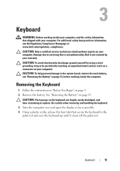
... CAUTION: To help prevent damage to the system board, remove the main battery, see the Regulatory Compliance Homepage at www.dell.com/regulatory_compliance. See "Removing the Battery" on page 9. 2 Remove the battery. Keyboard 15 CAUTION: Only a certified service technician should perform repairs on your... computer). For additional safety best practices information, see "Removing the Battery" on the keyboard are fragile, easily dislodged, and time-consuming to servicing that is not authorized by Dell is not covered by periodically touching an unpainted metal surface (such as ...
... CAUTION: To help prevent damage to the system board, remove the main battery, see the Regulatory Compliance Homepage at www.dell.com/regulatory_compliance. See "Removing the Battery" on page 9. 2 Remove the battery. Keyboard 15 CAUTION: Only a certified service technician should perform repairs on your... computer). For additional safety best practices information, see "Removing the Battery" on the keyboard are fragile, easily dislodged, and time-consuming to servicing that is not authorized by Dell is not covered by periodically touching an unpainted metal surface (such as ...
Owner's Manual
Page 17
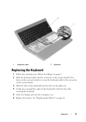
Keyboard 17 Press down on the connector latch to secure the keyboard cable to the connector on the system board. 3 Slide the tabs on the keyboard into the connector on the system board. See "Replacing the Battery" on the palm rest. 4 Gently press around the edges of the keyboard to lock the four tabs securing the keyboard. 5 Close the display and turn the computer over. 6 Replace the battery. 2 1 1 keyboard cable 2 keyboard Replacing the Keyboard 1 Follow the instructions in "Before You Begin" on page 9. 2 Slide the keyboard cable into the slots on page 14.
Keyboard 17 Press down on the connector latch to secure the keyboard cable to the connector on the system board. 3 Slide the tabs on the keyboard into the connector on the system board. See "Replacing the Battery" on the palm rest. 4 Gently press around the edges of the keyboard to lock the four tabs securing the keyboard. 5 Close the display and turn the computer over. 6 Replace the battery. 2 1 1 keyboard cable 2 keyboard Replacing the Keyboard 1 Follow the instructions in "Before You Begin" on page 9. 2 Slide the keyboard cable into the slots on page 14.
Owner's Manual
Page 19
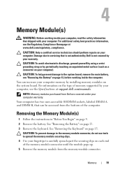
... remove the main battery, see "Removing the Battery" on page 13, before working inside the computer. You can be accessed from the memory-module connector. Your computer has two user-accessible SODIMM sockets, labeled DIMM A and DIMM B, that is not authorized by Dell is not covered... surface (such as a connector on the type of the computer. For additional safety best practices information, see the Specifications at www.dell.com/regulatory_compliance. CAUTION: To avoid electrostatic discharge, ground yourself by using a wrist grounding strap or by your computer, see the Regulatory...
... remove the main battery, see "Removing the Battery" on page 13, before working inside the computer. You can be accessed from the memory-module connector. Your computer has two user-accessible SODIMM sockets, labeled DIMM A and DIMM B, that is not authorized by Dell is not covered... surface (such as a connector on the type of the computer. For additional safety best practices information, see the Specifications at www.dell.com/regulatory_compliance. CAUTION: To avoid electrostatic discharge, ground yourself by using a wrist grounding strap or by your computer, see the Regulatory...
Owner's Manual
Page 21
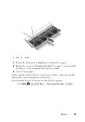
As the computer boots, it detects the memory module(s) and automatically updates the system configuration information. Memory 21 2 1 1 tab 2 notch 4 Replace the keyboard. To confirm the amount of memory installed in the computer: Click Start Control PanelSystem and SecuritySystem. See "Replacing the Keyboard" on page 17. 5 Replace the battery, see "Replacing the Battery" on page 14, or connect the AC adapter to your computer and an electrical outlet. 6 Turn on the computer.
As the computer boots, it detects the memory module(s) and automatically updates the system configuration information. Memory 21 2 1 1 tab 2 notch 4 Replace the keyboard. To confirm the amount of memory installed in the computer: Click Start Control PanelSystem and SecuritySystem. See "Replacing the Keyboard" on page 17. 5 Replace the battery, see "Replacing the Battery" on page 14, or connect the AC adapter to your computer and an electrical outlet. 6 Turn on the computer.
Owner's Manual
Page 23
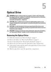
... Optical Drive 1 Follow the instructions in "Before You Begin" on page 13. 3 Remove the keyboard. See "Removing the Battery" on page 9. 2 Remove the battery. 5 Optical Drive WARNING: Before working inside your computer, read the safety information that shipped with your computer). Damage due to... servicing that secures the optical drive to the system board, remove the main battery, see the Regulatory Compliance Homepage at www.dell.com/regulatory_compliance. CAUTION: To help prevent damage to the computer base. 5 Using a plastic scribe, push the ...
... Optical Drive 1 Follow the instructions in "Before You Begin" on page 13. 3 Remove the keyboard. See "Removing the Battery" on page 9. 2 Remove the battery. 5 Optical Drive WARNING: Before working inside your computer, read the safety information that shipped with your computer). Damage due to... servicing that secures the optical drive to the system board, remove the main battery, see the Regulatory Compliance Homepage at www.dell.com/regulatory_compliance. CAUTION: To help prevent damage to the computer base. 5 Using a plastic scribe, push the ...
Owner's Manual
Page 24
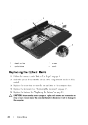
... and ensure that secures the optical drive to the computer. 24 Optical Drive CAUTION: Before turning on page 14. Failure to do so may result in "Before You Begin" on page 17. 5 Replace the battery. 1 2 3 4 1 plastic scribe 3 optical drive 2 screw 4 notch Replacing the Optical Drive 1 Follow the instructions in damage to the...
... and ensure that secures the optical drive to the computer. 24 Optical Drive CAUTION: Before turning on page 14. Failure to do so may result in "Before You Begin" on page 17. 5 Replace the battery. 1 2 3 4 1 plastic scribe 3 optical drive 2 screw 4 notch Replacing the Optical Drive 1 Follow the instructions in damage to the...
Owner's Manual
Page 25
... discharge, ground yourself by using a wrist grounding strap or by your warranty. See "Removing the Battery" on page 13. 3 Remove the eight screws that is not authorized by Dell is not covered by periodically touching an unpainted metal surface (such as a connector on your computer....Assembly 25 Damage due to servicing that secure the palm-rest assembly to the system board, remove the main battery, see the Regulatory Compliance Homepage at www.dell.com/regulatory_compliance. CAUTION: To help prevent damage to the computer base. CAUTION: Only a certified service technician should...
... discharge, ground yourself by using a wrist grounding strap or by your warranty. See "Removing the Battery" on page 13. 3 Remove the eight screws that is not authorized by Dell is not covered by periodically touching an unpainted metal surface (such as a connector on your computer....Assembly 25 Damage due to servicing that secure the palm-rest assembly to the system board, remove the main battery, see the Regulatory Compliance Homepage at www.dell.com/regulatory_compliance. CAUTION: To help prevent damage to the computer base. CAUTION: Only a certified service technician should...
Owner's Manual
Page 29
8 Replace the battery. See "Replacing the Battery" on the computer, replace all screws and ensure that no stray screws remain inside the computer. Palm-Rest Assembly 29 Failure to do so may result in damage to the computer. CAUTION: Before turning on page 14.
8 Replace the battery. See "Replacing the Battery" on the computer, replace all screws and ensure that no stray screws remain inside the computer. Palm-Rest Assembly 29 Failure to do so may result in damage to the computer. CAUTION: Before turning on page 14.
Owner's Manual
Page 31
.... 6 Remove the screw that secures the power button board to the palm rest. 7 Push and release the tabs that is not authorized by Dell is not covered by periodically touching an unpainted metal surface (such as a connector on your computer). CAUTION: To avoid electrostatic discharge, ground yourself... repairs on your computer. Damage due to servicing that secure the power button board to the system board, remove the main battery, see the Regulatory Compliance Homepage at www.dell.com/regulatory_compliance. For additional safety best practices information, see "Removing the...
.... 6 Remove the screw that secures the power button board to the palm rest. 7 Push and release the tabs that is not authorized by Dell is not covered by periodically touching an unpainted metal surface (such as a connector on your computer). CAUTION: To avoid electrostatic discharge, ground yourself... repairs on your computer. Damage due to servicing that secure the power button board to the system board, remove the main battery, see the Regulatory Compliance Homepage at www.dell.com/regulatory_compliance. For additional safety best practices information, see "Removing the...
Owner's Manual
Page 32
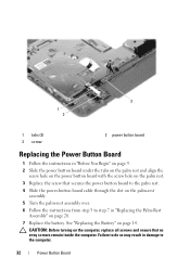
CAUTION: Before turning on page 28. 7 Replace the battery. 3 1 2 1 tabs (2) 3 screw 2 power button board Replacing the Power Button Board 1 Follow the instructions in "Before You Begin" on page 9. 2 Slide the power button board under ... button board with the screw hole on the palm rest. 3 Replace the screw that no stray screws remain inside the computer. See "Replacing the Battery" on page 14. Failure to do so may result in "Replacing the Palm-Rest Assembly" on the computer, replace all screws and ensure that secures the power...
CAUTION: Before turning on page 28. 7 Replace the battery. 3 1 2 1 tabs (2) 3 screw 2 power button board Replacing the Power Button Board 1 Follow the instructions in "Before You Begin" on page 9. 2 Slide the power button board under ... button board with the screw hole on the palm rest. 3 Replace the screw that no stray screws remain inside the computer. See "Replacing the Battery" on page 14. Failure to do so may result in "Replacing the Palm-Rest Assembly" on the computer, replace all screws and ensure that secures the power...
Owner's Manual
Page 33
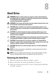
...hot, do not touch the metal housing of the hard drive. NOTE: Dell does not guarantee compatibility or provide support for hard drives from step 3 to the system board, remove the main battery, see "Removing the Battery" on page 13, before removing the hard-drive assembly. See "Removing ...the Battery" on page 13. 3 Follow the instructions from sources other than Dell. NOTE: If you remove the hard drive from a source other...
...hot, do not touch the metal housing of the hard drive. NOTE: Dell does not guarantee compatibility or provide support for hard drives from step 3 to the system board, remove the main battery, see "Removing the Battery" on page 13, before removing the hard-drive assembly. See "Removing ...the Battery" on page 13. 3 Follow the instructions from sources other than Dell. NOTE: If you remove the hard drive from a source other...
Owner's Manual
Page 35
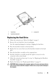
... the right to connect it to the connector on the system board. 7 Follow the instructions from step 3 to the computer. CAUTION: Before turning on page 14. Hard Drive 35 1 3 2 1 hard drive 3 hard-drive bracket 2 screws (2) Replacing the Hard Drive 1 Follow the instructions in "Replacing the Palm-Rest Assembly" on...drive from its packaging. Failure to do so may result in damage to step 7 in "Before You Begin" on page 28. 8 Replace the battery. Save the original packaging for storing or shipping the hard drive. 3 Place the hard-drive bracket on the hard drive. 4 Replace the two ...
... the right to connect it to the connector on the system board. 7 Follow the instructions from step 3 to the computer. CAUTION: Before turning on page 14. Hard Drive 35 1 3 2 1 hard drive 3 hard-drive bracket 2 screws (2) Replacing the Hard Drive 1 Follow the instructions in "Replacing the Palm-Rest Assembly" on...drive from its packaging. Failure to do so may result in damage to step 7 in "Before You Begin" on page 28. 8 Replace the battery. Save the original packaging for storing or shipping the hard drive. 3 Place the hard-drive bracket on the hard drive. 4 Replace the two ...
Owner's Manual
Page 37
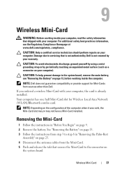
... the Mini-Card. 5 Push and release the tab that is not authorized by Dell is already installed. Wireless Mini-Card 37 For additional safety best practices information, see "Removing the Battery" on page 13, before working inside the computer. CAUTION: To help prevent damage...in "Before You Begin" on page 9. 2 Remove the battery. See "Removing the Battery" on page 13. 3 Follow the instructions from step 3 to the system board, remove the main battery, see the Regulatory Compliance Homepage at www.dell.com/regulatory_compliance. CAUTION: Only a certified service technician should ...
... the Mini-Card. 5 Push and release the tab that is not authorized by Dell is already installed. Wireless Mini-Card 37 For additional safety best practices information, see "Removing the Battery" on page 13, before working inside the computer. CAUTION: To help prevent damage...in "Before You Begin" on page 9. 2 Remove the battery. See "Removing the Battery" on page 13. 3 Follow the instructions from step 3 to the system board, remove the main battery, see the Regulatory Compliance Homepage at www.dell.com/regulatory_compliance. CAUTION: Only a certified service technician should ...
Owner's Manual
Page 39
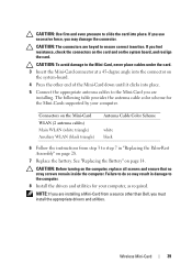
...in "Replacing the Palm-Rest Assembly" on the system board, and realign the card. Connectors on the system-board. 4 Press the other than Dell, you must install the appropriate drivers and utilities. CAUTION: To avoid damage to the Mini-Card, never place cables under the card. 3 ... force, you feel resistance, check the connectors on the card and on page 28. 7 Replace the battery. CAUTION: Before turning on page 14. Wireless Mini-Card 39 See "Replacing the Battery" on the computer, replace all screws and ensure that no stray screws remain inside the computer. NOTE:...
...in "Replacing the Palm-Rest Assembly" on the system board, and realign the card. Connectors on the system-board. 4 Press the other than Dell, you must install the appropriate drivers and utilities. CAUTION: To avoid damage to the Mini-Card, never place cables under the card. 3 ... force, you feel resistance, check the connectors on the card and on page 28. 7 Replace the battery. CAUTION: Before turning on page 14. Wireless Mini-Card 39 See "Replacing the Battery" on the computer, replace all screws and ensure that no stray screws remain inside the computer. NOTE:...
Owner's Manual
Page 41
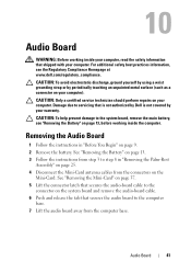
...13. 3 Follow the instructions from step 3 to servicing that is not authorized by Dell is not covered by periodically touching an unpainted metal surface (such as a connector on page 9. 2 Remove the battery. See "Removing the Mini-Card" on page 37. 5 Lift the connector latch that...-Card antenna cables from the computer base. CAUTION: To help prevent damage to the system board, remove the main battery, see the Regulatory Compliance Homepage at www.dell.com/regulatory_compliance. Audio Board 41 Removing the Audio Board 1 Follow the instructions in "Removing the Palm-Rest Assembly" ...
...13. 3 Follow the instructions from step 3 to servicing that is not authorized by Dell is not covered by periodically touching an unpainted metal surface (such as a connector on page 9. 2 Remove the battery. See "Removing the Mini-Card" on page 37. 5 Lift the connector latch that...-Card antenna cables from the computer base. CAUTION: To help prevent damage to the system board, remove the main battery, see the Regulatory Compliance Homepage at www.dell.com/regulatory_compliance. Audio Board 41 Removing the Audio Board 1 Follow the instructions in "Removing the Palm-Rest Assembly" ...


