Owner's Manual
Page 1
Dell Inspiron M4040/14-N4050 Owner's Manual Regulatory model: P22G Regulatory type: P22G001; P22G002
Dell Inspiron M4040/14-N4050 Owner's Manual Regulatory model: P22G Regulatory type: P22G001; P22G002
Owner's Manual
Page 5
11 Coin-Cell Battery 43 Removing the Coin-Cell Battery 43 Replacing the Coin-Cell Battery 45 12 USB Board 47 Removing the USB Board 47 Replacing the USB Board 48 13 Thermal Cooling Assembly 49 Removing the Thermal Cooling Assembly 49 Replacing the Thermal Cooling Assembly 50 14 Processor Module (For Inspiron 14-N4050 Only) 51 Removing the Processor Module 51 Replacing the Processor Module 52 15 Hinge Cover 55 Removing the Hinge Cover 55 Replacing the Hinge Cover 57 16 Display 59 Display Assembly 59 Contents 5
11 Coin-Cell Battery 43 Removing the Coin-Cell Battery 43 Replacing the Coin-Cell Battery 45 12 USB Board 47 Removing the USB Board 47 Replacing the USB Board 48 13 Thermal Cooling Assembly 49 Removing the Thermal Cooling Assembly 49 Replacing the Thermal Cooling Assembly 50 14 Processor Module (For Inspiron 14-N4050 Only) 51 Removing the Processor Module 51 Replacing the Processor Module 52 15 Hinge Cover 55 Removing the Hinge Cover 55 Replacing the Hinge Cover 57 16 Display 59 Display Assembly 59 Contents 5
Owner's Manual
Page 43
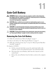
.../regulatory_compliance. For additional safety best practices information, see "Removing the Battery" on your computer. Coin-Cell Battery 43 For Inspiron 14-N4050: a Lift the connector latch that is not authorized by Dell is not covered by periodically touching an unpainted metal surface (such as a connector on page 13, before working inside the computer. CAUTION...
.../regulatory_compliance. For additional safety best practices information, see "Removing the Battery" on your computer. Coin-Cell Battery 43 For Inspiron 14-N4050: a Lift the connector latch that is not authorized by Dell is not covered by periodically touching an unpainted metal surface (such as a connector on page 13, before working inside the computer. CAUTION...
Owner's Manual
Page 45
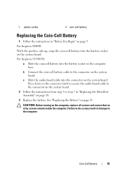
...connector on the system board. 2 Follow the instructions from step 3 to step 7 in damage to the computer. CAUTION: Before turning on page 14. See "Replacing the Battery" on the computer, replace all screws and ensure that no stray screws remain inside the computer. Failure to the ... the battery. b Connect the coin-cell battery cable to do so may result in "Replacing the Palm-Rest Assembly" on the system board. For Inspiron 14-N4050: a Slide the coin-cell battery into the connector on the system board. 1 plastic scribe 2 coin-cell battery Replacing the Coin-Cell Battery 1 ...
...connector on the system board. 2 Follow the instructions from step 3 to step 7 in damage to the computer. CAUTION: Before turning on page 14. See "Replacing the Battery" on the computer, replace all screws and ensure that no stray screws remain inside the computer. Failure to the ... the battery. b Connect the coin-cell battery cable to do so may result in "Replacing the Palm-Rest Assembly" on the system board. For Inspiron 14-N4050: a Slide the coin-cell battery into the connector on the system board. 1 plastic scribe 2 coin-cell battery Replacing the Coin-Cell Battery 1 ...
Owner's Manual
Page 51
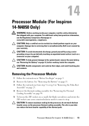
...Battery" on page 13, before working inside the computer. 14 Processor Module (For Inspiron 14-N4050 Only) WARNING: Before working inside your computer, read the safety information that is not authorized by Dell is not covered by your computer. See "Removing the ...until it comes to the system board, remove the main battery, see the Regulatory Compliance Homepage at www.dell.com/regulatory_compliance. Damage due to step 8 in your skin can reduce the heat transfer capability of the... transfer areas on page 9. 2 Remove the battery. Processor Module (For Inspiron 14-N4050 Only) 51
...Battery" on page 13, before working inside the computer. 14 Processor Module (For Inspiron 14-N4050 Only) WARNING: Before working inside your computer, read the safety information that is not authorized by Dell is not covered by your computer. See "Removing the ...until it comes to the system board, remove the main battery, see the Regulatory Compliance Homepage at www.dell.com/regulatory_compliance. Damage due to step 8 in your skin can reduce the heat transfer capability of the... transfer areas on page 9. 2 Remove the battery. Processor Module (For Inspiron 14-N4050 Only) 51
Owner's Manual
Page 52
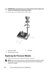
Be careful not to illustrate proper installation is shipped. 52 Processor Module (For Inspiron 14-N4050 Only) NOTE: If you install a new processor, a new thermal assembly including an affixed thermal pad or a new thermal pad along with documentation to bend the pins on the processor module. 6 Lift the processor module from the ZIF socket. 3 1 2 1 processor module 3 ZIF-socket cam screw 2 ZIF socket Replacing the Processor Module 1 Follow the instructions in "Before You Begin" on page 9. CAUTION: When removing the processor module, pull the module straight up.
Be careful not to illustrate proper installation is shipped. 52 Processor Module (For Inspiron 14-N4050 Only) NOTE: If you install a new processor, a new thermal assembly including an affixed thermal pad or a new thermal pad along with documentation to bend the pins on the processor module. 6 Lift the processor module from the ZIF socket. 3 1 2 1 processor module 3 ZIF-socket cam screw 2 ZIF socket Replacing the Processor Module 1 Follow the instructions in "Before You Begin" on page 9. CAUTION: When removing the processor module, pull the module straight up.
Owner's Manual
Page 53
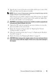
... module is not seated properly. CAUTION: Before turning on page 28. 6 Replace the battery. Processor Module (For Inspiron 14-N4050 Only) 53 2 Align the pin-1 corner of the processor module with the triangle on page 14. CAUTION: To avoid damage to the processor, hold the screwdriver perpendicular to the processor when turning the cam...
... module is not seated properly. CAUTION: Before turning on page 28. 6 Replace the battery. Processor Module (For Inspiron 14-N4050 Only) 53 2 Align the pin-1 corner of the processor module with the triangle on page 14. CAUTION: To avoid damage to the processor, hold the screwdriver perpendicular to the processor when turning the cam...

Owner's Manual
Page 54
54 Processor Module (For Inspiron 14-N4050 Only)
54 Processor Module (For Inspiron 14-N4050 Only)


