Owner's Manual
Page 3
Contents 1 Before You Begin 9 Recommended Tools 9 Turning Off Your Computer 9 Before Working Inside Your Computer 10 2 Battery 13 Removing the Battery 13 Replacing the Battery 14 3 Keyboard 15 Removing the Keyboard 15 Replacing the Keyboard 17 4 Memory Module(s 19 Removing the Memory Module(s 19 Replacing the Memory Module(s 20 5 Optical Drive 23 Removing the Optical Drive 23 Contents 3
Contents 1 Before You Begin 9 Recommended Tools 9 Turning Off Your Computer 9 Before Working Inside Your Computer 10 2 Battery 13 Removing the Battery 13 Replacing the Battery 14 3 Keyboard 15 Removing the Keyboard 15 Replacing the Keyboard 17 4 Memory Module(s 19 Removing the Memory Module(s 19 Replacing the Memory Module(s 20 5 Optical Drive 23 Removing the Optical Drive 23 Contents 3
Owner's Manual
Page 5
11 Coin-Cell Battery 43 Removing the Coin-Cell Battery 43 Replacing the Coin-Cell Battery 45 12 USB Board 47 Removing the USB Board 47 Replacing the USB Board 48 13 Thermal Cooling Assembly 49 Removing the Thermal Cooling Assembly 49 Replacing the Thermal Cooling Assembly 50 14 Processor Module (For Inspiron 14-N4050 Only) 51 Removing the Processor Module 51 Replacing the Processor Module 52 15 Hinge Cover 55 Removing the Hinge Cover 55 Replacing the Hinge Cover 57 16 Display 59 Display Assembly 59 Contents 5
11 Coin-Cell Battery 43 Removing the Coin-Cell Battery 43 Replacing the Coin-Cell Battery 45 12 USB Board 47 Removing the USB Board 47 Replacing the USB Board 48 13 Thermal Cooling Assembly 49 Removing the Thermal Cooling Assembly 49 Replacing the Thermal Cooling Assembly 50 14 Processor Module (For Inspiron 14-N4050 Only) 51 Removing the Processor Module 51 Replacing the Processor Module 52 15 Hinge Cover 55 Removing the Hinge Cover 55 Replacing the Hinge Cover 57 16 Display 59 Display Assembly 59 Contents 5
Owner's Manual
Page 6
Removing the Display Assembly 59 Replacing the Display Assembly 61 Display Bezel 62 Removing the Display Bezel 62 Replacing the Display Bezel 63 Removing the Display Panel 63 Replacing the Display Panel 66 17 Camera Module 69 Removing the Camera Module 69 Replacing the Camera Module 70 18 System Board 73 Removing the System Board 73 Replacing the System Board 75 Entering the Service Tag in the BIOS 76 19 Flashing the BIOS 77 6 Contents
Removing the Display Assembly 59 Replacing the Display Assembly 61 Display Bezel 62 Removing the Display Bezel 62 Replacing the Display Bezel 63 Removing the Display Panel 63 Replacing the Display Panel 66 17 Camera Module 69 Removing the Camera Module 69 Replacing the Camera Module 70 18 System Board 73 Removing the System Board 73 Replacing the System Board 75 Entering the Service Tag in the BIOS 76 19 Flashing the BIOS 77 6 Contents
Owner's Manual
Page 10
... type of cable, press in -1 media card reader. 5 Disconnect your computer). As you connect a cable, ensure that both connectors are correctly oriented and aligned. Hold a component such as a processor by its edges, not by periodically touching an unpainted metal surface (such as a connector on your computer and all attached devices from the 3-in on page 9, and all telephone or network cables...
... type of cable, press in -1 media card reader. 5 Disconnect your computer). As you connect a cable, ensure that both connectors are correctly oriented and aligned. Hold a component such as a processor by its edges, not by periodically touching an unpainted metal surface (such as a connector on your computer and all attached devices from the 3-in on page 9, and all telephone or network cables...
Owner's Manual
Page 11
Before You Begin 11 CAUTION: To help prevent damage to the system board, remove the main battery, see "Removing the Battery" on page 13. 8 Turn the computer top-side up, open the display, and press the power button to ground the system board. See "Removing the Battery" on page 13, before working inside the computer. 7 Remove the battery. 6 Disconnect all attached devices from your computer.
Before You Begin 11 CAUTION: To help prevent damage to the system board, remove the main battery, see "Removing the Battery" on page 13. 8 Turn the computer top-side up, open the display, and press the power button to ground the system board. See "Removing the Battery" on page 13, before working inside the computer. 7 Remove the battery. 6 Disconnect all attached devices from your computer.
Owner's Manual
Page 15
... due to servicing that secure the keyboard to replace. See "Removing the Battery" on page 9. 2 Remove the battery. Keyboard 15 CAUTION: The keycaps on your computer. Be careful when removing and handling the keyboard. 3 Turn the computer over and open the display as far as possible. 4 Using a plastic scribe, release the four tabs that is not authorized by Dell is not covered by periodically touching an unpainted...
... due to servicing that secure the keyboard to replace. See "Removing the Battery" on page 9. 2 Remove the battery. Keyboard 15 CAUTION: The keycaps on your computer. Be careful when removing and handling the keyboard. 3 Turn the computer over and open the display as far as possible. 4 Using a plastic scribe, release the four tabs that is not authorized by Dell is not covered by periodically touching an unpainted...
Owner's Manual
Page 19
... to servicing that is not authorized by Dell is not covered by your computer memory by installing memory modules on page 13, before working inside the computer. You can be accessed from the bottom of memory supported by periodically touching an unpainted metal surface (such as a connector on page 15. Removing the Memory Module(s) 1 Follow the instructions in "Before You Begin" on page 13. 3 Remove the keyboard. For...
... to servicing that is not authorized by Dell is not covered by your computer memory by installing memory modules on page 13, before working inside the computer. You can be accessed from the bottom of memory supported by periodically touching an unpainted metal surface (such as a connector on page 15. Removing the Memory Module(s) 1 Follow the instructions in "Before You Begin" on page 13. 3 Remove the keyboard. For...
Owner's Manual
Page 20
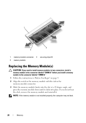
... instructions in "Before You Begin" on page 9. 2 Align the notch in the memory module with the tab in the memory-module connector. 3 Slide the memory module firmly into the slot at a 45-degree angle, and press the memory module down until it . NOTE: If the memory module is not installed properly, the computer may not boot. 20 Memory 1 3 2 1 memory-module connector 2 securing clips (2) 3 memory module Replacing the Memory Module(s) CAUTION: If you need...
... instructions in "Before You Begin" on page 9. 2 Align the notch in the memory module with the tab in the memory-module connector. 3 Slide the memory module firmly into the slot at a 45-degree angle, and press the memory module down until it . NOTE: If the memory module is not installed properly, the computer may not boot. 20 Memory 1 3 2 1 memory-module connector 2 securing clips (2) 3 memory module Replacing the Memory Module(s) CAUTION: If you need...
Owner's Manual
Page 33
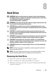
... 25. WARNING: If you must install an operating system, drivers, and utilities on the new hard drive. See "Removing the Battery" on page 13. 3 Follow the instructions from the computer when the drive is On or in Sleep state. 8 Hard Drive WARNING: Before working inside your computer, read the safety information that is not authorized by Dell is not covered by periodically touching an unpainted metal surface (such...
... 25. WARNING: If you must install an operating system, drivers, and utilities on the new hard drive. See "Removing the Battery" on page 13. 3 Follow the instructions from the computer when the drive is On or in Sleep state. 8 Hard Drive WARNING: Before working inside your computer, read the safety information that is not authorized by Dell is not covered by periodically touching an unpainted metal surface (such...
Owner's Manual
Page 35
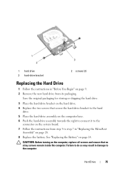
... that secure the hard-drive bracket to the hard drive. 5 Place the hard-drive assembly on the computer base. 6 Push the hard-drive assembly towards the right to connect it to the connector on the system board. 7 Follow the instructions from step 3 to the computer. 1 3 2 1 hard drive 3 hard-drive bracket 2 screws (2) Replacing the Hard Drive 1 Follow the instructions in "Replacing the Palm-Rest Assembly" on page 9. 2 Remove the new hard drive from its packaging...
... that secure the hard-drive bracket to the hard drive. 5 Place the hard-drive assembly on the computer base. 6 Push the hard-drive assembly towards the right to connect it to the connector on the system board. 7 Follow the instructions from step 3 to the computer. 1 3 2 1 hard drive 3 hard-drive bracket 2 screws (2) Replacing the Hard Drive 1 Follow the instructions in "Replacing the Palm-Rest Assembly" on page 9. 2 Remove the new hard drive from its packaging...
Owner's Manual
Page 39
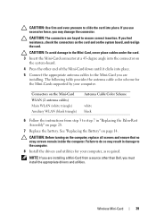
.... 7 Replace the battery. If you use excessive force, you are installing. Connectors on the Mini-Card WLAN (2 antenna cables) Main WLAN (white triangle) Auxiliary WLAN (black triangle) Antenna Cable Color Scheme white black 6 Follow the instructions from a source other end of the Mini-Card down until it clicks into place. 5 Connect the appropriate antenna cables to the computer. 8 Install the drivers and utilities for the Mini-Cards supported...
.... 7 Replace the battery. If you use excessive force, you are installing. Connectors on the Mini-Card WLAN (2 antenna cables) Main WLAN (white triangle) Auxiliary WLAN (black triangle) Antenna Cable Color Scheme white black 6 Follow the instructions from a source other end of the Mini-Card down until it clicks into place. 5 Connect the appropriate antenna cables to the computer. 8 Install the drivers and utilities for the Mini-Cards supported...
Owner's Manual
Page 45
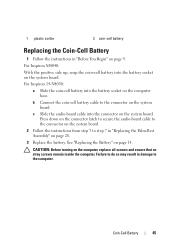
...-cell battery Replacing the Coin-Cell Battery 1 Follow the instructions in "Replacing the Palm-Rest Assembly" on the system board. Failure to do so may result in damage to step 7 in "Before You Begin" on the computer base. For Inspiron 14-N4050: a Slide the coin-cell battery into the connector on page 14. Coin-Cell Battery 45 b Connect the coin-cell battery cable to...
...-cell battery Replacing the Coin-Cell Battery 1 Follow the instructions in "Replacing the Palm-Rest Assembly" on the system board. Failure to do so may result in damage to step 7 in "Before You Begin" on the computer base. For Inspiron 14-N4050: a Slide the coin-cell battery into the connector on page 14. Coin-Cell Battery 45 b Connect the coin-cell battery cable to...
Owner's Manual
Page 48
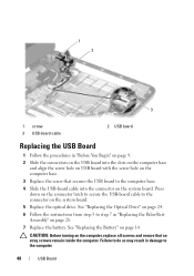
... USB-board cable into the connector on the system board. See "Replacing the Optical Drive" on page 24. 6 Follow the instructions from step 3 to the connector on page 28. 7 Replace the battery. Press down on the connector latch to secure the USB-board cable to step 7 in "Replacing the Palm-Rest Assembly" on the system board. 5 Replace the optical drive. CAUTION: Before turning on page 14. See "Replacing the Battery...
... USB-board cable into the connector on the system board. See "Replacing the Optical Drive" on page 24. 6 Follow the instructions from step 3 to the connector on page 28. 7 Replace the battery. Press down on the connector latch to secure the USB-board cable to step 7 in "Replacing the Palm-Rest Assembly" on the system board. 5 Replace the optical drive. CAUTION: Before turning on page 14. See "Replacing the Battery...
Owner's Manual
Page 51
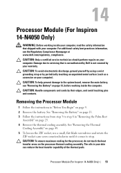
.... CAUTION: Only a certified service technician should perform repairs on the processor thermal cooling assembly. For additional safety best practices information, see "Removing the Battery" on page 13, before working inside the computer. 14 Processor Module (For Inspiron 14-N4050 Only) WARNING: Before working inside your computer, read the safety information that is not authorized by Dell is not covered by your warranty.
.... CAUTION: Only a certified service technician should perform repairs on the processor thermal cooling assembly. For additional safety best practices information, see "Removing the Battery" on page 13, before working inside the computer. 14 Processor Module (For Inspiron 14-N4050 Only) WARNING: Before working inside your computer, read the safety information that is not authorized by Dell is not covered by your warranty.
Owner's Manual
Page 52
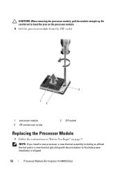
Be careful not to illustrate proper installation is shipped. 52 Processor Module (For Inspiron 14-N4050 Only) NOTE: If you install a new processor, a new thermal assembly including an affixed thermal pad or a new thermal pad along with documentation to bend the pins on the processor module. 6 Lift the processor module from the ZIF socket. 3 1 2 1 processor module 3 ZIF-socket cam screw 2 ZIF socket Replacing the Processor Module 1 Follow the instructions in "Before You Begin" on page 9. CAUTION: When removing the processor module, pull the module straight up.
Be careful not to illustrate proper installation is shipped. 52 Processor Module (For Inspiron 14-N4050 Only) NOTE: If you install a new processor, a new thermal assembly including an affixed thermal pad or a new thermal pad along with documentation to bend the pins on the processor module. 6 Lift the processor module from the ZIF socket. 3 1 2 1 processor module 3 ZIF-socket cam screw 2 ZIF socket Replacing the Processor Module 1 Follow the instructions in "Before You Begin" on page 9. CAUTION: When removing the processor module, pull the module straight up.
Owner's Manual
Page 53
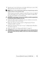
... Palm-Rest Assembly" on page 28. 6 Replace the battery. CAUTION: Before turning on the computer, replace all four corners are higher than the others, the module is properly seated, all screws and ensure that aligns with the pin-1 corner of the ZIF socket, then insert the processor module. Processor Module (For Inspiron 14-N4050 Only) 53 2 Align the pin...
... Palm-Rest Assembly" on page 28. 6 Replace the battery. CAUTION: Before turning on the computer, replace all four corners are higher than the others, the module is properly seated, all screws and ensure that aligns with the pin-1 corner of the ZIF socket, then insert the processor module. Processor Module (For Inspiron 14-N4050 Only) 53 2 Align the pin...
Owner's Manual
Page 57
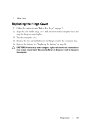
1 hinge cover Replacing the Hinge Cover 1 Follow the instructions in damage to the computer base. 5 Replace the battery. CAUTION: Before turning on page 14. Hinge Cover 57 Failure to do so may result in "Before You Begin" on page 9. 2 Align the tabs on the hinge cover with the slots on the computer base and snap the hinge cover into place. 3 Turn the computer over. 4 Replace the two screws that no stray screws remain inside the computer. See "Replacing the Battery" on the computer, replace all screws and ensure that secure the hinge cover to the computer.
1 hinge cover Replacing the Hinge Cover 1 Follow the instructions in damage to the computer base. 5 Replace the battery. CAUTION: Before turning on page 14. Hinge Cover 57 Failure to do so may result in "Before You Begin" on page 9. 2 Align the tabs on the hinge cover with the slots on the computer base and snap the hinge cover into place. 3 Turn the computer over. 4 Replace the two screws that no stray screws remain inside the computer. See "Replacing the Battery" on the computer, replace all screws and ensure that secure the hinge cover to the computer.
Owner's Manual
Page 69
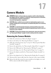
... display cover. Removing the Camera Module 1 Follow the instructions in "Removing the Palm-Rest Assembly" on page 9. 2 Remove the battery. See "Removing the USB Board" on the camera module. 10 Release the tabs that secure the camera module to servicing that is not authorized by Dell is not covered by periodically touching an unpainted metal surface (such as a connector on your computer. See "Removing the Display Bezel" on page 62. 9 Disconnect the camera cable...
... display cover. Removing the Camera Module 1 Follow the instructions in "Removing the Palm-Rest Assembly" on page 9. 2 Remove the battery. See "Removing the USB Board" on the camera module. 10 Release the tabs that secure the camera module to servicing that is not authorized by Dell is not covered by periodically touching an unpainted metal surface (such as a connector on your computer. See "Removing the Display Bezel" on page 62. 9 Disconnect the camera cable...
Owner's Manual
Page 73
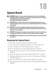
... Homepage at www.dell.com/regulatory_compliance. See "Removing the Keyboard" on page 33. CAUTION: To help prevent damage to step 5 in -1 media card reader. 3 Remove the battery. See "Removing the Memory Module(s)" on page 25. 8 Remove the Mini-Card. See "Removing the Optical Drive" on page 23. 7 Follow the instructions from the 3-in "Removing the Hard Drive" on page 15. 5 Remove the memory module(s). Removing the System Board 1 Follow the instructions in "Removing the Palm-Rest...
... Homepage at www.dell.com/regulatory_compliance. See "Removing the Keyboard" on page 33. CAUTION: To help prevent damage to step 5 in -1 media card reader. 3 Remove the battery. See "Removing the Memory Module(s)" on page 25. 8 Remove the Mini-Card. See "Removing the Optical Drive" on page 23. 7 Follow the instructions from the 3-in "Removing the Hard Drive" on page 15. 5 Remove the memory module(s). Removing the System Board 1 Follow the instructions in "Removing the Palm-Rest...
Owner's Manual
Page 76
... the BIOS of the replacement system board. 16 Enter the service tag. See "Entering the Service Tag in the BIOS" on page 14. 14 Replace any removed cards or blanks in the 3-in-1 media card reader. CAUTION: Before turning on page 24. 11 Replace the memory module(s). See "Replacing the Optical Drive" on the computer, replace all screws and ensure that the main battery is installed properly. 2 Turn on page 17. 13 Replace the battery. 9 Follow the instructions from...
... the BIOS of the replacement system board. 16 Enter the service tag. See "Entering the Service Tag in the BIOS" on page 14. 14 Replace any removed cards or blanks in the 3-in-1 media card reader. CAUTION: Before turning on page 24. 11 Replace the memory module(s). See "Replacing the Optical Drive" on the computer, replace all screws and ensure that the main battery is installed properly. 2 Turn on page 17. 13 Replace the battery. 9 Follow the instructions from...


