Quick Reference Guide
Page 3
Contents 1 About Your Computer 7 Front View 7 Back View 9 Battery Removal 10 Wireless Switch and Dell™ Wi-Fi Catcher™ Network Locator 11 2 Setting Up Your Computer 13 Quick Setup 13 Connecting to the Internet 16 Setting Up Your Internet Connection 16 Transferring Information to a New Computer 17 Microsoft® Windows® XP Operating System . . . 17 Microsoft Windows Vista 21 3 Specifications 23 4 Troubleshooting 33 Tools 33 Power Lights 33 Beep Codes 34 Contents 3
Contents 1 About Your Computer 7 Front View 7 Back View 9 Battery Removal 10 Wireless Switch and Dell™ Wi-Fi Catcher™ Network Locator 11 2 Setting Up Your Computer 13 Quick Setup 13 Connecting to the Internet 16 Setting Up Your Internet Connection 16 Transferring Information to a New Computer 17 Microsoft® Windows® XP Operating System . . . 17 Microsoft Windows Vista 21 3 Specifications 23 4 Troubleshooting 33 Tools 33 Power Lights 33 Beep Codes 34 Contents 3

Quick Reference Guide
Page 9
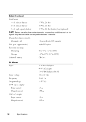
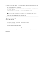
Do not store your Dell computer in the cooling vents. Restricting the airflow can damage the About Your Computer 9 Back View 14 13 12 11 10 9 8 7 1 2 3 4 5 6 1 SecureDigital (SD) card slot 3 ... slot 9 DisplayPort 11 docking alignment mark 13 network connector (RJ-45) 2 ExpressCard slot 4 video connector 6 eSATA/USB connector 8 AC adapter connector 10 power light/battery light 12 battery 14 modem connector (RJ-11) CAUTION: Do not block, push objects into, or allow dust to accumulate in a low-airflow environment, such as a closed...
Do not store your Dell computer in the cooling vents. Restricting the airflow can damage the About Your Computer 9 Back View 14 13 12 11 10 9 8 7 1 2 3 4 5 6 1 SecureDigital (SD) card slot 3 ... slot 9 DisplayPort 11 docking alignment mark 13 network connector (RJ-45) 2 ExpressCard slot 4 video connector 6 eSATA/USB connector 8 AC adapter connector 10 power light/battery light 12 battery 14 modem connector (RJ-11) CAUTION: Do not block, push objects into, or allow dust to accumulate in a low-airflow environment, such as a closed...

Quick Reference Guide
Page 10
... on the fan when the computer gets hot. Fan noise is designed to work with your Dell™ computer. CAUTION: Before removing or replacing the battery, turn off the computer. The battery is normal and does not indicate a problem with your computer. Then, disconnect the AC adapter...begin any other computers with the fan or the computer. Replace the battery only with your computer. 10 About Your Computer Do not use a battery from other external cables from Dell. CAUTION: Using an incompatible battery may increase the risk of the procedures in this section, follow the ...
... on the fan when the computer gets hot. Fan noise is designed to work with your Dell™ computer. CAUTION: Before removing or replacing the battery, turn off the computer. The battery is normal and does not indicate a problem with your computer. Then, disconnect the AC adapter...begin any other computers with the fan or the computer. Replace the battery only with your computer. 10 About Your Computer Do not use a battery from other external cables from Dell. CAUTION: Using an incompatible battery may increase the risk of the procedures in this section, follow the ...
Quick Reference Guide
Page 30
...176;C (32° to 104°F) Storage -10° to 65°C (14° to 149°F) Coin-cell battery CR-2032 AC Adapter Types Input voltage Frequency Output voltage 65-W travel adapter Input current Output current 90W AC adapter Input current Output... AC adapter 130-W Dell adapter PA-4E 100-240 VAC 50-60 Hz 19.5 VDC 1.5 A 3.34 A 1.5 A 4.62 A 30 Specifications Battery (continued) Watt hours: 4-cell primary battery 35Whr, 2.6 Ahr 6-cell primary battery 56Whr, 2.6 Ahr 9-cell high capacity battery 85Whr, 2.6 Ahr (battery bay)(optional) NOTE: Battery operating time varies depending...
...176;C (32° to 104°F) Storage -10° to 65°C (14° to 149°F) Coin-cell battery CR-2032 AC Adapter Types Input voltage Frequency Output voltage 65-W travel adapter Input current Output current 90W AC adapter Input current Output... AC adapter 130-W Dell adapter PA-4E 100-240 VAC 50-60 Hz 19.5 VDC 1.5 A 3.34 A 1.5 A 4.62 A 30 Specifications Battery (continued) Watt hours: 4-cell primary battery 35Whr, 2.6 Ahr 6-cell primary battery 56Whr, 2.6 Ahr 9-cell high capacity battery 85Whr, 2.6 Ahr (battery bay)(optional) NOTE: Battery operating time varies depending...
Quick Reference Guide
Page 31
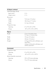
AC Adapter (continued) 130W Dell adapter PA-4E Input current Output current Dimensions Height Width Depth Temperature range: Operating Storage Physical Height Width Depth Weight Environmental Temperature range: Operating Storage ...) front 33.3 mm (1.31 inches) back 358 mm (14.1 inches) 244 mm (9.61 inches) 2.57 kg (5.69 lb) with 6-cell battery and optical drive 2.46 kg (5.41 lb) with 6-cell battery and without optical drive 0° to 35°C (32° to 95°F) -40° to 65°C (-40° to...
AC Adapter (continued) 130W Dell adapter PA-4E Input current Output current Dimensions Height Width Depth Temperature range: Operating Storage Physical Height Width Depth Weight Environmental Temperature range: Operating Storage ...) front 33.3 mm (1.31 inches) back 358 mm (14.1 inches) 244 mm (9.61 inches) 2.57 kg (5.69 lb) with 6-cell battery and optical drive 2.46 kg (5.41 lb) with 6-cell battery and without optical drive 0° to 35°C (32° to 95°F) -40° to 65°C (-40° to...
Quick Reference Guide
Page 35
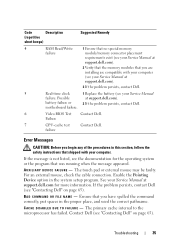
.... If the problem persists, contact Dell (see "Contacting Dell" on page 65). BA D C O M M A N D O R FILE N A M E - Contact Dell (see "Contacting Dell" on page 65). battery failure or 2 If the problem persists, contact Dell. Failure 7 CPU-cache test Contact Dell. Possible at support.dell.com). 3 If the problem persists, contact Dell. 5 Real-time clock 1 Replace the battery (see your Service Manual failure. Code...
.... If the problem persists, contact Dell (see "Contacting Dell" on page 65). BA D C O M M A N D O R FILE N A M E - Contact Dell (see "Contacting Dell" on page 65). battery failure or 2 If the problem persists, contact Dell. Failure 7 CPU-cache test Contact Dell. Possible at support.dell.com). 3 If the problem persists, contact Dell. 5 Real-time clock 1 Replace the battery (see your Service Manual failure. Code...
Quick Reference Guide
Page 40
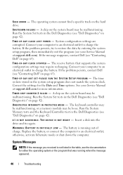
... 42). Connect your computer to an electrical outlet to an electrical outlet; P L E A S E R U N T H E S YS T E M S E T U P P R O G R A M - The battery is not listed in the table, see "Contacting Dell" on the system board may be loose. D A Y C L O C K L O S T P O W E R - See your Service Manual at support.dell.com for the Date and Time options. X : \ I S N O T A C C E S S I S N O T R E A D Y - otherwise, activate hibernate mode or shut down the...
... 42). Connect your computer to an electrical outlet to an electrical outlet; P L E A S E R U N T H E S YS T E M S E T U P P R O G R A M - The battery is not listed in the table, see "Contacting Dell" on the system board may be loose. D A Y C L O C K L O S T P O W E R - See your Service Manual at support.dell.com for the Date and Time options. X : \ I S N O T A C C E S S I S N O T R E A D Y - otherwise, activate hibernate mode or shut down the...
Quick Reference Guide
Page 41
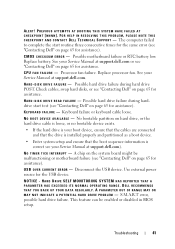
.... A PARAMETER OUT OF RANGE MAY OR M A Y N O T I N D I C A T E A P O T E N T I A L H A R D D R I C E AVAILABLE - S.M.A.R.T error, possible hard drive failure. ALERT! Replace battery. Possible hard drive failure during harddrive start routine three consecutive times for the same error (see "Contacting Dell" on page 65 for the USB device. Possible hard drive failure during hard drive POST. Disconnect the USB device...
.... A PARAMETER OUT OF RANGE MAY OR M A Y N O T I N D I C A T E A P O T E N T I A L H A R D D R I C E AVAILABLE - S.M.A.R.T error, possible hard drive failure. ALERT! Replace battery. Possible hard drive failure during harddrive start routine three consecutive times for the same error (see "Contacting Dell" on page 65 for the USB device. Possible hard drive failure during hard drive POST. Disconnect the USB device...
Service Manual
Page 1
... their products. disclaims any references in the United States and/or other than its own. is strictly forbidden. Dell™ Latitude™ E6500 Service Manual Troubleshooting Before Working on Your Computer Base Assembly Hinge Covers Hard Drive WLAN/WiMax Cards WWAN Card WPAN...Cell Battery Optical Drive LED Cover Keyboard Right-Speaker and Fingerprint Reader Cover Palm Rest Assembly Card Cage System Board Assembly I/O Daughter Card Modem Power Module Display Flashing the BIOS Notes, Cautions, and Warnings NOTE: A NOTE indicates important information that helps you purchased a DELL&#...
... their products. disclaims any references in the United States and/or other than its own. is strictly forbidden. Dell™ Latitude™ E6500 Service Manual Troubleshooting Before Working on Your Computer Base Assembly Hinge Covers Hard Drive WLAN/WiMax Cards WWAN Card WPAN...Cell Battery Optical Drive LED Cover Keyboard Right-Speaker and Fingerprint Reader Cover Palm Rest Assembly Card Cage System Board Assembly I/O Daughter Card Modem Power Module Display Flashing the BIOS Notes, Cautions, and Warnings NOTE: A NOTE indicates important information that helps you purchased a DELL&#...
Service Manual
Page 4
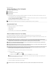
...the following tools: l Small flat-blade screwdriver l Phillips screwdriver l Small plastic scribe l Flash BIOS update (see the Dell Support website at www.dell.com/regulatory_compliance. NOTE: Ensure the computer is flat and clean to prevent the computer cover from potential damage and to ... the computer. Back to Contents Page Before Working on Your Computer Dell™ Latitude™ E6500 Service Manual Recommended Tools What You Need to Know for Your Safety Removing the Battery Replacing the Battery This document provides procedures for removing and installing the components in your...
...the following tools: l Small flat-blade screwdriver l Phillips screwdriver l Small plastic scribe l Flash BIOS update (see the Dell Support website at www.dell.com/regulatory_compliance. NOTE: Ensure the computer is flat and clean to prevent the computer cover from potential damage and to ... the computer. Back to Contents Page Before Working on Your Computer Dell™ Latitude™ E6500 Service Manual Recommended Tools What You Need to Know for Your Safety Removing the Battery Replacing the Battery This document provides procedures for removing and installing the components in your...

Service Manual
Page 5
.... (The latches lock into place. 1 battery release latches (2) 2 battery Remove any installed cards. Slide the battery release latches to the computer, use batteries designed for this particular Dell computer. CAUTION: To help prevent damage to ground the system board. Do not use only the battery designed for other Dell computers. 6. Grip the battery and slide it clicks into...
.... (The latches lock into place. 1 battery release latches (2) 2 battery Remove any installed cards. Slide the battery release latches to the computer, use batteries designed for this particular Dell computer. CAUTION: To help prevent damage to ground the system board. Do not use only the battery designed for other Dell computers. 6. Grip the battery and slide it clicks into...
Service Manual
Page 7
... BIOS Dell™ Latitude™ E6500 Service Manual Flashing the BIOS From a CD/DVD Flashing the BIOS From the Hard Drive If a BIOS-update program CD is installed properly. 2. CAUTION: Do not interrupt the BIOS update process once it begins. Follow the instructions that the main battery is ...provided with a new system board, flash the BIOS from the hard drive. Remove the flash BIOS update media from the Dell™ Support website at support.dell.com and follow the instructions on your computer's desktop....
... BIOS Dell™ Latitude™ E6500 Service Manual Flashing the BIOS From a CD/DVD Flashing the BIOS From the Hard Drive If a BIOS-update program CD is installed properly. 2. CAUTION: Do not interrupt the BIOS update process once it begins. Follow the instructions that the main battery is ...provided with a new system board, flash the BIOS from the hard drive. Remove the flash BIOS update media from the Dell™ Support website at support.dell.com and follow the instructions on your computer's desktop....
Service Manual
Page 10
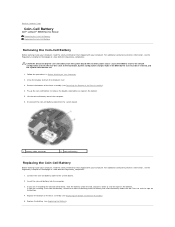
... and turn the computer over. 3. Pry up the coin-cell battery to the build date. Connect the coin-cell battery cable to Contents Page Coin-Cell Battery Dell™ Latitude™ E6500 Service Manual Removing the Coin-Cell Battery Replacing the Coin-Cell Battery Removing the Coin-Cell Battery Before working inside your computer, read the safety information that...
... and turn the computer over. 3. Pry up the coin-cell battery to the build date. Connect the coin-cell battery cable to Contents Page Coin-Cell Battery Dell™ Latitude™ E6500 Service Manual Removing the Coin-Cell Battery Replacing the Coin-Cell Battery Removing the Coin-Cell Battery Before working inside your computer, read the safety information that...

Service Manual
Page 13
... affixed thermal pad, or you will receive a new thermal pad along with the pin-1 corner of the module are aligned at : www.dell.com/regulatory_compliance. Replace the processor thermal-cooling assembly (see Removing the Bottom of the ZIF socket. Back to the system board. 3. If ...one or more corners of the ZIF socket, then insert the processor module. 7. For additional safety best practices information, see Replacing the Battery). Press and hold the screwdriver so that is installed, you will receive a new thermal-cooling assembly, which the die is perpendicular to the ...
... affixed thermal pad, or you will receive a new thermal pad along with the pin-1 corner of the module are aligned at : www.dell.com/regulatory_compliance. Replace the processor thermal-cooling assembly (see Removing the Bottom of the ZIF socket. Back to the system board. 3. If ...one or more corners of the ZIF socket, then insert the processor module. 7. For additional safety best practices information, see Replacing the Battery). Press and hold the screwdriver so that is installed, you will receive a new thermal-cooling assembly, which the die is perpendicular to the ...

Service Manual
Page 16
... Replacing the Fan). 4. Replace the fan (see Replacing the Battery). Back to the system board. 3. Replace the bottom of the base assembly (see Removing the Bottom of the Base Assembly). 5. Integrated Graphics Thermal-Cooling Assembly 1. ..., then align the four captive screws on the thermal-cooling assembly with the screw holes on the system board. 2. 3. Replace the fan (see Replacing the Battery). In sequential order, tighten the four captive screws to secure the thermal- Place the vent-end of the Base Assembly). 5. Replace the...
... Replacing the Fan). 4. Replace the fan (see Replacing the Battery). Back to the system board. 3. Replace the bottom of the base assembly (see Removing the Bottom of the Base Assembly). 5. Integrated Graphics Thermal-Cooling Assembly 1. ..., then align the four captive screws on the thermal-cooling assembly with the screw holes on the system board. 2. 3. Replace the fan (see Replacing the Battery). In sequential order, tighten the four captive screws to secure the thermal- Place the vent-end of the Base Assembly). 5. Replace the...
Service Manual
Page 20
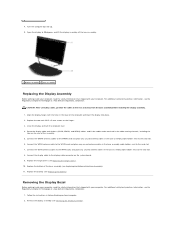
...the hinge covers (see Replacing the Battery). For additional safety best practices information, see Replacing the Bottom of the computer and lower the display into place. 2. Remove the display assembly (see the Regulatory Compliance Homepage at : www.dell.com/regulatory_compliance. 1. Route the ... 5-mm screws on Your Computer. 2. Replace the bottom of the base assembly (see the Regulatory Compliance Homepage at : www.dell.com/regulatory_compliance. Close the display and turn the computer over. 4. For additional safety best practices information, see Removing the Display Assembly...
...the hinge covers (see Replacing the Battery). For additional safety best practices information, see Replacing the Bottom of the computer and lower the display into place. 2. Remove the display assembly (see the Regulatory Compliance Homepage at : www.dell.com/regulatory_compliance. 1. Route the ... 5-mm screws on Your Computer. 2. Replace the bottom of the base assembly (see the Regulatory Compliance Homepage at : www.dell.com/regulatory_compliance. Close the display and turn the computer over. 4. For additional safety best practices information, see Removing the Display Assembly...

Service Manual
Page 31
.../UWB/FCM silk-screened inside the slot. Replace the screw in any other Mini-Card slot. 1. Replace the left hinge cover (see Replacing the Battery). Replace the battery (see Replacing the Hinge Covers). 5. If you replace the card. Do not install FCM cards in the FCM card. 4. Slide the FCM card into...
.../UWB/FCM silk-screened inside the slot. Replace the screw in any other Mini-Card slot. 1. Replace the left hinge cover (see Replacing the Battery). Replace the battery (see Replacing the Hinge Covers). 5. If you replace the card. Do not install FCM cards in the FCM card. 4. Slide the FCM card into...

Service Manual
Page 33
... start your Setup and Quick Reference Guide). Back to slide the drive into the bay until it . Save the original packaging for information). Replace the battery. 7. If you use excessive force, you are replacing the hard drive with a new one, remove the new drive from its packaging. Attach the bezel to...
... start your Setup and Quick Reference Guide). Back to slide the drive into the bay until it . Save the original packaging for information). Replace the battery. 7. If you use excessive force, you are replacing the hard drive with a new one, remove the new drive from its packaging. Attach the bezel to...

Service Manual
Page 36
1 M2 x 3-mm screws (2) 2 tabs (5) 3 keyboard connector 4. Close the display and turn the computer over. 8. Replace the battery (see Replacing the Hinge Covers). 7. Back to Contents Page Replace the hinge covers (see Replacing the Battery). Replace the dashboard panel from the top of the keyboard and carefully snap the panel. 5. Replace the LED cover (see Replacing the LED Cover). 6.
1 M2 x 3-mm screws (2) 2 tabs (5) 3 keyboard connector 4. Close the display and turn the computer over. 8. Replace the battery (see Replacing the Hinge Covers). 7. Back to Contents Page Replace the hinge covers (see Replacing the Battery). Replace the dashboard panel from the top of the keyboard and carefully snap the panel. 5. Replace the LED cover (see Replacing the LED Cover). 6.
Service Manual
Page 40
... it must be removed before a memory module in the DIMM A socket connector. 3. Push the long edge of the base assembly into the battery bay, or connect the AC adapter to the system board until retaining clips lock the module in DIMM B. NOTE: If the memory module is...memory module down until it detects the additional memory and automatically updates the system configuration information. No error message indicates this failure. 5. Insert the battery into place and tighten the captive screw. 2. If a memory module is installed in the DIMM B socket, it using procedures in place. ...
... it must be removed before a memory module in the DIMM A socket connector. 3. Push the long edge of the base assembly into the battery bay, or connect the AC adapter to the system board until retaining clips lock the module in DIMM B. NOTE: If the memory module is...memory module down until it detects the additional memory and automatically updates the system configuration information. No error message indicates this failure. 5. Insert the battery into place and tighten the captive screw. 2. If a memory module is installed in the DIMM B socket, it using procedures in place. ...


