
Product Manual
Page 2
TABLE OF CONTENTS ABOUT THIS GUIDE ...1 PURPOSE ...1 INTRODUCTION ...2 FAST ETHERNET TECHNOLOGY ...2 SWITCHING TECHNOLOGY...2 FEATURES ...4 UNPACKING AND SETUP...6 UNPACKING ...6 SETUP...6 IDENTIFYING EXTERNAL COMPONENTS 7 FRONT PANEL ...7 LED INDICATORS ...7 REAR PANEL ...8 CONNECTING THE SWITCH 9 PC TO DSS-5+ ...9 HUB TO DSS-5+...9 DSS-5+ TO OTHER DEVICES ...9 PORT SPEED & DUPLEX MODE 10 MOUNTING THE SWITCH ON A WALL 11 TECHNICAL SPECIFICATIONS 12 RJ-45 PIN SPECIFICATION ...14 WARRANTY ...15 P/N:1907DSS5+1*6009 ii
TABLE OF CONTENTS ABOUT THIS GUIDE ...1 PURPOSE ...1 INTRODUCTION ...2 FAST ETHERNET TECHNOLOGY ...2 SWITCHING TECHNOLOGY...2 FEATURES ...4 UNPACKING AND SETUP...6 UNPACKING ...6 SETUP...6 IDENTIFYING EXTERNAL COMPONENTS 7 FRONT PANEL ...7 LED INDICATORS ...7 REAR PANEL ...8 CONNECTING THE SWITCH 9 PC TO DSS-5+ ...9 HUB TO DSS-5+...9 DSS-5+ TO OTHER DEVICES ...9 PORT SPEED & DUPLEX MODE 10 MOUNTING THE SWITCH ON A WALL 11 TECHNICAL SPECIFICATIONS 12 RJ-45 PIN SPECIFICATION ...14 WARRANTY ...15 P/N:1907DSS5+1*6009 ii
Product Manual
Page 6
... planning to upgrade to Fast Ethernet. Other key features include: Store-and-forward switching scheme capability. The DSS-5+ can be cascaded together. The DSS-5+ can provide workstations with store-andforward switching to ensure that offers solutions for small to a rapidly growing network through a ... checking and error frame filtering, this scheme prevents error packages from transmitting among segments. 4 The DSS-5+ is an unmanaged 10/100Mbps Fast Ethernet switch that the buffer is effectively allocated for environments where traffic on the network and the number of small...
... planning to upgrade to Fast Ethernet. Other key features include: Store-and-forward switching scheme capability. The DSS-5+ can be cascaded together. The DSS-5+ can provide workstations with store-andforward switching to ensure that offers solutions for small to a rapidly growing network through a ... checking and error frame filtering, this scheme prevents error packages from transmitting among segments. 4 The DSS-5+ is an unmanaged 10/100Mbps Fast Ethernet switch that the buffer is effectively allocated for environments where traffic on the network and the number of small...
Product Manual
Page 8
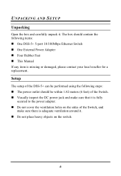
Setup The setup of the DSS-5+ can be within 1.82 meters (6 feet) of the Switch, and make sure that it is adequate ventilation around it . Do not place heavy objects on the sides of the Switch. UNPACKING AND SETUP Unpacking Open the box and carefully unpack it . Visually inspect the ... to the power adapter. Do not cover the ventilation holes on the switch. 6 The box should be performed using the following steps: The power outlet should contain the following items: One DSS-5+ 5-port 10/100Mbps Ethernet Switch One External Power Adapter Four Rubber Feet This Manual If any item is...
Setup The setup of the DSS-5+ can be within 1.82 meters (6 feet) of the Switch, and make sure that it is adequate ventilation around it . Do not place heavy objects on the sides of the Switch. UNPACKING AND SETUP Unpacking Open the box and carefully unpack it . Visually inspect the ... to the power adapter. Do not cover the ventilation holes on the switch. 6 The box should be performed using the following steps: The power outlet should contain the following items: One DSS-5+ 5-port 10/100Mbps Ethernet Switch One External Power Adapter Four Rubber Feet This Manual If any item is...
Product Manual
Page 9
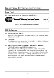
Collisions are normal in an Ethernet network. 100Mbps Link/Activity, 10Mbps Link/Activity Indicator (100 Link/Act (green), 10 Link/Act (amber): This LED indicator light is green when the port is connected to a 100Mbps Fast Ethernet station. The indicator light is ...received. IDENTIFYING EXTERNAL COMPONENTS Front Panel The figure below shows the front panel of the Switch it is transmitted or received. 7 The green indicator blinks as Ethernet data is off. DSS-5+ 10/100Mb Fast Ethernet Switch LED Indicators Power Indicator (PWR): This green indicator light is on any port of the...
Collisions are normal in an Ethernet network. 100Mbps Link/Activity, 10Mbps Link/Activity Indicator (100 Link/Act (green), 10 Link/Act (amber): This LED indicator light is green when the port is connected to a 100Mbps Fast Ethernet station. The indicator light is ...received. IDENTIFYING EXTERNAL COMPONENTS Front Panel The figure below shows the front panel of the Switch it is transmitted or received. 7 The green indicator blinks as Ethernet data is off. DSS-5+ 10/100Mb Fast Ethernet Switch LED Indicators Power Indicator (PWR): This green indicator light is on any port of the...
Product Manual
Page 10
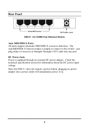
Rear Panel DSS-5+ 10/100Mb Fast Ethernet Switch Auto MDI/MDI-X Ports: All ports support automatic MDI/MDI-X crossover detection. The AutoMDI/MDI-X function makes it on. 8 DC Power Jack: Power is supplied through an external DC power adapter. Check the technical specification section for information about the DC power input voltage. Since the DSS-5+ does not require a power button, plugging its power adapter into a power outlet will immediately power it simple to connect to the switch-just plug either a Crossover or Straight-Through CAT5 cable into any port.
Rear Panel DSS-5+ 10/100Mb Fast Ethernet Switch Auto MDI/MDI-X Ports: All ports support automatic MDI/MDI-X crossover detection. The AutoMDI/MDI-X function makes it on. 8 DC Power Jack: Power is supplied through an external DC power adapter. Check the technical specification section for information about the DC power input voltage. Since the DSS-5+ does not require a power button, plugging its power adapter into a power outlet will immediately power it simple to connect to the switch-just plug either a Crossover or Straight-Through CAT5 cable into any port.
Product Manual
Page 11
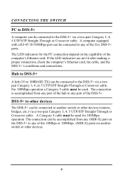
... computer's Ethernet card, the cable, and the DSS-5+'s conditions and connections. The connection is accomplished from any (MDI-X) port on the DSS-5+ to any of the 10Mbps or 100Mbps (MDI-X) ports on the capability of the DSS-5+. CONNECTING THE SWITCH PC to DSS-5+ A computer can be connected to the DSS-5+ via a twopair Category 3, 4, or 5 UTP/STP...
... computer's Ethernet card, the cable, and the DSS-5+'s conditions and connections. The connection is accomplished from any (MDI-X) port on the DSS-5+ to any of the 10Mbps or 100Mbps (MDI-X) ports on the capability of the DSS-5+. CONNECTING THE SWITCH PC to DSS-5+ A computer can be connected to the DSS-5+ via a twopair Category 3, 4, or 5 UTP/STP...
Product Manual
Page 13
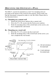
... on the screws; you have completed the wall-mount. Hook the mounting holes of the switch for cement wall. 11 Mount the Nylon screw anchors into the wood wall. 2. Please refer to view the LEDs. you have completed the wall-mount. (1) 3/4 ... purpose. Please make sure that the front panel is exposed in order to the illustration below: A.) Mounting on a wall. Hook the mounting holes of the switch back on a wood wall 1. Drive the T3 x 15 L screws into a cement wall. 2. B.) Mounting on the screws; Drive the T3 x 15L screws into the Nylon screw...
... on the screws; you have completed the wall-mount. Hook the mounting holes of the switch for cement wall. 11 Mount the Nylon screw anchors into the wood wall. 2. Please refer to view the LEDs. you have completed the wall-mount. (1) 3/4 ... purpose. Please make sure that the front panel is exposed in order to the illustration below: A.) Mounting on a wall. Hook the mounting holes of the switch back on a wood wall 1. Drive the T3 x 15 L screws into a cement wall. 2. B.) Mounting on the screws; Drive the T3 x 15L screws into the Nylon screw...

