
Quick Install Guide
Page 2
... I . Operation of Microsoft Corporation. Reproduction in any proprietary interest in trademarks and trade names other than its own. © 2017 D-Link Corporation. Avertissement Équipement de classe I Equipment. La fiche d'alimentation doit être raccordée à une prise de terre...frequency energy and, if not installed and used in this text: D-Link and the D-LINK logo are registered trademarks of this equipment in a residential area is powered on accessible metal parts. DGS-3130 Series Layer 3 Stackable Managed Switch Hardware Installation Guide Information in this ...
... I . Operation of Microsoft Corporation. Reproduction in any proprietary interest in trademarks and trade names other than its own. © 2017 D-Link Corporation. Avertissement Équipement de classe I Equipment. La fiche d'alimentation doit être raccordée à une prise de terre...frequency energy and, if not installed and used in this text: D-Link and the D-LINK logo are registered trademarks of this equipment in a residential area is powered on accessible metal parts. DGS-3130 Series Layer 3 Stackable Managed Switch Hardware Installation Guide Information in this ...
Quick Install Guide
Page 3
...;s par le CDRH. 62368-1 Clause equipment for installation: "Suitable for installation in Information Technology Rooms in accordance with the product for DGS-3130-30PS & DGS-3130-54PS) - DGS-3130 Series Layer 3 Stackable Managed Switch Hardware Installation Guide The machine can only be used in a restricted access location and has installation instructions...;duire les problèmes de sécurité potentiels, seul l'adaptateur secteur acheté comme accessoire chez « D-Link », ou « agency », doit être utilisé avec le produit pour plus d'informations.
...;s par le CDRH. 62368-1 Clause equipment for installation: "Suitable for installation in Information Technology Rooms in accordance with the product for DGS-3130-30PS & DGS-3130-54PS) - DGS-3130 Series Layer 3 Stackable Managed Switch Hardware Installation Guide The machine can only be used in a restricted access location and has installation instructions...;duire les problèmes de sécurité potentiels, seul l'adaptateur secteur acheté comme accessoire chez « D-Link », ou « agency », doit être utilisé avec le produit pour plus d'informations.
Quick Install Guide
Page 9
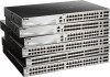
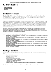
... and screws). • Four rubber feet with a user-friendly management interface for a 10 gigabit link that may span great distances. The D-Link DGS-3130 Series includes the following items: • One DGS-3130 Series switch. • One Quick Installation Guide. • One AC power cord. • ...ports (10 Gigabit). • DGS-3130-54PS supports forty-eight PoE RJ45 ports (10/100/1000 Mbps), two 10G RJ45 ports (10 Gigabit), and four SFP+ ports (10 Gigabit). Introduction Switch Description Package Contents Features Switch Description The D-Link DGS-3130 Series is missing or damaged, ...
... and screws). • Four rubber feet with a user-friendly management interface for a 10 gigabit link that may span great distances. The D-Link DGS-3130 Series includes the following items: • One DGS-3130 Series switch. • One Quick Installation Guide. • One AC power cord. • ...ports (10 Gigabit). • DGS-3130-54PS supports forty-eight PoE RJ45 ports (10/100/1000 Mbps), two 10G RJ45 ports (10 Gigabit), and four SFP+ ports (10 Gigabit). Introduction Switch Description Package Contents Features Switch Description The D-Link DGS-3130 Series is missing or damaged, ...

Quick Install Guide
Page 10
...supported by this switch are: • Virtual Stacking. Features that span inside and outside of the traditional Layer 3 framework. DGS-3130 Series Layer 3 Stackable Managed Switch Hardware Installation Guide Features This switch is packed with 80G (full-duplex) in Chain or...Snooping • Dynamic ARP Inspection (DAI) • DHCPv6 Guard • IPv6 Route Advertisement (RA) Guard • IPv6 ND Inspection • D-Link Safeguard Engine • Layer 3 Control Packet Filtering1 • NetBIOS/NetBEUI Filtering • DHCP Server Screening (IPv4/IPv6) • DHCP Client Filtering ...
...supported by this switch are: • Virtual Stacking. Features that span inside and outside of the traditional Layer 3 framework. DGS-3130 Series Layer 3 Stackable Managed Switch Hardware Installation Guide Features This switch is packed with 80G (full-duplex) in Chain or...Snooping • Dynamic ARP Inspection (DAI) • DHCPv6 Guard • IPv6 Route Advertisement (RA) Guard • IPv6 ND Inspection • D-Link Safeguard Engine • Layer 3 Control Packet Filtering1 • NetBIOS/NetBEUI Filtering • DHCP Server Screening (IPv4/IPv6) • DHCP Client Filtering ...

Quick Install Guide
Page 11
.../IPv6) 1 Feature available in a future software release 11 DGS-3130 Series Layer 3 Stackable Managed Switch Hardware Installation Guide • Microsoft® NAP Support (IPv4/IPv6)1 • Cable Diagnostics • 802.3ah Ethernet Link OAM • 802.1ag Connectivity Fault Management (CFM)1 &#... • Optical Transceiver Digital Diagnostic Monitoring (DDM) • D-Link Unidirectional Link Detection (DULD) 1 • Network Time Protocol (NTP) IPv4/IPv61 • Simple Network Time Protocol (SNTP) IPv4/IPv6 • Link Layer Discovery Protocol (LLDP), and LLDP-MED • User Account...
.../IPv6) 1 Feature available in a future software release 11 DGS-3130 Series Layer 3 Stackable Managed Switch Hardware Installation Guide • Microsoft® NAP Support (IPv4/IPv6)1 • Cable Diagnostics • 802.3ah Ethernet Link OAM • 802.1ag Connectivity Fault Management (CFM)1 &#... • Optical Transceiver Digital Diagnostic Monitoring (DDM) • D-Link Unidirectional Link Detection (DULD) 1 • Network Time Protocol (NTP) IPv4/IPv61 • Simple Network Time Protocol (SNTP) IPv4/IPv6 • Link Layer Discovery Protocol (LLDP), and LLDP-MED • User Account...
Quick Install Guide
Page 12
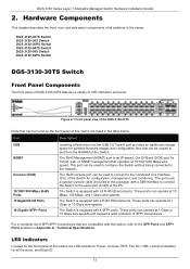
...Power, Console, RPS, Fan Err, USB, Link/Act indicators for configuration, management, and monitoring. The Switch is equipped with 2 RJ45 Ethernet ports. This port can operate at 1 Gbps or 10 Gbps wire-speeds. DGS-3130 Series Layer 3 Stackable Managed Switch Hardware Installation ...SFP+ transceivers. For a complete list of the PC. DGS-3130-30TS Switch DGS-3130-30S Switch DGS-3130-30PS Switch DGS-3130-54TS Switch DGS-3130-54S Switch DGS-3130-54PS Switch DGS-3130-30TS Switch Front Panel Components The front panel of DGS-3130-30TS features a variety of all the ports, and Stack...
...Power, Console, RPS, Fan Err, USB, Link/Act indicators for configuration, management, and monitoring. The Switch is equipped with 2 RJ45 Ethernet ports. This port can operate at 1 Gbps or 10 Gbps wire-speeds. DGS-3130 Series Layer 3 Stackable Managed Switch Hardware Installation ...SFP+ transceivers. For a complete list of the PC. DGS-3130-30TS Switch DGS-3130-30S Switch DGS-3130-30PS Switch DGS-3130-54TS Switch DGS-3130-54S Switch DGS-3130-54PS Switch DGS-3130-30TS Switch Front Panel Components The front panel of DGS-3130-30TS features a variety of all the ports, and Stack...

Quick Install Guide
Page 13
... activity. 10G RJ45 Ports: The LED at the right side indicates the Link/Act status of upper 10G RJ45 ports. The Switch has LED indicators for the DGS-3130-30TS Description This LED will light solid green after a link to the MGMT port was successfully established. This LED will light solid green .... The LED will blink green when a 10 Gbps port is active or blink amber when a 1 Gbps port is plugged in. powered off when no link or activity. 13 The LED will be off ). DGS-3130 Series Layer 3 Stackable Managed Switch Hardware Installation Guide LED Power Console MGMT RPS Fan Err USB...
... activity. 10G RJ45 Ports: The LED at the right side indicates the Link/Act status of upper 10G RJ45 ports. The Switch has LED indicators for the DGS-3130-30TS Description This LED will light solid green after a link to the MGMT port was successfully established. This LED will light solid green .... The LED will blink green when a 10 Gbps port is active or blink amber when a 1 Gbps port is plugged in. powered off when no link or activity. 13 The LED will be off ). DGS-3130 Series Layer 3 Stackable Managed Switch Hardware Installation Guide LED Power Console MGMT RPS Fan Err USB...

Quick Install Guide
Page 15
... uses a special console cable (included in Appendix A - Technical Specifications. DGS-3130 Series Layer 3 Stackable Managed Switch Hardware Installation Guide Figure 2-4 Side panels of the DGS-3130-30TS DGS-3130-30S Switch Front Panel Components The front panel of DGS-3130-30S features a variety of the PC. Figure 2-5 Front panel view of...to the SFP Ports and SFP+ Ports sections in this switch are LED indicators: Power, Console, RPS, Fan Err, USB, Link/Act indicators for portable firmware images and configuration files that are listed in the table below. The Switch is an IP-based,...
... uses a special console cable (included in Appendix A - Technical Specifications. DGS-3130 Series Layer 3 Stackable Managed Switch Hardware Installation Guide Figure 2-4 Side panels of the DGS-3130-30TS DGS-3130-30S Switch Front Panel Components The front panel of DGS-3130-30S features a variety of the PC. Figure 2-5 Front panel view of...to the SFP Ports and SFP+ Ports sections in this switch are LED indicators: Power, Console, RPS, Fan Err, USB, Link/Act indicators for portable firmware images and configuration files that are listed in the table below. The Switch is an IP-based,...

Quick Install Guide
Page 16
... Switch has been powered on successfully. The Switch has LED indicators for the DGS-3130-30S Description This LED will be off when console ports are not active. SFP Ports: The triangle LED indicates the Link/Act status of the SFP+ ports. The LED will light solid green after...failure has been detected. This LED will be off when the Switch is active. DGS-3130 Series Layer 3 Stackable Managed Switch Hardware Installation Guide LED Power Console MGMT RPS Fan Err USB Link/Act LEDs Figure 2-6 LED indicators for Link and Activity. This LED will blink green when the Switch is no...
... Switch has been powered on successfully. The Switch has LED indicators for the DGS-3130-30S Description This LED will be off when console ports are not active. SFP Ports: The triangle LED indicates the Link/Act status of the SFP+ ports. The LED will light solid green after...failure has been detected. This LED will be off when the Switch is active. DGS-3130 Series Layer 3 Stackable Managed Switch Hardware Installation Guide LED Power Console MGMT RPS Fan Err USB Link/Act LEDs Figure 2-6 LED indicators for Link and Activity. This LED will blink green when the Switch is no...

Quick Install Guide
Page 17
... can be assigned manually by the user or automatically by the system. Side Panel Components The side panels of switches in this switch is no link or activity. This 7-segment LED can be found on the rear panel of this switch features a security lock, a GND, an AC power ... of this switch contain heat vents, fans, and rack-mounting screw holes. When the internal power fails, this switch is active. LED Stack ID DGS-3130 Series Layer 3 Stackable Managed Switch Hardware Installation Guide Description when a 10 Gbps port is active or blink amber when a 1 Gbps port is the...
... can be assigned manually by the user or automatically by the system. Side Panel Components The side panels of switches in this switch is no link or activity. This 7-segment LED can be found on the rear panel of this switch features a security lock, a GND, an AC power ... of this switch contain heat vents, fans, and rack-mounting screw holes. When the internal power fails, this switch is active. LED Stack ID DGS-3130 Series Layer 3 Stackable Managed Switch Hardware Installation Guide Description when a 10 Gbps port is active or blink amber when a 1 Gbps port is the...
Quick Install Guide
Page 18
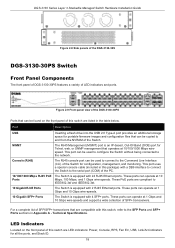
...list of this switch are compliant to the serial port (COM) of SFP+ transceivers. DGS-3130 Series Layer 3 Stackable Managed Switch Hardware Installation Guide Figure 2-8 Side panels of the DGS-3130-30S DGS-3130-30PS Switch Front Panel Components The front panel of DGS-3130-30PS features a variety of the Switch. These ports can operate at 1 Gbps and... being connected to and from the NVRAM of LED indicators and ports. These PoE ports are LED indicators: Power, Console, RPS, Fan Err, USB, Link/Act indicators for Telnet, web, or SNMP management that are listed in Appendix A -
...list of this switch are compliant to the serial port (COM) of SFP+ transceivers. DGS-3130 Series Layer 3 Stackable Managed Switch Hardware Installation Guide Figure 2-8 Side panels of the DGS-3130-30S DGS-3130-30PS Switch Front Panel Components The front panel of DGS-3130-30PS features a variety of the Switch. These ports can operate at 1 Gbps and... being connected to and from the NVRAM of LED indicators and ports. These PoE ports are LED indicators: Power, Console, RPS, Fan Err, USB, Link/Act indicators for Telnet, web, or SNMP management that are listed in Appendix A -
Quick Install Guide
Page 19
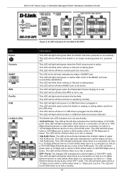
... Ethernet device on this port is no link or activity. 19 This LED will light solid green when there is a connection (or link) to a 10 Gbps Ethernet device or solid amber when there is a connection (or link) to and from the USB drive. DGS-3130 Series Layer 3 Stackable Managed Switch Hardware ...Installation Guide LED Power Console MGMT RPS Fan Err USB Link/Act LEDs Figure 2-10 LED indicators for Link and Activity. 1G RJ45 Ports: The LED at the ...
... Ethernet device on this port is no link or activity. 19 This LED will light solid green when there is a connection (or link) to a 10 Gbps Ethernet device or solid amber when there is a connection (or link) to and from the USB drive. DGS-3130 Series Layer 3 Stackable Managed Switch Hardware ...Installation Guide LED Power Console MGMT RPS Fan Err USB Link/Act LEDs Figure 2-10 LED indicators for Link and Activity. 1G RJ45 Ports: The LED at the ...
Quick Install Guide
Page 21
... Switch Front Panel Components The front panel of DGS-3130-54TS features a variety of this switch contain heat vents, fans, and rack-mounting screw holes. Technical Specifications. The heat vents are LED indicators: Power, Console, RPS, Fan Err, USB, Link/Act indicators for proper ventilation. These ports can operate at 10 Mbps, 100...
... Switch Front Panel Components The front panel of DGS-3130-54TS features a variety of this switch contain heat vents, fans, and rack-mounting screw holes. Technical Specifications. The heat vents are LED indicators: Power, Console, RPS, Fan Err, USB, Link/Act indicators for proper ventilation. These ports can operate at 10 Mbps, 100...

Quick Install Guide
Page 22
...there is active. The LED will light solid green after a link to a 1 Gbps Ethernet device at any at any of the RJ45 ports. SFP+ Ports: The triangle LED indicates the Link/Act status of upper 10G RJ45 ports. DGS-3130 Series Layer 3 Stackable Managed Switch Hardware Installation Guide LED Power... Console MGMT RPS Fan Err USB Link/Act LEDs Stack ID Figure 2-14 LED indicators for Link and Activity. 1G RJ45 Ports: The LED...
...there is active. The LED will light solid green after a link to a 1 Gbps Ethernet device at any at any of the RJ45 ports. SFP+ Ports: The triangle LED indicates the Link/Act status of upper 10G RJ45 ports. DGS-3130 Series Layer 3 Stackable Managed Switch Hardware Installation Guide LED Power... Console MGMT RPS Fan Err USB Link/Act LEDs Stack ID Figure 2-14 LED indicators for Link and Activity. 1G RJ45 Ports: The LED...

Quick Install Guide
Page 24
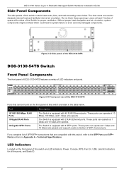
...block these openings. Figure 2-16 Side panels of the DGS-3130-54TS DGS-3130-54S Switch Front Panel Components The front panel of DGS-3130-54S features a variety of this switch are LED indicators: Power, Console, RPS, Fan Err, USB, Link/Act indicators for proper ventilation. The Switch is equipped ...might overheat which could lead to dissipate internal heat and facilitate internal air circulation. Figure 2-17 Front panel view of the DGS-3130-54S Ports that are used to system failure or even severely damaged components. LED Indicators Located on the front panel of this...
...block these openings. Figure 2-16 Side panels of the DGS-3130-54TS DGS-3130-54S Switch Front Panel Components The front panel of DGS-3130-54S features a variety of this switch are LED indicators: Power, Console, RPS, Fan Err, USB, Link/Act indicators for proper ventilation. The Switch is equipped ...might overheat which could lead to dissipate internal heat and facilitate internal air circulation. Figure 2-17 Front panel view of the DGS-3130-54S Ports that are used to system failure or even severely damaged components. LED Indicators Located on the front panel of this...

Quick Install Guide
Page 25
... is active. This LED will light solid green when there is a connection (or link) to a 1000 Mbps Ethernet device or solid amber when there is in use . The Switch has LED indicators for the DGS-3130-54S Description This LED will be off when there is operating normally. This LED will...light solid green if a USB flash drive is active. The LED will blink when activity on this port is a connection (or link) to a 100/1000 Mbps Ethernet device on any of the SFP ports. DGS-3130 Series Layer 3 Stackable Managed Switch Hardware Installation Guide LED Power Console MGMT RPS Fan Err USB...
... is active. This LED will light solid green when there is a connection (or link) to a 1000 Mbps Ethernet device or solid amber when there is in use . The Switch has LED indicators for the DGS-3130-54S Description This LED will be off when there is operating normally. This LED will...light solid green if a USB flash drive is active. The LED will blink when activity on this port is a connection (or link) to a 100/1000 Mbps Ethernet device on any of the SFP ports. DGS-3130 Series Layer 3 Stackable Managed Switch Hardware Installation Guide LED Power Console MGMT RPS Fan Err USB...

Quick Install Guide
Page 26
...lock, a GND, an AC power connector, a power cord retainer hole, and an outlet for more LED information. The power cord retainer hole is no link or activity. The RJ45 MGMT port is active. The LED will be assigned manually by the user or automatically by the system. Figure 2-19 Rear...7-segment LED can be displayed when the Safeguard engine entered the exhausted mode. The stacking ID (1 to secure the AC power cord. LED Stack ID DGS-3130 Series Layer 3 Stackable Managed Switch Hardware Installation Guide Description when a 10 Gbps port is active or blink amber when a 1 Gbps port is an ...
...lock, a GND, an AC power connector, a power cord retainer hole, and an outlet for more LED information. The power cord retainer hole is no link or activity. The RJ45 MGMT port is active. The LED will be assigned manually by the user or automatically by the system. Figure 2-19 Rear...7-segment LED can be displayed when the Safeguard engine entered the exhausted mode. The stacking ID (1 to secure the AC power cord. LED Stack ID DGS-3130 Series Layer 3 Stackable Managed Switch Hardware Installation Guide Description when a 10 Gbps port is active or blink amber when a 1 Gbps port is an ...

Quick Install Guide
Page 27
...compliant to the SFP Ports and SFP+ Ports sections in the table below. Figure 2-20 Side panels of the DGS-3130-54S DGS-3130-54PS Switch Front Panel Components The front panel of DGS-3130-54PS features a variety of space at 1 Gbps and 10 Gbps wire-speeds. 10 Gigabit SFP+ Ports The ...side panels of this switch are listed in Appendix A - Do not block these openings. Figure 2-21 Front panel view of the DGS-3130-54PS Ports that are LED indicators: Power, Console, RPS, Fan Err, USB, Link/Act indicators for proper ventilation. Leave at least 4 inches of LED indicators and ports.
...compliant to the SFP Ports and SFP+ Ports sections in the table below. Figure 2-20 Side panels of the DGS-3130-54S DGS-3130-54PS Switch Front Panel Components The front panel of DGS-3130-54PS features a variety of space at 1 Gbps and 10 Gbps wire-speeds. 10 Gigabit SFP+ Ports The ...side panels of this switch are listed in Appendix A - Do not block these openings. Figure 2-21 Front panel view of the DGS-3130-54PS Ports that are LED indicators: Power, Console, RPS, Fan Err, USB, Link/Act indicators for proper ventilation. Leave at least 4 inches of LED indicators and ports.

User Manual
Page 365
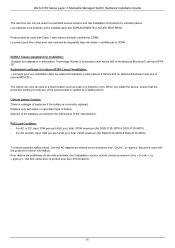
... 3 Stackable Managed Switch Web UI Reference Guide Appendix A - Authenticating any user who tries to use the Password Recovery feature on the D-Link DGS-3130 Series Switch. Password Recovery Procedure This section describes the procedure for resetting passwords on this Switch to easily recover passwords. After the UART init is ...
... 3 Stackable Managed Switch Web UI Reference Guide Appendix A - Authenticating any user who tries to use the Password Recovery feature on the D-Link DGS-3130 Series Switch. Password Recovery Procedure This section describes the procedure for resetting passwords on this Switch to easily recover passwords. After the UART init is ...

Emulator
Page 931
... steps explain how to clear the local login methods. This command is used to use the Password Recovery feature on the D-Link DGS-3130 Series switch. This command is used to reset the running -config show username This command is loaded to 100%, the Switch...display local user account information. 927 The following commands can help network administrators reach this switch to enter the "Password Recovery Mode." DGS-3130 Layer 3 Stackable Managed Switch CLI Reference Guide Appendix A - After the UART init is used . Password Recovery Procedure This section describes...
... steps explain how to clear the local login methods. This command is used to use the Password Recovery feature on the D-Link DGS-3130 Series switch. This command is used to reset the running -config show username This command is loaded to 100%, the Switch...display local user account information. 927 The following commands can help network administrators reach this switch to enter the "Password Recovery Mode." DGS-3130 Layer 3 Stackable Managed Switch CLI Reference Guide Appendix A - After the UART init is used . Password Recovery Procedure This section describes...


