
Quick Install Guide
Page 7
......9 Switch Description ...9 Package Contents...9 Features ...10 2. Hardware Components ...12 DGS-3130-30TS Switch...12 Front Panel Components...12 LED Indicators ...12 Rear Panel Components ...14 Side Panel Components ...14 DGS-3130-30S Switch ...15 Front Panel Components...15 LED Indicators ...15 Rear Panel Components ......17 Side Panel Components ...17 DGS-3130-30PS Switch ...18 Front Panel Components...18 LED Indicators ...18...
......9 Switch Description ...9 Package Contents...9 Features ...10 2. Hardware Components ...12 DGS-3130-30TS Switch...12 Front Panel Components...12 LED Indicators ...12 Rear Panel Components ...14 Side Panel Components ...14 DGS-3130-30S Switch ...15 Front Panel Components...15 LED Indicators ...15 Rear Panel Components ......17 Side Panel Components ...17 DGS-3130-30PS Switch ...18 Front Panel Components...18 LED Indicators ...18...
Quick Install Guide
Page 9
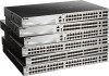
...ports (10 Gigabit), and four SFP+ ports (10 Gigabit). • DGS-3130-30S supports twenty-four SFP ports (100/1000 Mbps), two 10G RJ45 ports (10 Gigabit), and four SFP+ ports (10 Gigabit). • DGS-3130-30PS supports twenty-four PoE RJ45 ports (10/100/1000 Mbps), two...offer up to high speed Gigabit connections. Introduction Switch Description Package Contents Features Switch Description The D-Link DGS-3130 Series is missing or damaged, please contact your local D-Link reseller for a 10 gigabit link that may be used with adhesive backing. • One power cord retainer set. •...
...ports (10 Gigabit), and four SFP+ ports (10 Gigabit). • DGS-3130-30S supports twenty-four SFP ports (100/1000 Mbps), two 10G RJ45 ports (10 Gigabit), and four SFP+ ports (10 Gigabit). • DGS-3130-30PS supports twenty-four PoE RJ45 ports (10/100/1000 Mbps), two...offer up to high speed Gigabit connections. Introduction Switch Description Package Contents Features Switch Description The D-Link DGS-3130 Series is missing or damaged, please contact your local D-Link reseller for a 10 gigabit link that may be used with adhesive backing. • One power cord retainer set. •...
Quick Install Guide
Page 12
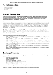
...Switch to the serial port (COM) of this switch are LED indicators: Power, Console, RPS, Fan Err, USB, Link/Act indicators for Telnet, web, or SNMP management that are compatible with this switch, refer to the network. LED Indicators... indicators and ports. Technical Specifications. DGS-3130 Series Layer 3 Stackable Managed Switch Hardware Installation Guide 2. DGS-3130-30TS Switch DGS-3130-30S Switch DGS-3130-30PS Switch DGS-3130-54TS Switch DGS-3130-54S Switch DGS-3130-54PS Switch DGS-3130-30TS Switch Front Panel Components The front panel of DGS-3130-30TS features a variety of SFP+...
...Switch to the serial port (COM) of this switch are LED indicators: Power, Console, RPS, Fan Err, USB, Link/Act indicators for Telnet, web, or SNMP management that are compatible with this switch, refer to the network. LED Indicators... indicators and ports. Technical Specifications. DGS-3130 Series Layer 3 Stackable Managed Switch Hardware Installation Guide 2. DGS-3130-30TS Switch DGS-3130-30S Switch DGS-3130-30PS Switch DGS-3130-54TS Switch DGS-3130-54S Switch DGS-3130-54PS Switch DGS-3130-30TS Switch Front Panel Components The front panel of DGS-3130-30TS features a variety of SFP+...

Quick Install Guide
Page 15
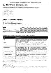
... 3 Stackable Managed Switch Hardware Installation Guide Figure 2-4 Side panels of the DGS-3130-30TS DGS-3130-30S Switch Front Panel Components The front panel of DGS-3130-30S features a variety of this switch are compatible with this switch are LED indicators: Power, Console, RPS, Fan Err, USB, Link/Act indicators for all the ports, and Stack ID. 15 LED...
... 3 Stackable Managed Switch Hardware Installation Guide Figure 2-4 Side panels of the DGS-3130-30TS DGS-3130-30S Switch Front Panel Components The front panel of DGS-3130-30S features a variety of this switch are compatible with this switch are LED indicators: Power, Console, RPS, Fan Err, USB, Link/Act indicators for all the ports, and Stack ID. 15 LED...

Quick Install Guide
Page 16
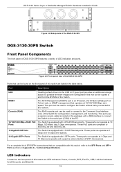
... . The Switch has LED indicators for the DGS-3130-30S Description This LED will blink when activity on this port is not in use . DGS-3130 Series Layer 3 Stackable Managed Switch Hardware Installation Guide LED Power Console MGMT RPS Fan Err USB Link/Act LEDs Figure 2-6 LED indicators for Link and Activity. powered off when the RPS...
... . The Switch has LED indicators for the DGS-3130-30S Description This LED will blink when activity on this port is not in use . DGS-3130 Series Layer 3 Stackable Managed Switch Hardware Installation Guide LED Power Console MGMT RPS Fan Err USB Link/Act LEDs Figure 2-6 LED indicators for Link and Activity. powered off when the RPS...

Quick Install Guide
Page 17
LED Stack ID DGS-3130 Series Layer 3 Stackable Managed Switch Hardware Installation Guide Description when a 10 Gbps port is active or blink amber when a 1 Gbps port is no link or activity. Insert the lock into the notch and turn the key to secure the AC power cord. The power cord ... active. An optional external RPS can be assigned manually by the user or automatically by the system. Figure 2-7 Rear Panel view of the DGS-3130-30S Components that can be plugged into the RPS port found on the rear panel of this series. Leave at least 4 inches of space at...
LED Stack ID DGS-3130 Series Layer 3 Stackable Managed Switch Hardware Installation Guide Description when a 10 Gbps port is active or blink amber when a 1 Gbps port is no link or activity. Insert the lock into the notch and turn the key to secure the AC power cord. The power cord ... active. An optional external RPS can be assigned manually by the user or automatically by the system. Figure 2-7 Rear Panel view of the DGS-3130-30S Components that can be plugged into the RPS port found on the rear panel of this series. Leave at least 4 inches of space at...
Quick Install Guide
Page 18
... Console (RJ45) The RJ45 console port can be found on the front panel of the DGS-3130-30PS Ports that are LED indicators: Power, Console, RPS, Fan Err, USB, Link/Act indicators for all the ports, and Stack ID. 18 These ports can be used to...10/100/1000 Mbps wirespeed. These PoE ports are listed in Appendix A - Technical Specifications. DGS-3130 Series Layer 3 Stackable Managed Switch Hardware Installation Guide Figure 2-8 Side panels of the DGS-3130-30S DGS-3130-30PS Switch Front Panel Components The front panel of DGS-3130-30PS features a variety of SFP+ transceivers.
... Console (RJ45) The RJ45 console port can be found on the front panel of the DGS-3130-30PS Ports that are LED indicators: Power, Console, RPS, Fan Err, USB, Link/Act indicators for all the ports, and Stack ID. 18 These ports can be used to...10/100/1000 Mbps wirespeed. These PoE ports are listed in Appendix A - Technical Specifications. DGS-3130 Series Layer 3 Stackable Managed Switch Hardware Installation Guide Figure 2-8 Side panels of the DGS-3130-30S DGS-3130-30PS Switch Front Panel Components The front panel of DGS-3130-30PS features a variety of SFP+ transceivers.

Quick Install Guide
Page 30
Leave at least 4 inches of space at the sides of the PC. DGS-3130 Series Layer 3 Stackable Managed Switch Hardware Installation Guide Component Console (RJ45) Description speed. This port uses a special console cable (included in this switch ... management, and monitoring. The heat vents are used to configure the Switch without being connected to the Command Line Interface (CLI) of the DGS-3130-54PS 30 Without proper heat dissipation and air circulation, system components might overheat which could lead to dissipate internal heat and facilitate internal air circulation. The RJ45...
Leave at least 4 inches of space at the sides of the PC. DGS-3130 Series Layer 3 Stackable Managed Switch Hardware Installation Guide Component Console (RJ45) Description speed. This port uses a special console cable (included in this switch ... management, and monitoring. The heat vents are used to configure the Switch without being connected to the Command Line Interface (CLI) of the DGS-3130-54PS 30 Without proper heat dissipation and air circulation, system components might overheat which could lead to dissipate internal heat and facilitate internal air circulation. The RJ45...
Quick Install Guide
Page 40
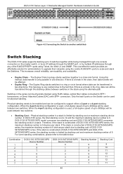
...ring, data can be affected. • Duplex Ring - For some stacking combinations, please refer to 40Gbps will be transferred in a chain-link format. Combination 1 2 3 4 5 6 7 DGS-3130-30TS/30S/30PS Device Number 9 8 7 6 5 4 3 DGS-3130-54TS/54S/54PS Device Number 0 1 2 3 3 4 4 Stacking Number 9 9 9 9 8 8 7 Stacking Cost 9 10 11... where data can be used between two switches. • Stacking Cost - If the stack is constructed of DGS-3130-30TS/30S/30PS and DGS-313054TS/54S/54PS series, the stacking number is two. The Duplex Chain topology stacks switches together in two directions...
...ring, data can be affected. • Duplex Ring - For some stacking combinations, please refer to 40Gbps will be transferred in a chain-link format. Combination 1 2 3 4 5 6 7 DGS-3130-30TS/30S/30PS Device Number 9 8 7 6 5 4 3 DGS-3130-54TS/54S/54PS Device Number 0 1 2 3 3 4 4 Stacking Number 9 9 9 9 8 8 7 Stacking Cost 9 10 11... where data can be used between two switches. • Stacking Cost - If the stack is constructed of DGS-3130-30TS/30S/30PS and DGS-313054TS/54S/54PS series, the stacking number is two. The Duplex Chain topology stacks switches together in two directions...

Quick Install Guide
Page 51
... power receptacle on the back of the Switch. The simplest way, at this stage, to reboot the Switch is to be displayed. 51 DGS-3130 Series Layer 3 Stackable Managed Switch Hardware Installation Guide To configure the terminal emulation software as follows: • Select the appropriate serial port ... no parity. • Set flow control to none. Boot Procedure V1.00.001 Power On Self Test 100 % MAC Address : F0-7D-68-36-30-00 H/W Version : A1 Please Wait, Loading 1.00.001 Runtime Image UART init Starting runtime image Device Discovery Configuration init 100 % 100 % 100 % ...
... power receptacle on the back of the Switch. The simplest way, at this stage, to reboot the Switch is to be displayed. 51 DGS-3130 Series Layer 3 Stackable Managed Switch Hardware Installation Guide To configure the terminal emulation software as follows: • Select the appropriate serial port ... no parity. • Set flow control to none. Boot Procedure V1.00.001 Power On Self Test 100 % MAC Address : F0-7D-68-36-30-00 H/W Version : A1 Please Wait, Loading 1.00.001 Runtime Image UART init Starting runtime image Device Discovery Configuration init 100 % 100 % 100 % ...
Quick Install Guide
Page 58
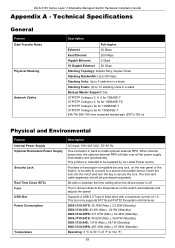
...supports FAT16 and FAT32 file system architectures DGS-3130-30TS: 30.76W (Max.), 23.20W (Standby) DGS-3130-30S: 82.4W (Max.), 43.9W (Standby) DGS-3130-30PS: 471.67W (Max.), 52.44W (Standby) DGS-3130-54TS: 50.62W (Max.), 38.67W (Standby) DGS-3130-54S: 131W (Max.), 68.7W (Standby) DGS-3130-54PS: 487.26W (Max.), 67...immovable device. When internal power fails, the optional external RPS will take over all the power supply immediately and automatically. DGS-3130 Series Layer 3 Stackable Managed Switch Hardware Installation Guide Appendix A - This product is off The IC Sensor detects the temperature ...
...supports FAT16 and FAT32 file system architectures DGS-3130-30TS: 30.76W (Max.), 23.20W (Standby) DGS-3130-30S: 82.4W (Max.), 43.9W (Standby) DGS-3130-30PS: 471.67W (Max.), 52.44W (Standby) DGS-3130-54TS: 50.62W (Max.), 38.67W (Standby) DGS-3130-54S: 131W (Max.), 68.7W (Standby) DGS-3130-54PS: 487.26W (Max.), 67...immovable device. When internal power fails, the optional external RPS will take over all the power supply immediately and automatically. DGS-3130 Series Layer 3 Stackable Managed Switch Hardware Installation Guide Appendix A - This product is off The IC Sensor detects the temperature ...
Quick Install Guide
Page 59
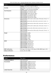
... mm (W) x 350 mm (D) x 44 mm (H), 19-inch, 1 U Rack-mount size DGS-3130-30TS: 2.98Kg DGS-3130-30S: 3.21Kg DGS-3130-30PS: 4.66Kg DGS-3130-54TS: 3.72Kg DGS-3130-54S: 4.52Kg DGS-3130-54PS: 5.14Kg DGS-3130-30TS: 900,546 Hours DGS-3130-30S: 487,153 Hours DGS-3130-30PS: 409,054 Hours DGS-3130-54TS: 478,258 Hours DGS-3130-54S: 520,861 Hours DGS-3130-54PS: 356,876 Hours CE Class A, FCC Class A, VCCI Class...
... mm (W) x 350 mm (D) x 44 mm (H), 19-inch, 1 U Rack-mount size DGS-3130-30TS: 2.98Kg DGS-3130-30S: 3.21Kg DGS-3130-30PS: 4.66Kg DGS-3130-54TS: 3.72Kg DGS-3130-54S: 4.52Kg DGS-3130-54PS: 5.14Kg DGS-3130-30TS: 900,546 Hours DGS-3130-30S: 487,153 Hours DGS-3130-30PS: 409,054 Hours DGS-3130-54TS: 478,258 Hours DGS-3130-54S: 520,861 Hours DGS-3130-54PS: 356,876 Hours CE Class A, FCC Class A, VCCI Class...
Quick Install Guide
Page 60
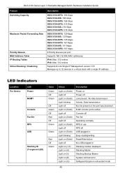
... Link present. DGS-3130 Series Layer 3 Stackable Managed Switch Hardware Installation Guide Feature Switching Capacity Maximum Packet Forwarding Rate Priority Queues MAC Address Table IP Routing Tables Virtual Stacking / Clustering Description DGS-3130-30TS: 168 Gbps DGS-3130-30S: 168 Gbps DGS-3130-30PS: 168 Gbps DGS-3130-54TS: 216 Gbps DGS-3130-54S: 216 Gbps DGS-3130-54PS: 216 Gbps DGS-3130-30TS: 125 Mpps DGS-3130-30S: 125 Mpps DGS-3130...
... Link present. DGS-3130 Series Layer 3 Stackable Managed Switch Hardware Installation Guide Feature Switching Capacity Maximum Packet Forwarding Rate Priority Queues MAC Address Table IP Routing Tables Virtual Stacking / Clustering Description DGS-3130-30TS: 168 Gbps DGS-3130-30S: 168 Gbps DGS-3130-30PS: 168 Gbps DGS-3130-54TS: 216 Gbps DGS-3130-54S: 216 Gbps DGS-3130-54PS: 216 Gbps DGS-3130-30TS: 125 Mpps DGS-3130-30S: 125 Mpps DGS-3130...

User Manual
Page 3
DGS-3130 Series Layer 3 Stackable Managed Switch Web UI Reference Guide Table of Contents Table of the User Interface...4 3. Management ...24 Command Logging ...24 User Accounts Settings ...24 Password Encryption ...25 Password Recovery ...26 Login Method ...26 SNMP...28 SNMP Global Settings ...29 SNMP Linkchange Trap Settings ...30 SNMP View Table Settings ...31 SNMP...
DGS-3130 Series Layer 3 Stackable Managed Switch Web UI Reference Guide Table of Contents Table of the User Interface...4 3. Management ...24 Command Logging ...24 User Accounts Settings ...24 Password Encryption ...25 Password Recovery ...26 Login Method ...26 SNMP...28 SNMP Global Settings ...29 SNMP Linkchange Trap Settings ...30 SNMP View Table Settings ...31 SNMP...

User Manual
Page 29
... of the Switch that can be displayed here. For example, 30/04/2015. For example, 18:30:30. To view the following window, click System > Time and SNTP > Clock Settings, as shown below : Parameter Time Date Description Enter the current time in the table. DGS-3130 Series Layer 3 Stackable Managed Switch Web UI Reference Guide...
... of the Switch that can be displayed here. For example, 30/04/2015. For example, 18:30:30. To view the following window, click System > Time and SNTP > Clock Settings, as shown below : Parameter Time Date Description Enter the current time in the table. DGS-3130 Series Layer 3 Stackable Managed Switch Web UI Reference Guide...

User Manual
Page 31
...will end. The default value is 60. Enter the number of this offset is 30, 60, 90 and 120. The range of minutes to accept the changes made. Select the time of this offset ...is 30, 60, 90 and 120. Select the month that summer time will end. The default value is ...during summer time. Select the month that summer time will end. Enter the year that the summer time will start. DGS-3130 Series Layer 3 Stackable Managed Switch Web UI Reference Guide Parameter To: Week of the Month To: Day of the ...
...will end. The default value is 60. Enter the number of this offset is 30, 60, 90 and 120. The range of minutes to accept the changes made. Select the time of this offset ...is 30, 60, 90 and 120. Select the month that summer time will end. The default value is ...during summer time. Select the month that summer time will end. Enter the year that the summer time will start. DGS-3130 Series Layer 3 Stackable Managed Switch Web UI Reference Guide Parameter To: Week of the Month To: Day of the ...

User Manual
Page 32
...Address Description Enter the IPv4 address of the SNTP server which provides the SNTP reference. Select the starting and ending time of the week. DGS-3130 Series Layer 3 Stackable Managed Switch Web UI Reference Guide Parameter SNTP State Poll Interval Description Select this option to display and configure the ... here. Time Range This window is used to enable or disable SNTP. Tick the End Week Day option to use this time profile from 30 to remove the specified entry. Click the Find button to add the SNTP server. Click the Add button to locate a specific entry based...
...Address Description Enter the IPv4 address of the SNTP server which provides the SNTP reference. Select the starting and ending time of the week. DGS-3130 Series Layer 3 Stackable Managed Switch Web UI Reference Guide Parameter SNTP State Poll Interval Description Select this option to display and configure the ... here. Time Range This window is used to enable or disable SNTP. Tick the End Week Day option to use this time profile from 30 to remove the specified entry. Click the Find button to add the SNTP server. Click the Add button to locate a specific entry based...

User Manual
Page 40
.... Tick this option to enable or disable the SNMP linkChange trap. Click the Apply button to accept the changes made . 30 To Port Trap Sending Trap State Description Select the Switch unit that will be configured are described below : Figure 4-8 SNMP ... trap is generated when the device recognizes that one of the communication links is down notifications. DGS-3130 Series Layer 3 Stackable Managed Switch Web UI Reference Guide Parameter Trap Global State SNMP Authentication Trap Port Link Up Port Link Down Coldstart Warmstart Description Select this option to enable or disable the ...
.... Tick this option to enable or disable the SNMP linkChange trap. Click the Apply button to accept the changes made . 30 To Port Trap Sending Trap State Description Select the Switch unit that will be configured are described below : Figure 4-8 SNMP ... trap is generated when the device recognizes that one of the communication links is down notifications. DGS-3130 Series Layer 3 Stackable Managed Switch Web UI Reference Guide Parameter Trap Global State SNMP Authentication Trap Port Link Up Port Link Down Coldstart Warmstart Description Select this option to enable or disable the ...

User Manual
Page 56
... ending IPv4 address that will be associated with this DHCP pool. Click the Apply button to accept the changes made . DGS-3130 Series Layer 3 Stackable Managed Switch Web UI Reference Guide Figure 4-30 DHCP Server Pool Settings (Edit Class) Window The fields that can be configured are described below : Parameter Option Type Description...
... ending IPv4 address that will be associated with this DHCP pool. Click the Apply button to accept the changes made . DGS-3130 Series Layer 3 Stackable Managed Switch Web UI Reference Guide Figure 4-30 DHCP Server Pool Settings (Edit Class) Window The fields that can be configured are described below : Parameter Option Type Description...

User Manual
Page 62
.... Enter the client DHCP Unique Identifier (DUID) here. The range is from 60 to requesting DHCPv6 clients here. This string can be 2592000 seconds (30 days). DGS-3130 Series Layer 3 Stackable Managed Switch Web UI Reference Guide Enter a page number and click the Go button to navigate to 28 characters long. 52 For...
.... Enter the client DHCP Unique Identifier (DUID) here. The range is from 60 to requesting DHCPv6 clients here. This string can be 2592000 seconds (30 days). DGS-3130 Series Layer 3 Stackable Managed Switch Web UI Reference Guide Enter a page number and click the Go button to navigate to 28 characters long. 52 For...