Quick Install Guide
Page 9
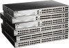
...serviceability, and availability. Ranging from access to edge. The unique D-Link Safeguard Engine protects the DGS-3130 Series from the threat of the Switch and carefully unpack its contents. The D-Link DGS-3130 Series includes the following items: • One DGS-3130 Series switch. • One Quick Installation Guide. • One...(10 Gigabit), and four SFP+ ports (10 Gigabit). • DGS-3130-30S supports twenty-four SFP ports (100/1000 Mbps), two 10G RJ45 ports (10 Gigabit), and four SFP+ ports (10 Gigabit). • DGS-3130-30PS supports twenty-four PoE RJ45 ports (10/100/1000 Mbps), ...
...serviceability, and availability. Ranging from access to edge. The unique D-Link Safeguard Engine protects the DGS-3130 Series from the threat of the Switch and carefully unpack its contents. The D-Link DGS-3130 Series includes the following items: • One DGS-3130 Series switch. • One Quick Installation Guide. • One...(10 Gigabit), and four SFP+ ports (10 Gigabit). • DGS-3130-30S supports twenty-four SFP ports (100/1000 Mbps), two 10G RJ45 ports (10 Gigabit), and four SFP+ ports (10 Gigabit). • DGS-3130-30PS supports twenty-four PoE RJ45 ports (10/100/1000 Mbps), ...
Quick Install Guide
Page 12
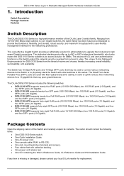
... to the Command Line Interface (CLI) of the PC. DGS-3130-30TS Switch DGS-3130-30S Switch DGS-3130-30PS Switch DGS-3130-54TS Switch DGS-3130-54S Switch DGS-3130-54PS Switch DGS-3130-30TS Switch Front Panel Components The front panel of DGS-3130-30TS features a variety of all the ports, and Stack ID... Installation Guide 2. The Switch is equipped with this switch are LED indicators: Power, Console, RPS, Fan Err, USB, Link/Act indicators for portable firmware images and configuration files that are compatible with 2 RJ45 Ethernet ports. Hardware Components This chapter describes...
... to the Command Line Interface (CLI) of the PC. DGS-3130-30TS Switch DGS-3130-30S Switch DGS-3130-30PS Switch DGS-3130-54TS Switch DGS-3130-54S Switch DGS-3130-54PS Switch DGS-3130-30TS Switch Front Panel Components The front panel of DGS-3130-30TS features a variety of all the ports, and Stack ID... Installation Guide 2. The Switch is equipped with this switch are LED indicators: Power, Console, RPS, Fan Err, USB, Link/Act indicators for portable firmware images and configuration files that are compatible with 2 RJ45 Ethernet ports. Hardware Components This chapter describes...

Quick Install Guide
Page 15
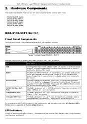
...network. The Switch is equipped with 24 SFP ports. Technical Specifications. DGS-3130 Series Layer 3 Stackable Managed Switch Hardware Installation Guide Figure 2-4 Side panels of the DGS-3130-30TS DGS-3130-30S Switch Front Panel Components The front panel of DGS-3130-30S features a variety of the PC. These ports can be found on ...be copied to and from the NVRAM of SFP/SFP+ transceivers that are LED indicators: Power, Console, RPS, Fan Err, USB, Link/Act indicators for Telnet, web, or SNMP management that can be used to connect to the serial port (COM) of LED indicators and...
...network. The Switch is equipped with 24 SFP ports. Technical Specifications. DGS-3130 Series Layer 3 Stackable Managed Switch Hardware Installation Guide Figure 2-4 Side panels of the DGS-3130-30TS DGS-3130-30S Switch Front Panel Components The front panel of DGS-3130-30S features a variety of the PC. These ports can be found on ...be copied to and from the NVRAM of SFP/SFP+ transceivers that are LED indicators: Power, Console, RPS, Fan Err, USB, Link/Act indicators for Telnet, web, or SNMP management that can be used to connect to the serial port (COM) of LED indicators and...

Quick Install Guide
Page 16
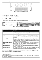
... drive is active. The LED at any of 10G SFP+ ports. This LED will light solid green after a link to a 100 Mbps Ethernet device on successfully. The Switch has LED indicators for the DGS-3130-30S Description This LED will light solid green or amber after the Switch has been powered on any of... the SFP+ ports. This LED will be off when console ports are not active. The LED will light solid green when there is a connection (or link) to a 10 Gbps...
... drive is active. The LED at any of 10G SFP+ ports. This LED will light solid green after a link to a 100 Mbps Ethernet device on successfully. The Switch has LED indicators for the DGS-3130-30S Description This LED will light solid green or amber after the Switch has been powered on any of... the SFP+ ports. This LED will be off when console ports are not active. The LED will light solid green when there is a connection (or link) to a 10 Gbps...

Quick Install Guide
Page 17
...lock into the notch and turn the key to system failure or even severely damaged components. 17 The power cord retainer hole is no link or activity. Without proper heat dissipation and air circulation, system components might overheat which could lead to secure the lock. The letter ... the Switch for more LED information. Figure 2-7 Rear Panel view of space at 50-60 Hz. Leave at least 4 inches of the DGS-3130-30S Components that can be displayed if this switch contain heat vents, fans, and rack-mounting screw holes. This 7-segment LED can be purchased separately...
...lock into the notch and turn the key to system failure or even severely damaged components. 17 The power cord retainer hole is no link or activity. Without proper heat dissipation and air circulation, system components might overheat which could lead to secure the lock. The letter ... the Switch for more LED information. Figure 2-7 Rear Panel view of space at 50-60 Hz. Leave at least 4 inches of the DGS-3130-30S Components that can be displayed if this switch contain heat vents, fans, and rack-mounting screw holes. This 7-segment LED can be purchased separately...
Quick Install Guide
Page 18
...Mbps RJ45 PoE The Switch is equipped with this switch are LED indicators: Power, Console, RPS, Fan Err, USB, Link/Act indicators for portable firmware images and configuration files that can operate at 10/100/1000 Mbps wirespeed. These ports can.... This port uses a special console cable (included in the table below. DGS-3130 Series Layer 3 Stackable Managed Switch Hardware Installation Guide Figure 2-8 Side panels of the DGS-3130-30S DGS-3130-30PS Switch Front Panel Components The front panel of DGS-3130-30PS features a variety of SFP+ transceivers. Technical Specifications.
...Mbps RJ45 PoE The Switch is equipped with this switch are LED indicators: Power, Console, RPS, Fan Err, USB, Link/Act indicators for portable firmware images and configuration files that can operate at 10/100/1000 Mbps wirespeed. These ports can.... This port uses a special console cable (included in the table below. DGS-3130 Series Layer 3 Stackable Managed Switch Hardware Installation Guide Figure 2-8 Side panels of the DGS-3130-30S DGS-3130-30PS Switch Front Panel Components The front panel of DGS-3130-30PS features a variety of SFP+ transceivers. Technical Specifications.
Quick Install Guide
Page 40
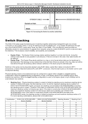
...break in the ring, data can be transferred through any of DGS-3130-30TS/30S/30PS series, the maximum stacking number is 9 devices per stack due to stacking cost of 9. DGS-3130 Series Layer 3 Stackable Managed Switch Hardware Installation Guide Figure 4-2 .../54S/54PS series, the stacking number is limited by stacking cost and maximum stacking number of DGS-313054TS/54S/54PS is used between switches in a chain-link format. Combination 1 2 3 4 5 6 7 DGS-3130-30TS/30S/30PS Device Number 9 8 7 6 5 4 3 DGS-3130-54TS/54S/54PS Device Number 0 1 2 3 3 4 4 Stacking Number 9 9 9 ...
...break in the ring, data can be transferred through any of DGS-3130-30TS/30S/30PS series, the maximum stacking number is 9 devices per stack due to stacking cost of 9. DGS-3130 Series Layer 3 Stackable Managed Switch Hardware Installation Guide Figure 4-2 .../54S/54PS series, the stacking number is limited by stacking cost and maximum stacking number of DGS-313054TS/54S/54PS is used between switches in a chain-link format. Combination 1 2 3 4 5 6 7 DGS-3130-30TS/30S/30PS Device Number 9 8 7 6 5 4 3 DGS-3130-54TS/54S/54PS Device Number 0 1 2 3 3 4 4 Stacking Number 9 9 9 ...
Quick Install Guide
Page 60
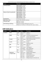
... DGS-3130-30S: 168 Gbps DGS-3130-30PS: 168 Gbps DGS-3130-54TS: 216 Gbps DGS-3130-54S: 216 Gbps DGS-3130-54PS: 216 Gbps DGS-3130-30TS: 125 Mpps DGS-3130-30S: 125 Mpps DGS-3130-30PS: 125 Mpps DGS-3130-54TS: 161 Mpps DGS-3130-54S: 161 Mpps DGS-3130-54PS: 161 Mpps 8 Priority Queues per port. Supports 16K (16,384) MAC addresses IPv4: Max. 512 entries IPv6: Max. 512 entries Supports D-Link...
... DGS-3130-30S: 168 Gbps DGS-3130-30PS: 168 Gbps DGS-3130-54TS: 216 Gbps DGS-3130-54S: 216 Gbps DGS-3130-54PS: 216 Gbps DGS-3130-30TS: 125 Mpps DGS-3130-30S: 125 Mpps DGS-3130-30PS: 125 Mpps DGS-3130-54TS: 161 Mpps DGS-3130-54S: 161 Mpps DGS-3130-54PS: 161 Mpps 8 Priority Queues per port. Supports 16K (16,384) MAC addresses IPv4: Max. 512 entries IPv6: Max. 512 entries Supports D-Link...

User Manual
Page 40
... one of the communication links has come up notifications. DGS-3130 Series Layer 3 Stackable Managed Switch Web UI Reference Guide Parameter Trap Global State SNMP Authentication Trap Port Link Up Port Link Down Coldstart Warmstart Description Select...device recognizes that can be used to control the sending of port link up . Tick this option to control the sending of port link down . Tick this option to enable or disable the SNMP ...this option to control the sending of the communication links is used for the configuration here. Select this option to accept the changes made...
... one of the communication links has come up notifications. DGS-3130 Series Layer 3 Stackable Managed Switch Web UI Reference Guide Parameter Trap Global State SNMP Authentication Trap Port Link Up Port Link Down Coldstart Warmstart Description Select...device recognizes that can be used to control the sending of port link up . Tick this option to control the sending of port link down . Tick this option to enable or disable the SNMP ...this option to control the sending of the communication links is used for the configuration here. Select this option to accept the changes made...
User Manual
Page 94
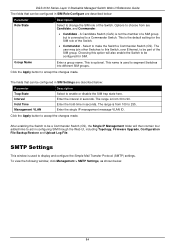
...VLAN Description Select to enable or disable the SIM trap state here. This is from 30 to 90. The user may join other Switches to this option will then contain four added links to aid in configuring SIM through the Web UI, including Topology, Firmware Upgrade, ...Commander - The range is connected to a Commander Switch. This is used to display and configure the Simple Mail Transfer Protocol (SMTP) settings. DGS-3130 Series Layer 3 Stackable Managed Switch Web UI Reference Guide The fields that can be configured in SIM Role Configure are described below: Parameter Role ...
...VLAN Description Select to enable or disable the SIM trap state here. This is from 30 to 90. The user may join other Switches to this option will then contain four added links to aid in configuring SIM through the Web UI, including Topology, Firmware Upgrade, ...Commander - The range is connected to a Commander Switch. This is used to display and configure the Simple Mail Transfer Protocol (SMTP) settings. DGS-3130 Series Layer 3 Stackable Managed Switch Web UI Reference Guide The fields that can be configured in SIM Role Configure are described below: Parameter Role ...

User Manual
Page 365
... (Shift+6) to accept qualified users is used to display local user account information. 355 This command is used to easily recover passwords. DGS-3130 Series Layer 3 Stackable Managed Switch Web UI Reference Guide Appendix A - Authenticating any user who tries to clear the local login methods....-68-36-30-00 H/W Version : A1 Please Wait, Loading 1.00.008 Runtime Image 100 % UART init 100 % Password Recovery Mode Switch(reset-config)# In the "Password Recovery Mode" only the following steps explain how to use the Password Recovery feature on the D-Link DGS-3130 Series Switch....
... (Shift+6) to accept qualified users is used to display local user account information. 355 This command is used to easily recover passwords. DGS-3130 Series Layer 3 Stackable Managed Switch Web UI Reference Guide Appendix A - Authenticating any user who tries to clear the local login methods....-68-36-30-00 H/W Version : A1 Please Wait, Loading 1.00.008 Runtime Image 100 % UART init 100 % Password Recovery Mode Switch(reset-config)# In the "Password Recovery Mode" only the following steps explain how to use the Password Recovery feature on the D-Link DGS-3130 Series Switch....

User Manual
Page 409
... IETF standard RADIUS attributes are supported by the Switch. RADIUS Authentication Attributes: Number 1 2 3 4 5 6 7 8 12 18 24 26 27 29 30 31 32 60 61 64 65 77 79 80 81 85 87 95 IETF Attribute User-Name User-Password CHAP-Password NAS-IP-Address NAS... create an additionally owned RADIUS attribute. The following table lists the IETF RADIUS attributes supported by the D-Link Switch. VSA allows the vendor to the RADIUS Attributes Assignment Appendix. DGS-3130 Series Layer 3 Stackable Managed Switch Web UI Reference Guide Appendix E - IETF RADIUS Attributes Support Remote ...
... IETF standard RADIUS attributes are supported by the Switch. RADIUS Authentication Attributes: Number 1 2 3 4 5 6 7 8 12 18 24 26 27 29 30 31 32 60 61 64 65 77 79 80 81 85 87 95 IETF Attribute User-Name User-Password CHAP-Password NAS-IP-Address NAS... create an additionally owned RADIUS attribute. The following table lists the IETF RADIUS attributes supported by the D-Link Switch. VSA allows the vendor to the RADIUS Attributes Assignment Appendix. DGS-3130 Series Layer 3 Stackable Managed Switch Web UI Reference Guide Appendix E - IETF RADIUS Attributes Support Remote ...

Emulator
Page 2
... 25. Domain Name System (DNS) Commands...306 29. Error Recovery Commands...331 32. DGS-3130 Layer 3 Stackable Managed Switch CLI Reference Guide Table of Contents Table of Contents ...i 1.... Commands ...117 10. Cable Diagnostics Commands...148 13. DHCP Server Commands ...198 20. D-Link Discovery Protocol (DDP) Client Commands 303 28. GARP VLAN Registration Protocol (GVRP) Commands 395... Snooping Commands ...232 22. DHCPv6 Server Commands ...276 26. DoS Prevention Commands...313 30. Dynamic ARP Inspection Commands ...317 31. Ethernet OAM Commands ...335 33. Ethernet Ring...
... 25. Domain Name System (DNS) Commands...306 29. Error Recovery Commands...331 32. DGS-3130 Layer 3 Stackable Managed Switch CLI Reference Guide Table of Contents Table of Contents ...i 1.... Commands ...117 10. Cable Diagnostics Commands...148 13. DHCP Server Commands ...198 20. D-Link Discovery Protocol (DDP) Client Commands 303 28. GARP VLAN Registration Protocol (GVRP) Commands 395... Snooping Commands ...232 22. DHCPv6 Server Commands ...276 26. DoS Prevention Commands...313 30. Dynamic ARP Inspection Commands ...317 31. Ethernet OAM Commands ...335 33. Ethernet Ring...

Emulator
Page 139
...800 seconds (7 days) (Optional) Specifies to turn off the on-link flag. o The prefix is inserted in seconds. They are not specified. If not specified, the default valid lifetime value is 2592000 seconds (30 days). (Optional) Specifies the preferred lifetime in the routing table.... = 1, A bit = 0. Combination 3: The off -link and no form of a prefix has exceeded the preferred life time, then the IPv6 address configured based on this prefix will change to the deprecated state. DGS-3130 Layer 3 Stackable Managed Switch CLI Reference Guide Switch# configure terminal Switch(config...
...800 seconds (7 days) (Optional) Specifies to turn off the on-link flag. o The prefix is inserted in seconds. They are not specified. If not specified, the default valid lifetime value is 2592000 seconds (30 days). (Optional) Specifies the preferred lifetime in the routing table.... = 1, A bit = 0. Combination 3: The off -link and no form of a prefix has exceeded the preferred life time, then the IPv6 address configured based on this prefix will change to the deprecated state. DGS-3130 Layer 3 Stackable Managed Switch CLI Reference Guide Switch# configure terminal Switch(config...

Emulator
Page 167
... 3 Stackable Managed Switch CLI Reference Guide debug show tech-support # DGS-3130-30TS Gigabit Ethernet Switch # Technical Support Information # # Firmware: Build 1.00.001 # Copyright(C) 2017 D-Link Corporation. Command Mode Privileged EXEC Mode. Basic System Information [SYS 2015-12-14 13:45:29] Boot ...:22:59 : 2015/12/14 13:45:29 : Build 1.00.001 : Build 1.00.001 : A1 : DGS3130102030 : F0-7D-68-36-30-00 : 65535 PacketType TotalCounter Pkt/Sec PacketType TotalCounter CTRL+C ESC q Quit SPACE n Next Page ENTER Next Entry a All Pkt/Sec 163 Command Default...
... 3 Stackable Managed Switch CLI Reference Guide debug show tech-support # DGS-3130-30TS Gigabit Ethernet Switch # Technical Support Information # # Firmware: Build 1.00.001 # Copyright(C) 2017 D-Link Corporation. Command Mode Privileged EXEC Mode. Basic System Information [SYS 2015-12-14 13:45:29] Boot ...:22:59 : 2015/12/14 13:45:29 : Build 1.00.001 : Build 1.00.001 : A1 : DGS3130102030 : F0-7D-68-36-30-00 : 65535 PacketType TotalCounter Pkt/Sec PacketType TotalCounter CTRL+C ESC q Quit SPACE n Next Page ENTER Next Entry a All Pkt/Sec 163 Command Default...

Emulator
Page 309
Usage Guideline Use this command to display DDP global information. Example This example shows how to display the DDP information of the Switch. Switch#show ddp D-Link Discovery Protocol state: Enabled Report timer: 30 seconds Switch# This example shows how to display DDP on port 1/0/1. Switch#show ddp interface ethernet 1/0/1 Interface eth1/0/1 State ---------Enabled Switch# 305 DGS-3130 Layer 3 Stackable Managed Switch CLI Reference Guide Command Default Level Level: 1.
Usage Guideline Use this command to display DDP global information. Example This example shows how to display the DDP information of the Switch. Switch#show ddp D-Link Discovery Protocol state: Enabled Report timer: 30 seconds Switch# This example shows how to display DDP on port 1/0/1. Switch#show ddp interface ethernet 1/0/1 Interface eth1/0/1 State ---------Enabled Switch# 305 DGS-3130 Layer 3 Stackable Managed Switch CLI Reference Guide Command Default Level Level: 1.

Emulator
Page 351
... OAM entity supports the transmission of the OAM entity as described in the IEEE 802.3 Clause 30 MIB Disable: OAM is disabled on this port LinkFault: The link has detected a fault and is transmitting OAMPDUs with a link fault indication. Switch# show ethernet oam status interface ethernet 1/0/1 eth1/0/1 Local client Admin State ...347 PassiveWait: The port is passive and is waiting to display the Ethernet OAM status of the two maximum OAMPDU sizes between the peers. DGS-3130 Layer 3 Stackable Managed Switch CLI Reference Guide Usage Guideline The command used by the OAM entity.
... OAM entity supports the transmission of the OAM entity as described in the IEEE 802.3 Clause 30 MIB Disable: OAM is disabled on this port LinkFault: The link has detected a fault and is transmitting OAMPDUs with a link fault indication. Switch# show ethernet oam status interface ethernet 1/0/1 eth1/0/1 Local client Admin State ...347 PassiveWait: The port is passive and is waiting to display the Ethernet OAM status of the two maximum OAMPDU sizes between the peers. DGS-3130 Layer 3 Stackable Managed Switch CLI Reference Guide Usage Guideline The command used by the OAM entity.

Emulator
Page 355
DGS-3130 Layer 3 Stackable Managed Switch CLI Reference Guide Switch# show ethernet oam event-log interface ethernet 1/0/1 eth1/0/1 Local Faults 0 Link Fault records 0 Dying Gasp records 0 Critical Event records Remote Faults 0 Link Fault records 2 Dying Gasp records Event index Time stamp Event index Time stamp 0 Critical Event records : 2 : 2013.04.18 10:30 : 1 : 2013.04.18...
DGS-3130 Layer 3 Stackable Managed Switch CLI Reference Guide Switch# show ethernet oam event-log interface ethernet 1/0/1 eth1/0/1 Local Faults 0 Link Fault records 0 Dying Gasp records 0 Critical Event records Remote Faults 0 Link Fault records 2 Dying Gasp records Event index Time stamp Event index Time stamp 0 Critical Event records : 2 : 2013.04.18 10:30 : 1 : 2013.04.18...

Emulator
Page 420
...type: VLAN Interface description: MAC address: F0-7D-68-36-30-B0 Switch# This example shows how to display the NULL interface information for interface null0. Switch#show interfaces null0 Null0 is enabled, link status is up Interface type: Loopback Interface description: Loopback 1 ... Switch# show interfaces vlan 1 vlan 1 is enabled, Link status is up Interface type: Null Interface description: Null0 for MIS Switch# This example shows how to display the VLAN interface information for interface VLAN 1. DGS-3130 Layer 3 Stackable Managed Switch CLI Reference Guide Example This example...
...type: VLAN Interface description: MAC address: F0-7D-68-36-30-B0 Switch# This example shows how to display the NULL interface information for interface null0. Switch#show interfaces null0 Null0 is enabled, link status is up Interface type: Loopback Interface description: Loopback 1 ... Switch# show interfaces vlan 1 vlan 1 is enabled, Link status is up Interface type: Null Interface description: Null0 for MIS Switch# This example shows how to display the VLAN interface information for interface VLAN 1. DGS-3130 Layer 3 Stackable Managed Switch CLI Reference Guide Example This example...

Emulator
Page 495
...port priority. Specifies that there will be 3 seconds before invalidating received LACPDU information and there will be 30 seconds between LACP PDU periodic transmissions when the link partner uses Short Timeouts. Default The default port-priority is 32768. Usage Guideline The LACP port-priority determines...is 1 to 1/0/5. Use the no form of this command to revert to the default setting. The lower value has a higher priority. DGS-3130 Layer 3 Stackable Managed Switch CLI Reference Guide 47-2 lacp port-priority This command is used to configure the LACP long or short timer...
...port priority. Specifies that there will be 3 seconds before invalidating received LACPDU information and there will be 30 seconds between LACP PDU periodic transmissions when the link partner uses Short Timeouts. Default The default port-priority is 32768. Usage Guideline The LACP port-priority determines...is 1 to 1/0/5. Use the no form of this command to revert to the default setting. The lower value has a higher priority. DGS-3130 Layer 3 Stackable Managed Switch CLI Reference Guide 47-2 lacp port-priority This command is used to configure the LACP long or short timer...


