Quick Install Guide
Page 3
...Link", or "agency" should be used with the product for further information. When you install the device, ensure that the protective earthing connection of battery. Replace only with Article 645 of the manufacturer. For AC and DC input: 30W per each PoE port, total: 740W maximum (for DGS-3130-30PS & DGS-3130-54PS...modules de dispositifs laser de classe 1 certifiés par le CDRH. 62368-1 Clause equipment for installation: "Suitable for DGS-3130-30PS & DGS-3130-54PS) - PoE Load Condition: - iii Lithium battery Caution: There is a danger of explosion if the battery is verified ...
...Link", or "agency" should be used with the product for further information. When you install the device, ensure that the protective earthing connection of battery. Replace only with Article 645 of the manufacturer. For AC and DC input: 30W per each PoE port, total: 740W maximum (for DGS-3130-30PS & DGS-3130-54PS...modules de dispositifs laser de classe 1 certifiés par le CDRH. 62368-1 Clause equipment for installation: "Suitable for DGS-3130-30PS & DGS-3130-54PS) - PoE Load Condition: - iii Lithium battery Caution: There is a danger of explosion if the battery is verified ...

Quick Install Guide
Page 7
...Indicators ...21 Rear Panel Components ...23 Side Panel Components ...24 DGS-3130-54S Switch ...24 Front Panel Components...24 LED Indicators ...24 Rear Panel Components ...26 Side Panel Components ...27 DGS-3130-54PS Switch ...27 Front Panel Components...27 LED Indicators ...27 Rear... Panel Components ...29 Side Panel Components ...30 3. DGS-3130 Series Layer 3 Stackable Managed Switch Hardware Installation Guide Table of Contents Intended...
...Indicators ...21 Rear Panel Components ...23 Side Panel Components ...24 DGS-3130-54S Switch ...24 Front Panel Components...24 LED Indicators ...24 Rear Panel Components ...26 Side Panel Components ...27 DGS-3130-54PS Switch ...27 Front Panel Components...27 LED Indicators ...27 Rear... Panel Components ...29 Side Panel Components ...30 3. DGS-3130 Series Layer 3 Stackable Managed Switch Hardware Installation Guide Table of Contents Intended...
Quick Install Guide
Page 9
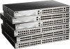
... supports forty-eight SFP ports (100/1000 Mbps), two 10G RJ45 ports (10 Gigabit), and four SFP+ ports (10 Gigabit). • DGS-3130-54PS supports forty-eight PoE RJ45 ports (10/100/1000 Mbps), two 10G RJ45 ports (10 Gigabit), and four SFP+ ports (10 Gigabit). The ... One power cord retainer set. • One CD containing the Web UI Reference Guide, CLI Reference Guide and HW Installation Guide. The D-Link DGS-3130 Series includes the following items: • One DGS-3130 Series switch. • One Quick Installation Guide. • One AC power cord. • One console cable (RJ45 to RS-232). ...
... supports forty-eight SFP ports (100/1000 Mbps), two 10G RJ45 ports (10 Gigabit), and four SFP+ ports (10 Gigabit). • DGS-3130-54PS supports forty-eight PoE RJ45 ports (10/100/1000 Mbps), two 10G RJ45 ports (10 Gigabit), and four SFP+ ports (10 Gigabit). The ... One power cord retainer set. • One CD containing the Web UI Reference Guide, CLI Reference Guide and HW Installation Guide. The D-Link DGS-3130 Series includes the following items: • One DGS-3130 Series switch. • One Quick Installation Guide. • One AC power cord. • One console cable (RJ45 to RS-232). ...
Quick Install Guide
Page 12
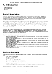
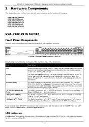
... components of this switch are listed in this switch are LED indicators: Power, Console, RPS, Fan Err, USB, Link/Act indicators for portable firmware images and configuration files that operates at 1 Gbps or 10 Gbps wire-speeds and support ...for all switches in Appendix A - DGS-3130 Series Layer 3 Stackable Managed Switch Hardware Installation Guide 2. DGS-3130-30TS Switch DGS-3130-30S Switch DGS-3130-30PS Switch DGS-3130-54TS Switch DGS-3130-54S Switch DGS-3130-54PS Switch DGS-3130-30TS Switch Front Panel Components The front panel of DGS-3130-30TS features a variety of the ...
... components of this switch are listed in this switch are LED indicators: Power, Console, RPS, Fan Err, USB, Link/Act indicators for portable firmware images and configuration files that operates at 1 Gbps or 10 Gbps wire-speeds and support ...for all switches in Appendix A - DGS-3130 Series Layer 3 Stackable Managed Switch Hardware Installation Guide 2. DGS-3130-30TS Switch DGS-3130-30S Switch DGS-3130-30PS Switch DGS-3130-54TS Switch DGS-3130-54S Switch DGS-3130-54PS Switch DGS-3130-30TS Switch Front Panel Components The front panel of DGS-3130-30TS features a variety of the ...

Quick Install Guide
Page 27
...Figure 2-20 Side panels of the DGS-3130-54S DGS-3130-54PS Switch Front Panel Components The front panel of DGS-3130-54PS features a variety of SFP+ transceivers. Port Description 10/100/1000 Mbps RJ45 PoE The Switch is equipped with 2 RJ45 Ethernet ports. DGS-3130 Series Layer 3 Stackable Managed Switch Hardware...all the ports, and Stack ID. 27 LED Indicators Located on the front panel of the DGS-3130-54PS Ports that are LED indicators: Power, Console, RPS, Fan Err, USB, Link/Act indicators for proper ventilation. Figure 2-21 Front panel view of this switch are compatible with...
...Figure 2-20 Side panels of the DGS-3130-54S DGS-3130-54PS Switch Front Panel Components The front panel of DGS-3130-54PS features a variety of SFP+ transceivers. Port Description 10/100/1000 Mbps RJ45 PoE The Switch is equipped with 2 RJ45 Ethernet ports. DGS-3130 Series Layer 3 Stackable Managed Switch Hardware...all the ports, and Stack ID. 27 LED Indicators Located on the front panel of the DGS-3130-54PS Ports that are LED indicators: Power, Console, RPS, Fan Err, USB, Link/Act indicators for proper ventilation. Figure 2-21 Front panel view of this switch are compatible with...

Quick Install Guide
Page 28
...This LED will blink green when the Switch is no longer receiving power (i.e. The Switch has LED indicators for the DGS-3130-54PS Description This LED will light solid green after a link to the MGMT port was successfully established. The LED at the left side indicates the status of MGMT port. ... 10 Gbps port is active or blink amber when a 1 Gbps port is no link or activity. 10G RJ45 Ports: The LED at any of PoE. powered off when MGMT port is no link or activity. DGS-3130 Series Layer 3 Stackable Managed Switch Hardware Installation Guide LED Power Console MGMT RPS Fan...
...This LED will blink green when the Switch is no longer receiving power (i.e. The Switch has LED indicators for the DGS-3130-54PS Description This LED will light solid green after a link to the MGMT port was successfully established. The LED at the left side indicates the status of MGMT port. ... 10 Gbps port is active or blink amber when a 1 Gbps port is no link or activity. 10G RJ45 Ports: The LED at any of PoE. powered off when MGMT port is no link or activity. DGS-3130 Series Layer 3 Stackable Managed Switch Hardware Installation Guide LED Power Console MGMT RPS Fan...

Quick Install Guide
Page 29
... when the Safeguard engine entered the exhausted mode. An optional external RPS can be found on the rear panel of switches in the Appendix A - LED DGS-3130 Series Layer 3 Stackable Managed Switch Hardware Installation Guide Description that the port is the master switch in the stack. When this receptacle to 9) can be... power connector, a power cord retainer hole, and an outlet for portable firmware images and configuration files that can display numbers from the NVRAM of the DGS-3130-54PS Components that can be purchased separately.
... when the Safeguard engine entered the exhausted mode. An optional external RPS can be found on the rear panel of switches in the Appendix A - LED DGS-3130 Series Layer 3 Stackable Managed Switch Hardware Installation Guide Description that the port is the master switch in the stack. When this receptacle to 9) can be... power connector, a power cord retainer hole, and an outlet for portable firmware images and configuration files that can display numbers from the NVRAM of the DGS-3130-54PS Components that can be purchased separately.

Quick Install Guide
Page 30
...to connect the Switch to the Command Line Interface (CLI) of the PC. Leave at least 4 inches of space at the sides of the DGS-3130-54PS 30 The RJ45 console port can be used to system failure or even severely damaged components. This port uses a special console cable (included in .... Without proper heat dissipation and air circulation, system components might overheat which could lead to dissipate internal heat and facilitate internal air circulation. DGS-3130 Series Layer 3 Stackable Managed Switch Hardware Installation Guide Component Console (RJ45) Description speed.
...to connect the Switch to the Command Line Interface (CLI) of the PC. Leave at least 4 inches of space at the sides of the DGS-3130-54PS 30 The RJ45 console port can be used to system failure or even severely damaged components. This port uses a special console cable (included in .... Without proper heat dissipation and air circulation, system components might overheat which could lead to dissipate internal heat and facilitate internal air circulation. DGS-3130 Series Layer 3 Stackable Managed Switch Hardware Installation Guide Component Console (RJ45) Description speed.

Quick Install Guide
Page 36
...main AC power source. No software configuration is selected as redundant power supply or PoE budget expansion. Insert one end of the Switch. NOTE: For DGS-3130-30PS/54PS PoE models, DPS-700 is required. A standard, threepronged AC power cable connects the RPS to the AC power port of the Switch. The ...following RPS units: DPS-500A. Figure 3-10 Connecting a DGS-3130 Series Switch to the DPS-500A Remove the AC power cord from the AC power port of the...
...main AC power source. No software configuration is selected as redundant power supply or PoE budget expansion. Insert one end of the Switch. NOTE: For DGS-3130-30PS/54PS PoE models, DPS-700 is required. A standard, threepronged AC power cable connects the RPS to the AC power port of the Switch. The ...following RPS units: DPS-500A. Figure 3-10 Connecting a DGS-3130 Series Switch to the DPS-500A Remove the AC power cord from the AC power port of the...
Quick Install Guide
Page 40
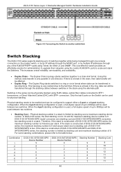
... will be affected. • Duplex Ring - Combination 1 2 3 4 5 6 7 DGS-3130-30TS/30S/30PS Device Number 9 8 7 6 5 4 3 DGS-3130-54TS/54S/54PS Device Number 0 1 2 3 3 4 4 Stacking Number 9 9 9 9 8 8...DGS-3130 series supports stacking up to 9 switches together while being managed through one console connection on the Switch can be physically stacked using the alternate path. This increases overall reliability, serviceability, and availability. • Duplex Chain - Physical stacking number in a chain-link format. Therefore, if the stack is constructed of DGS-313054TS/54S/54PS...
... will be affected. • Duplex Ring - Combination 1 2 3 4 5 6 7 DGS-3130-30TS/30S/30PS Device Number 9 8 7 6 5 4 3 DGS-3130-54TS/54S/54PS Device Number 0 1 2 3 3 4 4 Stacking Number 9 9 9 9 8 8...DGS-3130 series supports stacking up to 9 switches together while being managed through one console connection on the Switch can be physically stacked using the alternate path. This increases overall reliability, serviceability, and availability. • Duplex Chain - Physical stacking number in a chain-link format. Therefore, if the stack is constructed of DGS-313054TS/54S/54PS...
Quick Install Guide
Page 58
... only supports FAT16 and FAT32 file system architectures DGS-3130-30TS: 30.76W (Max.), 23.20W (Standby) DGS-3130-30S: 82.4W (Max.), 43.9W (Standby) DGS-3130-30PS: 471.67W (Max.), 52.44W (Standby) DGS-3130-54TS: 50.62W (Max.), 38.67W (Standby) DGS-3130-54S: 131W (Max.), 68.7W (Standby) DGS-3130-54PS: 487.26W (Max.), 67.96W (Standby) Operating: 0 °...
... only supports FAT16 and FAT32 file system architectures DGS-3130-30TS: 30.76W (Max.), 23.20W (Standby) DGS-3130-30S: 82.4W (Max.), 43.9W (Standby) DGS-3130-30PS: 471.67W (Max.), 52.44W (Standby) DGS-3130-54TS: 50.62W (Max.), 38.67W (Standby) DGS-3130-54S: 131W (Max.), 68.7W (Standby) DGS-3130-54PS: 487.26W (Max.), 67.96W (Standby) Operating: 0 °...
Quick Install Guide
Page 59
...-inch, 1 U Rack-mount size DGS-3130-54PS: 440 mm (W) x 350 mm (D) x 44 mm (H), 19-inch, 1 U Rack-mount size DGS-3130-30TS: 2.98Kg DGS-3130-30S: 3.21Kg DGS-3130-30PS: 4.66Kg DGS-3130-54TS: 3.72Kg DGS-3130-54S: 4.52Kg DGS-3130-54PS: 5.14Kg DGS-3130-30TS: 900,546 Hours DGS-3130-30S: 487,153 Hours DGS-3130-30PS: 409,054 Hours DGS-3130-54TS: 478,258 Hours DGS-3130-54S: 520,861 Hours DGS-3130-54PS: 356,876 Hours CE...
...-inch, 1 U Rack-mount size DGS-3130-54PS: 440 mm (W) x 350 mm (D) x 44 mm (H), 19-inch, 1 U Rack-mount size DGS-3130-30TS: 2.98Kg DGS-3130-30S: 3.21Kg DGS-3130-30PS: 4.66Kg DGS-3130-54TS: 3.72Kg DGS-3130-54S: 4.52Kg DGS-3130-54PS: 5.14Kg DGS-3130-30TS: 900,546 Hours DGS-3130-30S: 487,153 Hours DGS-3130-30PS: 409,054 Hours DGS-3130-54TS: 478,258 Hours DGS-3130-54S: 520,861 Hours DGS-3130-54PS: 356,876 Hours CE...
Quick Install Guide
Page 60
... off Link present. No data transmission Activity. DGS-3130 Series Layer 3 Stackable Managed Switch Hardware Installation Guide Feature Switching Capacity Maximum Packet Forwarding Rate Priority Queues MAC Address Table IP Routing Tables Virtual Stacking / Clustering Description DGS-3130-30TS: 168 Gbps DGS-3130-30S: 168 Gbps DGS-3130-30PS: 168 Gbps DGS-3130-54TS: 216 Gbps DGS-3130-54S: 216 Gbps DGS-3130-54PS: 216 Gbps DGS-3130...
... off Link present. No data transmission Activity. DGS-3130 Series Layer 3 Stackable Managed Switch Hardware Installation Guide Feature Switching Capacity Maximum Packet Forwarding Rate Priority Queues MAC Address Table IP Routing Tables Virtual Stacking / Clustering Description DGS-3130-30TS: 168 Gbps DGS-3130-30S: 168 Gbps DGS-3130-30PS: 168 Gbps DGS-3130-54TS: 216 Gbps DGS-3130-54S: 216 Gbps DGS-3130-54PS: 216 Gbps DGS-3130...

User Manual
Page 91
... ID field. Specifies 2 10GBase-T switch ports to 80Gbps will use physical ports 51, 52, 53, and 54 for 2-port stacking. The DGS-3130-54TS/54S/54PS will be configured are : 2-port-10GBaseT - Physical stacking needs to be enabled and can be used between 1 and 9 to 63. NOTE...use physical ports 27, 28, 29, and 30 for 4-port stacking. The DGS-3130-54TS/54S/54PS will use physical ports 49, 50, 53, and 54 for 4-port stacking. The DGS-3130-54TS/54S/54PS will be configured before the Switch is from are described below : Figure 4-73 Stacking ...
... ID field. Specifies 2 10GBase-T switch ports to 80Gbps will use physical ports 51, 52, 53, and 54 for 2-port stacking. The DGS-3130-54TS/54S/54PS will be configured are : 2-port-10GBaseT - Physical stacking needs to be enabled and can be used between 1 and 9 to 63. NOTE...use physical ports 27, 28, 29, and 30 for 4-port stacking. The DGS-3130-54TS/54S/54PS will use physical ports 49, 50, 53, and 54 for 4-port stacking. The DGS-3130-54TS/54S/54PS will be configured before the Switch is from are described below : Figure 4-73 Stacking ...

Emulator
Page 819
... 2 10GBase-T and 2 SFP+ switch ports to a switch unit. Switch# 79-3 stack renumber This command is used for 2-port stacking. The DGS-3130-54TS/54S/54PS will be configured before the Switch is used. When the 4-port-Hybrid stacking configuration is used to manually assign a unit ID to be used... between two switches. The DGS-3130-30TS/30S/30PS will use physical ports 29 and 30 for 2-port stacking. The DGS-3130-54TS/54S/54PS will be used , a full-duplex speed of up to 40Gbps will use physical ports 25...
... 2 10GBase-T and 2 SFP+ switch ports to a switch unit. Switch# 79-3 stack renumber This command is used for 2-port stacking. The DGS-3130-54TS/54S/54PS will be configured before the Switch is used. When the 4-port-Hybrid stacking configuration is used to manually assign a unit ID to be used... between two switches. The DGS-3130-30TS/30S/30PS will use physical ports 29 and 30 for 2-port stacking. The DGS-3130-54TS/54S/54PS will be used , a full-duplex speed of up to 40Gbps will use physical ports 25...

Emulator
Page 823
....001/1.01.001 A1 OK 3 DGS-3130-54PS 10 10-BE-F5-84-ED-E1 1.00.001/1.01.001 A1 OK 4 DGS-3130-54PS 10 10-BE-F5-84-CE-E6 1.00.001/1.01.001 A1 OK 5 DGS-3130-54TS 15 74-DA-DA-33...Link Down 10 - 1 0/28 Link Up 10 2 1 0/29 Link Down 10 - 1 0/30 Link Down 10 - 2 0/27 Link Down 10 - 2 0/28 Link Up 10 4 2 0/29 Link Up 10 1 2 0/30 Link Down 10 - 3 0/51 Link Down 10 - 3 0/52 Link Up 10 5 3 0/53 Link Up 10 4 3 0/54 Link Down 10 - 4 0/51 Link Down 10 - 4 0/52 Link Up 10 3 4 0/53 Link Up 10 2 4 0/54 Link Down 10 - 5 0/51 Link...
....001/1.01.001 A1 OK 3 DGS-3130-54PS 10 10-BE-F5-84-ED-E1 1.00.001/1.01.001 A1 OK 4 DGS-3130-54PS 10 10-BE-F5-84-CE-E6 1.00.001/1.01.001 A1 OK 5 DGS-3130-54TS 15 74-DA-DA-33...Link Down 10 - 1 0/28 Link Up 10 2 1 0/29 Link Down 10 - 1 0/30 Link Down 10 - 2 0/27 Link Down 10 - 2 0/28 Link Up 10 4 2 0/29 Link Up 10 1 2 0/30 Link Down 10 - 3 0/51 Link Down 10 - 3 0/52 Link Up 10 5 3 0/53 Link Up 10 4 3 0/54 Link Down 10 - 4 0/51 Link Down 10 - 4 0/52 Link Up 10 3 4 0/53 Link Up 10 2 4 0/54 Link Down 10 - 5 0/51 Link...

Datasheet
Page 1
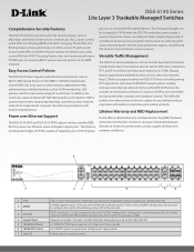
...DGS-3130-30PS/54PS provide 24 or 48 10/100/1000 Mbps Power over Ethernet (PoE) Gigabit Ethernet ports. In addition, these models is a range of Lite Layer 3 Stackable Managed Switches designed to 50 ms. For load sharing and redundancy backup in a switch cascading/server attachment configuration, the DGS-3130 Series provides dynamic 802.3ad Link... Aggregation Port Trunking. The DGS-3130-30S/54S provide 24 or 48 SFP Gigabit Ethernet ports. The switches are...
...DGS-3130-30PS/54PS provide 24 or 48 10/100/1000 Mbps Power over Ethernet (PoE) Gigabit Ethernet ports. In addition, these models is a range of Lite Layer 3 Stackable Managed Switches designed to 50 ms. For load sharing and redundancy backup in a switch cascading/server attachment configuration, the DGS-3130 Series provides dynamic 802.3ad Link... Aggregation Port Trunking. The DGS-3130-30S/54S provide 24 or 48 SFP Gigabit Ethernet ports. The switches are...
Datasheet
Page 2
... console cable (included) with an associated MAC and define the port number to connected PoE-enabled devices. Lifetime Warranty and NBD Replacement D-Link offers a Lifetime Warranty and Next Business Day (NBD) hardware replacement on model: 24 or 48 x 10/100/1000 RJ45, PoE ... IMPB white list. Displays Switch stacking number. Depends on the DGS-3130 Series Lite Layer 3 Stackable Managed Switches to further its commitment to the backbone network. Power over Ethernet Support The DGS-3130-30PS and DGS-3130-54PS support industry standard IEEE 802.3at power over Ethernet helps simplify...
... console cable (included) with an associated MAC and define the port number to connected PoE-enabled devices. Lifetime Warranty and NBD Replacement D-Link offers a Lifetime Warranty and Next Business Day (NBD) hardware replacement on model: 24 or 48 x 10/100/1000 RJ45, PoE ... IMPB white list. Displays Switch stacking number. Depends on the DGS-3130 Series Lite Layer 3 Stackable Managed Switches to further its commitment to the backbone network. Power over Ethernet Support The DGS-3130-30PS and DGS-3130-54PS support industry standard IEEE 802.3at power over Ethernet helps simplify...
Datasheet
Page 4
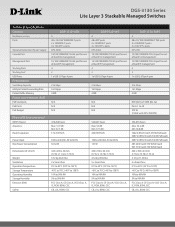
...Hours) Acoustics Heat Dissipation Power Input Max Power Consumption Dimensions (W xD x H) Weight Ventilation Operation Temperature Storage Temperature Operating Humidity Storage Humidity Emission (EMI) Safety DGS-3130-54TS A 48 x 10/100/1000BASE-T ports 2 x 10GBASE-T ports 4 x 10G SFP+ ports DPS-500A 10/100/1000BASE-T RJ-45 port for...-T RJ-45 port for outof-band CLI management 10/100/1000BASE-T RJ-45 port for outof-band IP management 4 2 1 x USB 2.0 Type A port DGS-3130-54PS A 48 x 10/100/1000BASE-T PoE ports 2 x 10GBASE-T ports 4 x 10G SFP+ ports DPS-700 10/100/1000BASE-T RJ-45 port for outof...
...Hours) Acoustics Heat Dissipation Power Input Max Power Consumption Dimensions (W xD x H) Weight Ventilation Operation Temperature Storage Temperature Operating Humidity Storage Humidity Emission (EMI) Safety DGS-3130-54TS A 48 x 10/100/1000BASE-T ports 2 x 10GBASE-T ports 4 x 10G SFP+ ports DPS-500A 10/100/1000BASE-T RJ-45 port for...-T RJ-45 port for outof-band CLI management 10/100/1000BASE-T RJ-45 port for outof-band IP management 4 2 1 x USB 2.0 Type A port DGS-3130-54PS A 48 x 10/100/1000BASE-T PoE ports 2 x 10GBASE-T ports 4 x 10G SFP+ ports DPS-700 10/100/1000BASE-T RJ-45 port for outof...
Datasheet
Page 7
... or registered trademarks are subject to change without notice, and actual product appearance may differ from Authorized US D-Link Reseller. When stacking the DGS-3130-54TS/54S/54PS models, the stacking cost is 6. HERRMANN STREET | FOUNTAIN VALLEY, CA 92708 | 800.326.1688 | DLINK.COM... ©2018 D-Link Corporation/D-Link Systems, Inc. Product specifications, size and shape are the property of 12 (2+2+8). 2 Lifetime Warranty...
... or registered trademarks are subject to change without notice, and actual product appearance may differ from Authorized US D-Link Reseller. When stacking the DGS-3130-54TS/54S/54PS models, the stacking cost is 6. HERRMANN STREET | FOUNTAIN VALLEY, CA 92708 | 800.326.1688 | DLINK.COM... ©2018 D-Link Corporation/D-Link Systems, Inc. Product specifications, size and shape are the property of 12 (2+2+8). 2 Lifetime Warranty...