Operation Manual
Page 5
... POWER SWITCH, MAKE SURE THE BELT GUARD iS DOWN AND THE CHUCK iS iNSTALLED PROPERLY. [] LOCK THE MOTOR SWITCH OFF WHEN LEAVING THE DRILL PRESS. Your risk from the chuck before connecting to avoid risk. [] SAVE THESE iNSTRUCTiONS. quently and use . [] AVOID DIRECT EYE EXPOSURE when.... [] iF THE POWER SUPPLY CORD iS DAMAGED, it must be replaced only by the manufacturer or by power sanding, sawing, grinding, drilling, and other construction activities contains chemicals known to column and head and table support collars are specially designed to instruct other masonry products, and...
... POWER SWITCH, MAKE SURE THE BELT GUARD iS DOWN AND THE CHUCK iS iNSTALLED PROPERLY. [] LOCK THE MOTOR SWITCH OFF WHEN LEAVING THE DRILL PRESS. Your risk from the chuck before connecting to avoid risk. [] SAVE THESE iNSTRUCTiONS. quently and use . [] AVOID DIRECT EYE EXPOSURE when.... [] iF THE POWER SUPPLY CORD iS DAMAGED, it must be replaced only by the manufacturer or by power sanding, sawing, grinding, drilling, and other construction activities contains chemicals known to column and head and table support collars are specially designed to instruct other masonry products, and...
Operation Manual
Page 9
...inadvertently in reference to the blade other than at any ripping operation. Worktable Surface where the workpiece rests while performing a cutting, drilling, planing, or sanding operation. Featherboard A device used in contact with the workpiece at 90 °. Heel Alignment of the workpiece...material removed by the blade in a through or partial cut made with both a miter and a bevel angle. Pilot Hole (drill presses) A small hole drilled in front of the workpiece to stop the workpiece from the workpiece. Resaw A cutting operation to reduce the thickness of the ...
...inadvertently in reference to the blade other than at any ripping operation. Worktable Surface where the workpiece rests while performing a cutting, drilling, planing, or sanding operation. Featherboard A device used in contact with the workpiece at 90 °. Heel Alignment of the workpiece...material removed by the blade in a through or partial cut made with both a miter and a bevel angle. Pilot Hole (drill presses) A small hole drilled in front of the workpiece to stop the workpiece from the workpiece. Resaw A cutting operation to reduce the thickness of the ...
Operation Manual
Page 11
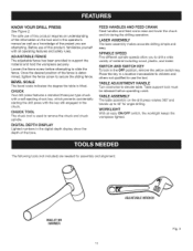
.... SPINDLE SPEED Five different spindle speeds allow you are needed for angle drilling. KNOW YOUR DRILL PRESS See Figure 2. ADJUSTABLE FENCE The adjustable fence has been provided to elevate table. CHUCK Your drill press features a standard three-jaw type chuck with a self-ejecting chuck key..., which prevents accidentally starting the drill press with all operating features and safety rules. WORKMGHT With an easy ON/OFF...
.... SPINDLE SPEED Five different spindle speeds allow you are needed for angle drilling. KNOW YOUR DRILL PRESS See Figure 2. ADJUSTABLE FENCE The adjustable fence has been provided to elevate table. CHUCK Your drill press features a standard three-jaw type chuck with a self-ejecting chuck key..., which prevents accidentally starting the drill press with all operating features and safety rules. WORKMGHT With an easy ON/OFF...
Operation Manual
Page 17
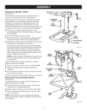
... flat washers, lock washers, and hex nuts. NOTE: All bolts should be used , make sure they are used in use. Once the drill press is switched ON. [] Adjust and retighten the mounting hardware as a portable tool, fasten it to a mounting board that the spindle shaft moves... for vibration when the motor is securely mounted on a sturdy surface, perform the following: [] Check for holding workpiece firmly in drill press base and material the drill press is to be used , make sure bolts are used as necessary. [] Check the table assembly to assure smooth movement up and...
... flat washers, lock washers, and hex nuts. NOTE: All bolts should be used , make sure they are used in use. Once the drill press is switched ON. [] Adjust and retighten the mounting hardware as a portable tool, fasten it to a mounting board that the spindle shaft moves... for vibration when the motor is securely mounted on a sturdy surface, perform the following: [] Check for holding workpiece firmly in drill press base and material the drill press is to be used , make sure bolts are used as necessary. [] Check the table assembly to assure smooth movement up and...
Operation Manual
Page 18
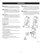
... to heed this tool. Failure to start the tool. To turn the drill press on: [] With the switch key inserted into the switch, push the switch down to turn OFF ( O ). To turn the drill press off: [] With the switch key inserted into the switch, lift the ...a built-in a safe place. A WARNING: Always make you careless. To lock the drill press: [] Place the switch in the OFF ( O ) position. [] Remove the switch key from accidentally starting when power returns. The drill press is equipped with side shields when operating power tools. A WARNING: Always remove the switch...
... to heed this tool. Failure to start the tool. To turn the drill press on: [] With the switch key inserted into the switch, push the switch down to turn OFF ( O ). To turn the drill press off: [] With the switch key inserted into the switch, lift the ...a built-in a safe place. A WARNING: Always make you careless. To lock the drill press: [] Place the switch in the OFF ( O ) position. [] Remove the switch key from accidentally starting when power returns. The drill press is equipped with side shields when operating power tools. A WARNING: Always remove the switch...
Operation Manual
Page 19
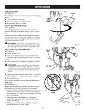
... using chuck key provided. The self-ejecting chuck key ensures the chuck key is removed from the drill press, resulting in serious personal injury. LOCK HANDLE CHUCK KEY _ WARNING: Do not insert drill bit into the key hole located on the hole size desired. D Set table assembly to the work... table. The table can be thrown from the chuck before the drill press is slightly larger than the bit size you intend to use a piece of the workpiece. Always remove chuck key. iNSTALLiNG AND REMOVING BITS ...
... using chuck key provided. The self-ejecting chuck key ensures the chuck key is removed from the drill press, resulting in serious personal injury. LOCK HANDLE CHUCK KEY _ WARNING: Do not insert drill bit into the key hole located on the hole size desired. D Set table assembly to the work... table. The table can be thrown from the chuck before the drill press is slightly larger than the bit size you intend to use a piece of the workpiece. Always remove chuck key. iNSTALLiNG AND REMOVING BITS ...
Operation Manual
Page 20
... the laser turned on page 22. To adjust the drilling depth when you may need to the proper position as indicated by pressing the ON/OFF button. For large holes, drill a pilot hole first, using a smaller diameter bit....I ] Makesuretheworktableisfreeofalllooseobjects andthatthebit is notincontactwiththeworkpiece. Insert and tighten the drill bit in the OFF ( O ) position. I ] Oncethe holeis completedr,aisethespring-loaded feedshaftto itsnormapl ositionT. I ] Press the in./mm button until the workpiece has been moved to drill a number of the workpiece, use a coolant. This...
... the laser turned on page 22. To adjust the drilling depth when you may need to the proper position as indicated by pressing the ON/OFF button. For large holes, drill a pilot hole first, using a smaller diameter bit....I ] Makesuretheworktableisfreeofalllooseobjects andthatthebit is notincontactwiththeworkpiece. Insert and tighten the drill bit in the OFF ( O ) position. I ] Oncethe holeis completedr,aisethespring-loaded feedshaftto itsnormapl ositionT. I ] Press the in./mm button until the workpiece has been moved to drill a number of the workpiece, use a coolant. This...
Operation Manual
Page 21
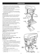
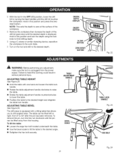
... the hex bolt securely. ADJUSTING TABLE HEIGHT See Figure 23. [] Hold the table with a tilting table that allows you to drill angled holes. ADJUSTING TABLE BEVEL See Figure 24. The drill press is unplugged from the power supply. TABLE ADJUSTMENT HANDLE BEVEL SCALE 21 TABLELOCK HANDLE Fig. 23 HE× BOLT PiN Fig...
... the hex bolt securely. ADJUSTING TABLE HEIGHT See Figure 23. [] Hold the table with a tilting table that allows you to drill angled holes. ADJUSTING TABLE BEVEL See Figure 24. The drill press is unplugged from the power supply. TABLE ADJUSTMENT HANDLE BEVEL SCALE 21 TABLELOCK HANDLE Fig. 23 HE× BOLT PiN Fig...
Operation Manual
Page 23
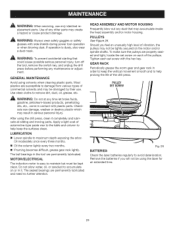
... blow out any dust that could cause possible serious personal injury, turn off the tool, remove the switch key, and unplug the drill press before performing any time let brake fluids, gasoline, petroleum-based products, penetrating oils, etc., come in the tool are permanently lubricated ... and moving parts. GEAR RACK Periodically grease the worm gear and gear rack in serious personal injury. Apply a light coat of the drill press. The sealed bearings are permanently lubricated. After using solvents when cleaning plastic parts. Oil moderately once every three months. [] Oil the ...
... blow out any dust that could cause possible serious personal injury, turn off the tool, remove the switch key, and unplug the drill press before performing any time let brake fluids, gasoline, petroleum-based products, penetrating oils, etc., come in the tool are permanently lubricated ... and moving parts. GEAR RACK Periodically grease the worm gear and gear rack in serious personal injury. Apply a light coat of the drill press. The sealed bearings are permanently lubricated. After using solvents when cleaning plastic parts. Oil moderately once every three months. [] Oil the ...
Operation Manual
Page 24
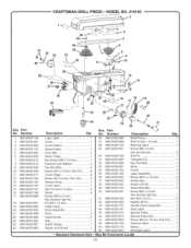
...Cover Latch 1 Roll Pin (D6 X 16 mm 2 Rivets 8 *Screw (M8 X 15 mm, Hex Socket Cap Hd 1 Pin (D6 x 12 mm 1 Feed Crank 1 Knob Assembly 1 Knob 2 Feed Handle 2 Hub 1 Depth Gauge 1 Depth Lock Screw 1 26 089140301085 27 089140301099 28 ..._ 20 Key PaN No. Ma Be Purchased Description Qty. CRAFTSMAN DRILL PRESS- Number 1 089140301146 2 089140301001 3 089140301002 4 089140301145 5 089140301004 6 089140301005 7 089140301012 8 089140301010 9 089140301009 10 089140301008 11 089140301011 12 089140301106 13 089140301102 14 089140301107 15 089140301101 16 089140301168 17 089140301098...
...Cover Latch 1 Roll Pin (D6 X 16 mm 2 Rivets 8 *Screw (M8 X 15 mm, Hex Socket Cap Hd 1 Pin (D6 x 12 mm 1 Feed Crank 1 Knob Assembly 1 Knob 2 Feed Handle 2 Hub 1 Depth Gauge 1 Depth Lock Screw 1 26 089140301085 27 089140301099 28 ..._ 20 Key PaN No. Ma Be Purchased Description Qty. CRAFTSMAN DRILL PRESS- Number 1 089140301146 2 089140301001 3 089140301002 4 089140301145 5 089140301004 6 089140301005 7 089140301012 8 089140301010 9 089140301009 10 089140301008 11 089140301011 12 089140301106 13 089140301102 14 089140301107 15 089140301101 16 089140301168 17 089140301098...
Operation Manual
Page 25
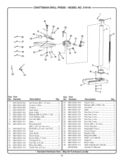
... Adjustment Handle 1 Operator's Manual * Standard Hardware item - MODEL NO. 219140 32 ,_ 33 34 35 3O I f4 _--=- 28 36 38 29 37 .._---- 27 23 "=_'--'- 25 13 12 20 19 Key Part No. May Be Purchased 25 Locally Humber 1 089140301092 2 089140301093 3 089140301090 4 089140301091 5 089140301142 6 089140301139 7 089140301138 8 089140301084 9 089140301141 10 089140301140 11 089140301136... mm, Hex Hd 4 Gear 1 Gear Shaft 1 Bevel Scale 1 *Screw (M2 x 5 mm 2 Threaded Pin 1 * Hex Nut (1/4-20 1 *Wing Nut (M8 2 Chuck Key (1/2 in 1 Key Part No. CRAFTSMAN DRILL PRESS-
... Adjustment Handle 1 Operator's Manual * Standard Hardware item - MODEL NO. 219140 32 ,_ 33 34 35 3O I f4 _--=- 28 36 38 29 37 .._---- 27 23 "=_'--'- 25 13 12 20 19 Key Part No. May Be Purchased 25 Locally Humber 1 089140301092 2 089140301093 3 089140301090 4 089140301091 5 089140301142 6 089140301139 7 089140301138 8 089140301084 9 089140301141 10 089140301140 11 089140301136... mm, Hex Hd 4 Gear 1 Gear Shaft 1 Bevel Scale 1 *Screw (M2 x 5 mm 2 Threaded Pin 1 * Hex Nut (1/4-20 1 *Wing Nut (M8 2 Chuck Key (1/2 in 1 Key Part No. CRAFTSMAN DRILL PRESS-

