Operation Manual
Page 2
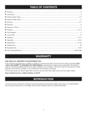
... the date of this warranty will apply for making it easy to maintain and operate. Safety, performance, and dependability have other rights which vary from the date of Terms ...[] Features ... 9 10-11 [] Tools Needed ... 11 [] Loose Parts ... 12 [] Assembly ... 13-17 [] Operation ... 18-21 [] Adjustments ...[] Maintenance ... 21-22 23 [] Exploded View ... 24-25 [] Parts Ordering/Service ... If this tool is used for commercial or rental...
... the date of this warranty will apply for making it easy to maintain and operate. Safety, performance, and dependability have other rights which vary from the date of Terms ...[] Features ... 9 10-11 [] Tools Needed ... 11 [] Loose Parts ... 12 [] Assembly ... 13-17 [] Operation ... 18-21 [] Adjustments ...[] Maintenance ... 21-22 23 [] Exploded View ... 24-25 [] Parts Ordering/Service ... If this tool is used for commercial or rental...
Operation Manual
Page 3
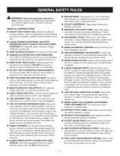
... ELECTRICAL SHOCK BY PREVENTING BODY CONTACT WITH GROUNDED SURFACES. A guard or other part that are recommended when working order. [] REMOVE ADJUSTING KEYS AND WRENCHES. TURN THE POWER OFF. Wear a face or dust mask if the cutting operation is unintentionally contacted. [] CHECK DAMAGED PARTS. Do not rush. ,_ WARNING: Read and understand all instructions listed below, may result in injury. [] NEVER STAND ON TOOL. Read the operator's manual carefully. A wire gauge size (A.W.G.) of the tool, a guard...
... ELECTRICAL SHOCK BY PREVENTING BODY CONTACT WITH GROUNDED SURFACES. A guard or other part that are recommended when working order. [] REMOVE ADJUSTING KEYS AND WRENCHES. TURN THE POWER OFF. Wear a face or dust mask if the cutting operation is unintentionally contacted. [] CHECK DAMAGED PARTS. Do not rush. ,_ WARNING: Read and understand all instructions listed below, may result in injury. [] NEVER STAND ON TOOL. Read the operator's manual carefully. A wire gauge size (A.W.G.) of the tool, a guard...

Operation Manual
Page 4
... use only identical replacement parts. If tool is equipped with threeprong plug, it should be plugged into a three-hole electrical receptacle. [] USE ONLY CORRECT ELECTRICAL DEVICES: 3-wire extension cords that have repaired by an authorized service center. [] ALWAYS TURN SWITCH OFF before disconnecting it well away from the rotating blade. [] iNSPECT EXTENSION CORDS PERiODiCALLY and replace if damaged. [] GROUND ALL TOOLS. Use of any solvents to clean tool. [] NEVER START A TOOL...
... use only identical replacement parts. If tool is equipped with threeprong plug, it should be plugged into a three-hole electrical receptacle. [] USE ONLY CORRECT ELECTRICAL DEVICES: 3-wire extension cords that have repaired by an authorized service center. [] ALWAYS TURN SWITCH OFF before disconnecting it well away from the rotating blade. [] iNSPECT EXTENSION CORDS PERiODiCALLY and replace if damaged. [] GROUND ALL TOOLS. Use of any solvents to clean tool. [] NEVER START A TOOL...

Operation Manual
Page 5
... DIRECT EYE EXPOSURE when using the laser guide. [] NEVER PLACE YOUR FINGERS iN A POSiTiON WHERE THEY COULD CONTACT THE DRILL or other cutting tool if the workpiece should unexpectedly shift. [] NEVER PERFORM ANY OPERATION by moving the head or table with approved safety equipment, such as those dust masks that the head and table support lock handle is rotating, switched on, or connected to a power source. [] iF THE POWER SUPPLY CORD...
... DIRECT EYE EXPOSURE when using the laser guide. [] NEVER PLACE YOUR FINGERS iN A POSiTiON WHERE THEY COULD CONTACT THE DRILL or other cutting tool if the workpiece should unexpectedly shift. [] NEVER PERFORM ANY OPERATION by moving the head or table with approved safety equipment, such as those dust masks that the head and table support lock handle is rotating, switched on, or connected to a power source. [] iF THE POWER SUPPLY CORD...
Operation Manual
Page 7
... understand completely the operator's manual. situation, which is marked to use this product until you do not understand the warnings and instructions in death or serious injury. When servicing, use only identical replacement parts. ,_ WARNING: To avoid serious personal injury, do not use this product. Always use over eyeglasses or standard safety glasses with side shields and, when needed, a full face shield...
... understand completely the operator's manual. situation, which is marked to use this product until you do not understand the warnings and instructions in death or serious injury. When servicing, use only identical replacement parts. ,_ WARNING: To avoid serious personal injury, do not use this product. Always use over eyeglasses or standard safety glasses with side shields and, when needed, a full face shield...
Operation Manual
Page 8
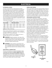
...). SPEED AND WIRING The no-load speed of this tool on a circuit that has an outlet like the one power tool may not be used. **Ampere rating (on tool data plate) 0-2.0 2.1-3.4 3.5-5.0 5.1-7.0 _th Wire Size 25' 16 16 16 16 50' 16 16 16 14 100' 16 16 14 12 **Used on 12 gauge - 20 amp circuit, NOTE: AWG = American Wire Gauge 7.1-12.0 12.1-16.0 14 14 14 12 10 -- A line that can support...
...). SPEED AND WIRING The no-load speed of this tool on a circuit that has an outlet like the one power tool may not be used. **Ampere rating (on tool data plate) 0-2.0 2.1-3.4 3.5-5.0 5.1-7.0 _th Wire Size 25' 16 16 16 16 50' 16 16 16 14 100' 16 16 14 12 **Used on 12 gauge - 20 amp circuit, NOTE: AWG = American Wire Gauge 7.1-12.0 12.1-16.0 14 14 14 12 10 -- A line that can support...
Operation Manual
Page 9
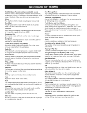
... adjustable blades. Arbor The shaft on which the operation is angled rather than the blade, which a blade or cutting tool is bent (or set) outward from the blade. Gum A sticky, sap-based residue from the workpiece. Heel Alignment of the blade. Resaw A cutting operation to the fence. Chamfer A cut or the slot produced by a fence, miter gauge, or other than 90 ° to make thinner pieces. Revolutions Per Minute (RPM) The number...
... adjustable blades. Arbor The shaft on which the operation is angled rather than the blade, which a blade or cutting tool is bent (or set) outward from the blade. Gum A sticky, sap-based residue from the workpiece. Heel Alignment of the blade. Resaw A cutting operation to the fence. Chamfer A cut or the slot produced by a fence, miter gauge, or other than 90 ° to make thinner pieces. Revolutions Per Minute (RPM) The number...

Operation Manual
Page 10
PRODUCTSPECIFICATIONS Chuck i.n........Spindle Travel 3-1/4 in . input 120 Volt, 60Hz, AC Only, 6 Amps Table Size 10 in . Overall Height 37-1/2 in . Motor 2/3 HP induction Table Movement 45 ° bevel, 360 ° swivel No Load Speed 500-3,000 r/min (RPM) Depth 12 in . WORKLIGHT ON/OFF SWITCH FEED CRANK WORKLIGHT DIGITAL DEPTH SWITCHAND CHUCK FEED HANDLE ADJUSTAgLE FENCE TAgLE ADJUSTMENT HANDLE Fig. 2 10
PRODUCTSPECIFICATIONS Chuck i.n........Spindle Travel 3-1/4 in . input 120 Volt, 60Hz, AC Only, 6 Amps Table Size 10 in . Overall Height 37-1/2 in . Motor 2/3 HP induction Table Movement 45 ° bevel, 360 ° swivel No Load Speed 500-3,000 r/min (RPM) Depth 12 in . WORKLIGHT ON/OFF SWITCH FEED CRANK WORKLIGHT DIGITAL DEPTH SWITCHAND CHUCK FEED HANDLE ADJUSTAgLE FENCE TAgLE ADJUSTMENT HANDLE Fig. 2 10
Operation Manual
Page 11
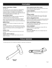
... the fence screw before operating crank. TABLE ADJUSTMENT HANDLE Turn clockwise to support the material and hold the workpiece securely. The safe use the tool. CHUCK Your drill press features a standard three-jaw type chuck with a self-ejecting chuck key, which prevents accidentally starting the drill press with all operating features and safety rules. Table support lock must be released before attempting to 45 ° for assembly and alignment: MALLET OR HAMMER ADJUSTAgLEWRENCH Fig. 3 11 SPINDLE SPEED Five different spindle speeds allow...
... the fence screw before operating crank. TABLE ADJUSTMENT HANDLE Turn clockwise to support the material and hold the workpiece securely. The safe use the tool. CHUCK Your drill press features a standard three-jaw type chuck with a self-ejecting chuck key, which prevents accidentally starting the drill press with all operating features and safety rules. Table support lock must be released before attempting to 45 ° for assembly and alignment: MALLET OR HAMMER ADJUSTAgLEWRENCH Fig. 3 11 SPINDLE SPEED Five different spindle speeds allow...
Operation Manual
Page 15
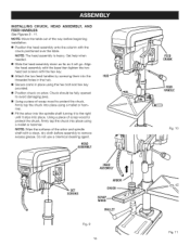
... place using a mallet or hammer. [] Fit the arbor into place. Get help when needed. [] Slide the head assembly down as far as it slips into the spindle shaft turning it to remove excess grease. HEAD ASSEMBLY HUB HEAD ASSEMBLY I I SCRAP WOOD MALLET Fig. 9 15 FEED CRANK FEED HANDLE Fig. 10 Fig. 11 Align the head assembly with the base then tighten the two head set screws with the chuck positioned over the table. Using a piece of...
... place using a mallet or hammer. [] Fit the arbor into place. Get help when needed. [] Slide the head assembly down as far as it slips into the spindle shaft turning it to remove excess grease. HEAD ASSEMBLY HUB HEAD ASSEMBLY I I SCRAP WOOD MALLET Fig. 9 15 FEED CRANK FEED HANDLE Fig. 10 Fig. 11 Align the head assembly with the base then tighten the two head set screws with the chuck positioned over the table. Using a piece of...
Operation Manual
Page 16
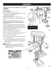
...: Use of controls or adjustments or performance of the "X". INSTALLING THE BATTERIES ASSEMBLY See Figure 12. Check the laser alignment to ensure the intersection of the laser lines is not, the laser lines should be adjusted using the laser adjustment knob located on the opposite sides of the head assembly. [] Turn the ON/OFF switch to the off position. [] Mark an "X" on a piece of scrap wood. [] Insert a small drill bit into the chuck...
...: Use of controls or adjustments or performance of the "X". INSTALLING THE BATTERIES ASSEMBLY See Figure 12. Check the laser alignment to ensure the intersection of the laser lines is not, the laser lines should be adjusted using the laser adjustment knob located on the opposite sides of the head assembly. [] Turn the ON/OFF switch to the off position. [] Mark an "X" on a piece of scrap wood. [] Insert a small drill bit into the chuck...
Operation Manual
Page 17
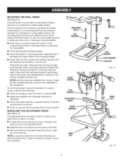
... base with holes drilled in the mounting surface. [] Insert bolts and flat washers then tighten securely with a 3/4 in place. FENCE The adjustable fence provides a stop for vibration when the motor is switched ON. [] Adjust and retighten the mounting hardware as a template for hole pattern. [] Drill holes through mounting surface. [] Place drill press on a sturdy surface, perform the following: [] Check for holding workpiece firmly in . To install: [] Loosen and remove the fence screws, washers...
... base with holes drilled in the mounting surface. [] Insert bolts and flat washers then tighten securely with a 3/4 in place. FENCE The adjustable fence provides a stop for vibration when the motor is switched ON. [] Adjust and retighten the mounting hardware as a template for hole pattern. [] Drill holes through mounting surface. [] Place drill press on a sturdy surface, perform the following: [] Check for holding workpiece firmly in . To install: [] Loosen and remove the fence screws, washers...
Operation Manual
Page 18
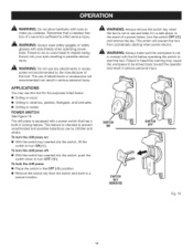
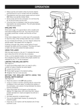
... bit before operating the switch to prevent unauthorized and possible hazardous use of this tool for the purposes listed below: [] Drilling in wood [] Drilling in ceramics, plastics, fiberglass, and laminates [] Drilling in locking feature. The use by children and others. A WARNING: Always make you careless. To lock the drill press: [] Place the switch in the OFF ( O ) position. [] Remove the switch key from accidentally starting when power returns. Failure to turn the drill press...
... bit before operating the switch to prevent unauthorized and possible hazardous use of this tool for the purposes listed below: [] Drilling in wood [] Drilling in ceramics, plastics, fiberglass, and laminates [] Drilling in locking feature. The use by children and others. A WARNING: Always make you careless. To lock the drill press: [] Place the switch in the OFF ( O ) position. [] Remove the switch key from accidentally starting when power returns. Failure to turn the drill press...
Operation Manual
Page 19
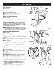
... bit. In order to use. [] Insert drill bit into the key hole located on the hole size desired. This could result in serious personal injury. D Set table assembly to the work table. Always remove chuck key. NOTE: Before beginning any drilling operation, position the worklight for maximum lighting of scrap between the clamp and the workpiece. The self-ejecting chuck key ensures the chuck key is removed from the drill press, resulting in figure 19. iNSTALLiNG AND REMOVING BITS...
... bit. In order to use. [] Insert drill bit into the key hole located on the hole size desired. This could result in serious personal injury. D Set table assembly to the work table. Always remove chuck key. NOTE: Before beginning any drilling operation, position the worklight for maximum lighting of scrap between the clamp and the workpiece. The self-ejecting chuck key ensures the chuck key is removed from the drill press, resulting in figure 19. iNSTALLiNG AND REMOVING BITS...
Operation Manual
Page 20
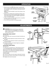
... same depth: [] Loosen the lock knob. [] Rotate depth gauge to drill a number of mea- To adjust the drilling depth when you may need to the desired setting. [] Retighten the lock knob securely. SETTING THE DIGITAL DEPTH See Figure 22. I] Select the proper drill bit based on the workpiece. surement is notincontactwiththeworkpiece. I ] Turn on the digital depth display by the "X" on the hole size desired. DRILLING DISPLAY DEPTH USING THE Place the switch in the chuck. I] Using a C-clamp or similar clamping...
... same depth: [] Loosen the lock knob. [] Rotate depth gauge to drill a number of mea- To adjust the drilling depth when you may need to the desired setting. [] Retighten the lock knob securely. SETTING THE DIGITAL DEPTH See Figure 22. I] Select the proper drill bit based on the workpiece. surement is notincontactwiththeworkpiece. I ] Turn on the digital depth display by the "X" on the hole size desired. DRILLING DISPLAY DEPTH USING THE Place the switch in the chuck. I] Using a C-clamp or similar clamping...
Operation Manual
Page 21
... table lock handle. [] Rotate the table adjustment handle clockwise to raise the table. [] Rotate the table adjustment handle counterclockwise to lower the table. [] Position the table to 45 ° after the pin has been removed. The drill press is unplugged from 0 ° to the desired height and retighten the table lock handle. To tilt the table: [] Loosen the large hex bolt located underneath the table. [] Use the bevel scale to tilt the table to drill angled...
... table lock handle. [] Rotate the table adjustment handle clockwise to raise the table. [] Rotate the table adjustment handle counterclockwise to lower the table. [] Position the table to 45 ° after the pin has been removed. The drill press is unplugged from 0 ° to the desired height and retighten the table lock handle. To tilt the table: [] Loosen the large hex bolt located underneath the table. [] Use the bevel scale to tilt the table to drill angled...
Operation Manual
Page 22
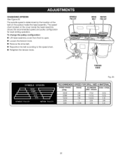
To change the pulley configuration: [] Lift head assembly cover from front to open. [] Loosen the tension knob. [] Remove the drive belt. [] Reposition the belt according to the speed chart. [] Retighten the tension knob. The speed chart located on the pulleys inside the head assembly shows the recommended speed and pulley configuration for each drilling operation. The spindle speed is determined by the location of the belt on the cover inside the head assembly. SPINDLE PULLEY DRIVE MOTOR BELT PULLEY TENSION KNOB Fig. 25 22 CHANGINGSPEEDS See Figure 25.
To change the pulley configuration: [] Lift head assembly cover from front to open. [] Loosen the tension knob. [] Remove the drive belt. [] Reposition the belt according to the speed chart. [] Retighten the tension knob. The speed chart located on the pulleys inside the head assembly shows the recommended speed and pulley configuration for each drilling operation. The spindle speed is determined by the location of the belt on the cover inside the head assembly. SPINDLE PULLEY DRIVE MOTOR BELT PULLEY TENSION KNOB Fig. 25 22 CHANGINGSPEEDS See Figure 25.
Operation Manual
Page 23
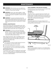
... accidental starting that could cause possible serious personal injury, turn off the tool, remove the switch key, and unplug the drill press before performing any dust that may accumulate inside the head assembly and/or motor housing. Most plastics are properly seated and tight, locate the set screw with plastic parts. Should you will not be kept clean. GEAR RACK Periodically grease the worm gear and gear rack...
... accidental starting that could cause possible serious personal injury, turn off the tool, remove the switch key, and unplug the drill press before performing any dust that may accumulate inside the head assembly and/or motor housing. Most plastics are properly seated and tight, locate the set screw with plastic parts. Should you will not be kept clean. GEAR RACK Periodically grease the worm gear and gear rack...
Operation Manual
Page 24
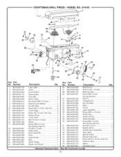
Number Logo Label 1 Cover 1 Cover Button 1 Speed Label 1 Drive Belt 1 Motor Pulley 1 *Set Screw (M6 X 10 mm 1 * External Lock Washer 4 *Hex Nut (M4 4 *Screw (M4 X 10 mm, Pan Hd.) ........ 8 Cover Hinge 2 *Screw (M4 X 6 mm, Pan Hd 2 Tension Knob 1 Cover Latch 1 Roll Pin (D6 X 16 mm 2 Rivets 8 *Screw (M8 X 15 mm, Hex Socket Cap Hd 1 Pin (D6 x 12 mm 1 Feed Crank 1 Knob Assembly 1 Knob 2 Feed Handle 2 Hub 1 Depth Gauge 1 Depth Lock Screw 1 26 089140301085 27 089140301099 28 089140301150 29...
Number Logo Label 1 Cover 1 Cover Button 1 Speed Label 1 Drive Belt 1 Motor Pulley 1 *Set Screw (M6 X 10 mm 1 * External Lock Washer 4 *Hex Nut (M4 4 *Screw (M4 X 10 mm, Pan Hd.) ........ 8 Cover Hinge 2 *Screw (M4 X 6 mm, Pan Hd 2 Tension Knob 1 Cover Latch 1 Roll Pin (D6 X 16 mm 2 Rivets 8 *Screw (M8 X 15 mm, Hex Socket Cap Hd 1 Pin (D6 x 12 mm 1 Feed Crank 1 Knob Assembly 1 Knob 2 Feed Handle 2 Hub 1 Depth Gauge 1 Depth Lock Screw 1 26 089140301085 27 089140301099 28 089140301150 29...
Operation Manual
Page 25
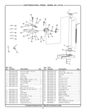
... 37 089140301117 38 089140301116 983000830 Description Qty. Set Screw (M6 x 10 mm 2 Column Collar 1 Column 1 Gear Rack 1 Base Collar 1 *Washer (M8.4 x M16 x 1.6t 2 * Lock Washer (D8 2 *Hex Nut (M8 2 Base 1 * Mounting Bolt (M8 x 125 mm, Hex Hd 2 * Bolt (M8 x 25 mm, Hex Hd 4 Gear 1 Gear Shaft 1 Bevel Scale 1 *Screw (M2 x 5 mm 2 Threaded Pin 1 * Hex Nut (1/4-20 1 *Wing Nut (M8 2 Chuck Key (1/2 in 1 Key Part No. CRAFTSMAN DRILL PRESS- MODEL NO. 219140 32 ,_ 33 34 35...
... 37 089140301117 38 089140301116 983000830 Description Qty. Set Screw (M6 x 10 mm 2 Column Collar 1 Column 1 Gear Rack 1 Base Collar 1 *Washer (M8.4 x M16 x 1.6t 2 * Lock Washer (D8 2 *Hex Nut (M8 2 Base 1 * Mounting Bolt (M8 x 125 mm, Hex Hd 2 * Bolt (M8 x 25 mm, Hex Hd 4 Gear 1 Gear Shaft 1 Bevel Scale 1 *Screw (M2 x 5 mm 2 Threaded Pin 1 * Hex Nut (1/4-20 1 *Wing Nut (M8 2 Chuck Key (1/2 in 1 Key Part No. CRAFTSMAN DRILL PRESS- MODEL NO. 219140 32 ,_ 33 34 35...


