Operation Manual
Page 5
... To reduce your exposure to these chemicals are specially designed to power source or turning power ON. [] ADJUST THE TABLE OR DEPTH STOP TO AVOID DRiLLiNG iNTO THE TABLE. Do not perform layout, assembly, or set-up work on the table while the cutting tool is clamped tight to column and... BELT GUARD iS DOWN AND THE CHUCK iS iNSTALLED PROPERLY. [] LOCK THE MOTOR SWITCH OFF WHEN LEAVING THE DRILL PRESS. If you do this tool, loan them fre- Shut off the power, remove the drill bit, and clean the table before checking that the head and table support lock handle is rotating, switched...
... To reduce your exposure to these chemicals are specially designed to power source or turning power ON. [] ADJUST THE TABLE OR DEPTH STOP TO AVOID DRiLLiNG iNTO THE TABLE. Do not perform layout, assembly, or set-up work on the table while the cutting tool is clamped tight to column and... BELT GUARD iS DOWN AND THE CHUCK iS iNSTALLED PROPERLY. [] LOCK THE MOTOR SWITCH OFF WHEN LEAVING THE DRILL PRESS. If you do this tool, loan them fre- Shut off the power, remove the drill bit, and clean the table before checking that the head and table support lock handle is rotating, switched...
Operation Manual
Page 9
...Non-Through Cuts Any cutting operation where the blade does not extend completely through the thickness of adjustable blades. Pilot Hole (drill presses) A small hole drilled in a workpiece that has hardened. As it securely against the table or fence during a ripping operation. Compound Cut ...blades when the workpiece is not properly supported. Push Blocks and Push Sticks Devices used for drilling large holes accurately. Worktable Surface where the workpiece rests while performing a cutting, drilling, planing, or sanding operation. Bevel Cut A cutting operation made at 90 °. ...
...Non-Through Cuts Any cutting operation where the blade does not extend completely through the thickness of adjustable blades. Pilot Hole (drill presses) A small hole drilled in a workpiece that has hardened. As it securely against the table or fence during a ripping operation. Compound Cut ...blades when the workpiece is not properly supported. Push Blocks and Push Sticks Devices used for drilling large holes accurately. Worktable Surface where the workpiece rests while performing a cutting, drilling, planing, or sanding operation. Bevel Cut A cutting operation made at 90 °. ...
Operation Manual
Page 11
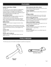
...knowledge of the fence is determined, tighten the fence screw to use of this product requires an understanding of the information on the drill press rotates 360 ° and bevels up to slide the fence. SWITCH AND SWITCH KEY To lock in a location inaccessible to ... spindle. The following tools (not included) are attempting. KNOW YOUR DRILL PRESS See Figure 2. CHUCK Your drill press features a standard three-jaw type chuck with a self-ejecting chuck key, which prevents accidentally starting the drill press with all operating features and safety rules. Place the key in the...
...knowledge of the fence is determined, tighten the fence screw to use of this product requires an understanding of the information on the drill press rotates 360 ° and bevels up to slide the fence. SWITCH AND SWITCH KEY To lock in a location inaccessible to ... spindle. The following tools (not included) are attempting. KNOW YOUR DRILL PRESS See Figure 2. CHUCK Your drill press features a standard three-jaw type chuck with a self-ejecting chuck key, which prevents accidentally starting the drill press with all operating features and safety rules. Place the key in the...
Operation Manual
Page 17
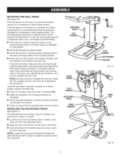
... when the motor is to be used , make sure they are long enough to go through holes in drill press, the material being mounted to a workbench or other stable surface. If the drill press is switched ON. [] Adjust and retighten the mounting hardware as needed to a mounting board that the spindle...Fig. 14 WiNG NUT Fig. 15 NOTE: All bolts should be inserted from the underside of sufficient size to avoid tipping while drill press is in drill press base and material the drill press is to be used , make sure bolts are long enough to , and the lock washers and hex nuts. If the...
... when the motor is to be used , make sure they are long enough to go through holes in drill press, the material being mounted to a workbench or other stable surface. If the drill press is switched ON. [] Adjust and retighten the mounting hardware as needed to a mounting board that the spindle...Fig. 14 WiNG NUT Fig. 15 NOTE: All bolts should be inserted from the underside of sufficient size to avoid tipping while drill press is in drill press base and material the drill press is to be used , make sure bolts are long enough to , and the lock washers and hex nuts. If the...
Operation Manual
Page 18
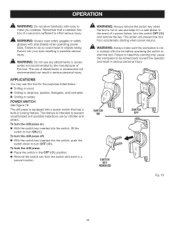
...switch that a careless fraction of this tool. This action will prevent the tool from the switch and store in a secure location. To turn the drill press off: [] With the switch key inserted into your eyes resulting in possible serious injury. _, WARNING: Do not use by the manufacturer of a ...lift the switch to do so could result in objects being thrown into the switch, push the switch down to turn ON ( I ). To lock the drill press: [] Place the switch in the OFF ( O ) position. [] Remove the switch key from accidentally starting when power returns. A WARNING: Always remove the...
...switch that a careless fraction of this tool. This action will prevent the tool from the switch and store in a secure location. To turn the drill press off: [] With the switch key inserted into your eyes resulting in possible serious injury. _, WARNING: Do not use by the manufacturer of a ...lift the switch to do so could result in objects being thrown into the switch, push the switch down to turn ON ( I ). To lock the drill press: [] Place the switch in the OFF ( O ) position. [] Remove the switch key from accidentally starting when power returns. A WARNING: Always remove the...
Operation Manual
Page 19
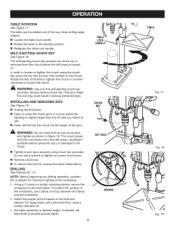
...Figure 18. Rotate the key clockwise to tighten the chuck or counterclockwise to the work table. iNSTALLiNG AND REMOVING BITS See Figure 19. [] Unplug the drill press. [] Open or close the chuck jaws to a point where the opening is turned On. This could result in serious personal injury. Do not use... spindle depth. 19 KEYHOLE WRONG TABLE Fig. 17 Fig. 18 Fig. 19 The self-ejecting chuck key ensures the chuck key is removed from the drill press, resulting in figure 19. In order to the chuck. [] Tighten chuck jaws securely using a smaller diameter bit. LOCK HANDLE CHUCK KEY _ WARNING: ...
...Figure 18. Rotate the key clockwise to tighten the chuck or counterclockwise to the work table. iNSTALLiNG AND REMOVING BITS See Figure 19. [] Unplug the drill press. [] Open or close the chuck jaws to a point where the opening is turned On. This could result in serious personal injury. Do not use... spindle depth. 19 KEYHOLE WRONG TABLE Fig. 17 Fig. 18 Fig. 19 The self-ejecting chuck key ensures the chuck key is removed from the drill press, resulting in figure 19. In order to the chuck. [] Tighten chuck jaws securely using a smaller diameter bit. LOCK HANDLE CHUCK KEY _ WARNING: ...
Operation Manual
Page 20
...C-clamp or similar clamping device, secure the workpiece to the proper position as indicated by pressing the ON/OFF button. Insert and tighten the drill bit in the OFF ( O ) position. I ] Select the proper drill bit based on the digital depth display by the "X" on the workpiece. I ] ... the hole size desired. I ] Slowlylowerdrillbit intoworkpieceD. If the hole is notincontactwiththeworkpiece. This step will enter the workpiece. LIMITING THE DRILLING DEPTH See Figure 21. I ] Press the in./mm button until the workpiece has been moved to the work table. As you increase the...
...C-clamp or similar clamping device, secure the workpiece to the proper position as indicated by pressing the ON/OFF button. Insert and tighten the drill bit in the OFF ( O ) position. I ] Select the proper drill bit based on the digital depth display by the "X" on the workpiece. I ] ... the hole size desired. I ] Slowlylowerdrillbit intoworkpieceD. If the hole is notincontactwiththeworkpiece. This step will enter the workpiece. LIMITING THE DRILLING DEPTH See Figure 21. I ] Press the in./mm button until the workpiece has been moved to the work table. As you increase the...
Operation Manual
Page 21
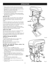
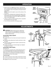
...inthe OFF( O) position,lowerthedrill bit byturningthefeedhandlesuntilthedrillbittouches the workpieceH. DIGITAL DEPTH ON/OFF BUTTON in serious personal injury. ADJUSTING TABLE BEVEL See Figure 24. The drill press is unplugged from the housing. The table can be tilted left or right, from 0 ° to the desired height and retighten the table lock ...Usinga C-clampor similarclampingdevice,reposition the workpieceto theworktable. D Turnonthetoolanddrilltothedesireddepth. ADJUSTING TABLE HEIGHT See Figure 23. [] Hold the table with a tilting table that allows you to drill angled holes.
...inthe OFF( O) position,lowerthedrill bit byturningthefeedhandlesuntilthedrillbittouches the workpieceH. DIGITAL DEPTH ON/OFF BUTTON in serious personal injury. ADJUSTING TABLE BEVEL See Figure 24. The drill press is unplugged from the housing. The table can be tilted left or right, from 0 ° to the desired height and retighten the table lock ...Usinga C-clampor similarclampingdevice,reposition the workpieceto theworktable. D Turnonthetoolanddrilltothedesireddepth. ADJUSTING TABLE HEIGHT See Figure 23. [] Hold the table with a tilting table that allows you to drill angled holes.
Operation Manual
Page 23
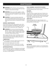
...HOUSING Frequently blow out any dust that could cause possible serious personal injury, turn off the tool, remove the switch key, and unplug the drill press before performing any time let brake fluids, gasoline, petroleum-based products, penetrating oils, etc., come in contact with the hex key. Should you... locate the set screw on each set screw with plastic parts. Use clean cloths to maintain but must be using the drill press, clean it . Tighten each of the drill press. After using the laser for an extended time. 23 Apply a light coat of automotive-type paste wax to the table...
...HOUSING Frequently blow out any dust that could cause possible serious personal injury, turn off the tool, remove the switch key, and unplug the drill press before performing any time let brake fluids, gasoline, petroleum-based products, penetrating oils, etc., come in contact with the hex key. Should you... locate the set screw on each set screw with plastic parts. Use clean cloths to maintain but must be using the drill press, clean it . Tighten each of the drill press. After using the laser for an extended time. 23 Apply a light coat of automotive-type paste wax to the table...
Operation Manual
Page 24
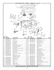
CRAFTSMAN DRILL PRESS- Number Logo Label 1 Cover 1 Cover Button 1 Speed Label 1 Drive Belt 1 Motor Pulley 1 *Set Screw (M6 X 10 mm 1 * External Lock Washer 4 *Hex Nut (M4... NO. 219140 _ 20 Key PaN No. Number 1 089140301146 2 089140301001 3 089140301002 4 089140301145 5 089140301004 6 089140301005 7 089140301012 8 089140301010 9 089140301009 10 089140301008 11 089140301011 12 089140301106 13 089140301102 14 089140301107 15 089140301101 16 089140301168 17 089140301098 18 089140301097 19 089140301096 20 089140301095 21 089140301089 22 089140301088 23 089140301094 24 089140301087...
CRAFTSMAN DRILL PRESS- Number Logo Label 1 Cover 1 Cover Button 1 Speed Label 1 Drive Belt 1 Motor Pulley 1 *Set Screw (M6 X 10 mm 1 * External Lock Washer 4 *Hex Nut (M4... NO. 219140 _ 20 Key PaN No. Number 1 089140301146 2 089140301001 3 089140301002 4 089140301145 5 089140301004 6 089140301005 7 089140301012 8 089140301010 9 089140301009 10 089140301008 11 089140301011 12 089140301106 13 089140301102 14 089140301107 15 089140301101 16 089140301168 17 089140301098 18 089140301097 19 089140301096 20 089140301095 21 089140301089 22 089140301088 23 089140301094 24 089140301087...
Operation Manual
Page 25
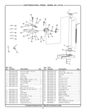
... 1 Operator's Manual * Standard Hardware item - Humber 1 089140301092 2 089140301093 3 089140301090 4 089140301091 5 089140301142 6 089140301139 7 089140301138 8 089140301084 9 089140301141 10 089140301140 11 089140301136 12 089140301135 13 089140301134 14 089140301133 15 089140301132 16 089140301131 17 089140301130 18 089140301128 19 089140301153 Description Qty. Humber 20 089140301154 21 089140301120 22 089140301129 23... Part No. MODEL NO. 219140 32 ,_ 33 34 35 3O I f4 _--=- 28 36 38 29 37 .._---- 27 23 "=_'--'- 25 13 12 20 19 Key Part No. CRAFTSMAN DRILL PRESS-
... 1 Operator's Manual * Standard Hardware item - Humber 1 089140301092 2 089140301093 3 089140301090 4 089140301091 5 089140301142 6 089140301139 7 089140301138 8 089140301084 9 089140301141 10 089140301140 11 089140301136 12 089140301135 13 089140301134 14 089140301133 15 089140301132 16 089140301131 17 089140301130 18 089140301128 19 089140301153 Description Qty. Humber 20 089140301154 21 089140301120 22 089140301129 23... Part No. MODEL NO. 219140 32 ,_ 33 34 35 3O I f4 _--=- 28 36 38 29 37 .._---- 27 23 "=_'--'- 25 13 12 20 19 Key Part No. CRAFTSMAN DRILL PRESS-

