
Setup Manual
Page 2
Table of Contents Chapter 1: Introduction 3 1.1 Before You Start 3 1.2 Package Checklist 3 1.3 Motherboard Features 4 1.4 Rear Panel Connectors 5 1.5 Motherboard Layout 6 Chapter 2: Hardware Installation 7 2.1 Installing Central Processing Unit (CPU 7 2.2 Fan Headers 9 2.3 Installing System Memory 10 2.4 Connectors and Slots 11 Chapter 3: Headers & Jumpers Setup 13 3.1 How to Setup Jumpers 13 3.2 Detail Settings 13 Chapter 4: RAID ...
Table of Contents Chapter 1: Introduction 3 1.1 Before You Start 3 1.2 Package Checklist 3 1.3 Motherboard Features 4 1.4 Rear Panel Connectors 5 1.5 Motherboard Layout 6 Chapter 2: Hardware Installation 7 2.1 Installing Central Processing Unit (CPU 7 2.2 Fan Headers 9 2.3 Installing System Memory 10 2.4 Connectors and Slots 11 Chapter 3: Headers & Jumpers Setup 13 3.1 How to Setup Jumpers 13 3.2 Detail Settings 13 Chapter 4: RAID ...

Setup Manual
Page 4
... 10 / 100 Mb/s auto negotiation Half / Full duplex capability Integrated Serial ATA Controller Data transfer rates up to 1.5 Gb/s. Motherboard Manual 1.3 MOTHERBOARD FEATURES CPU FSB P4M900-M7 SE P4M890-M7 TE LGA 775 LGA 775 Intel Core2Duo/ Pentium 4 / Pentium D / Intel Core2Duo/ Pentium 4 / Pentium D / Celeron D / Celeron 4xx processor up ...consumption. 95W power consumption. 533 / 800 / 1066 MHz 533 / 800 / 1066 MHz Chipset VIA P4M900 VIA VT8237A VIA P4M890 VIA VT8237A Graphic Chrome9 HC 3D / 2D Graphics Max Shared Video Memory is 256 MB Unichrome Pro IGP Max Shared Video ...
... 10 / 100 Mb/s auto negotiation Half / Full duplex capability Integrated Serial ATA Controller Data transfer rates up to 1.5 Gb/s. Motherboard Manual 1.3 MOTHERBOARD FEATURES CPU FSB P4M900-M7 SE P4M890-M7 TE LGA 775 LGA 775 Intel Core2Duo/ Pentium 4 / Pentium D / Intel Core2Duo/ Pentium 4 / Pentium D / Celeron D / Celeron 4xx processor up ...consumption. 95W power consumption. 533 / 800 / 1066 MHz 533 / 800 / 1066 MHz Chipset VIA P4M900 VIA VT8237A VIA P4M890 VIA VT8237A Graphic Chrome9 HC 3D / 2D Graphics Max Shared Video Memory is 256 MB Unichrome Pro IGP Max Shared Video ...
Setup Manual
Page 5
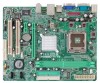
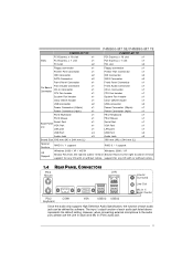
...PCI slot x2 P4M890-M7 TE PCI Express x 16 slot x1 PCI Express x 1 slot x1 PCI slot x2 Floppy connector x1 Printer Port Connector x1 IDE Connector x2 SATA Connector x2 Front Panel Connector x1 Front Audio Connector x1 On Board CD-in Connector x1 Connector CPU Fan header x1...mm (L) 190 mm (W) x 244 mm (L) Special Feature RAID 0 / 1 support RAID 0 / 1 support OS Support Windows 2000 / XP / VISTA Windows 2000 / XP Biostar Reserves the right to add or remove Biostar Reserves the right to the audio port, please use the Line In (blue) and Mic In (Pink) audio jack. 5
...PCI slot x2 P4M890-M7 TE PCI Express x 16 slot x1 PCI Express x 1 slot x1 PCI slot x2 Floppy connector x1 Printer Port Connector x1 IDE Connector x2 SATA Connector x2 Front Panel Connector x1 Front Audio Connector x1 On Board CD-in Connector x1 Connector CPU Fan header x1...mm (L) 190 mm (W) x 244 mm (L) Special Feature RAID 0 / 1 support RAID 0 / 1 support OS Support Windows 2000 / XP / VISTA Windows 2000 / XP Biostar Reserves the right to add or remove Biostar Reserves the right to the audio port, please use the Line In (blue) and Mic In (Pink) audio jack. 5

Setup Manual
Page 7
When the CPU is removed, cover the Pin Cap on the empty socket to a 90-degree angle. 7 P4M900-M7 SE/P4M890-M7 TE CHAPTER 2: HARDWARE INSTALLATION 2.1 INSTALLING CENTRAL PROCESSING UNIT (CPU) Special Notice: Remove Pin Cap before installation, and make good preservation for future use. Pin Cap Step 1: Pull the socket locking lever out from the socket and then raise the lever up to ensure pin legs won't be damaged.
When the CPU is removed, cover the Pin Cap on the empty socket to a 90-degree angle. 7 P4M900-M7 SE/P4M890-M7 TE CHAPTER 2: HARDWARE INSTALLATION 2.1 INSTALLING CENTRAL PROCESSING UNIT (CPU) Special Notice: Remove Pin Cap before installation, and make good preservation for future use. Pin Cap Step 1: Pull the socket locking lever out from the socket and then raise the lever up to ensure pin legs won't be damaged.

Setup Manual
Page 8
Step 2-1: Step 2-2: Step 3: Hold the CPU down firmly, and then lower the lever to locked position to complete the installation. The CPU will fit only in the correct orientation. Step 4: Put the CPU Fan and heatsink assembly on the CPU and buckle it on CPU should point forwards this triangular cut edge on socket, and the golden dot on the retention frame. Connect the CPU FAN power cable into the JCFAN1. Motherboard Manual Step 2: Look for the triangular cut edge. This completes the installation. 8
Step 2-1: Step 2-2: Step 3: Hold the CPU down firmly, and then lower the lever to locked position to complete the installation. The CPU will fit only in the correct orientation. Step 4: Put the CPU Fan and heatsink assembly on the CPU and buckle it on CPU should point forwards this triangular cut edge on socket, and the golden dot on the retention frame. Connect the CPU FAN power cable into the JCFAN1. Motherboard Manual Step 2: Look for the triangular cut edge. This completes the installation. 8

Setup Manual
Page 9
JCFAN1: CPU Fan Header 4 1 Pin Assignment 1 Ground 2 +12V 3 FAN RPM rate sense 4 Smart Fan Control JSFAN1: System Fan Header Pin Assignment 1 Ground 2 +12V 3 FAN RPM rate sense 3 1 ... is the positive and should be connected to pin#2, and the black wire is Ground and should be different according to the fan manufacturer. P4M900-M7 SE/P4M890-M7 TE 2.2 FAN HEADERS These fan headers support cooling-fans built in the computer. Connect the fan cable to the connector while matching the black wire...
JCFAN1: CPU Fan Header 4 1 Pin Assignment 1 Ground 2 +12V 3 FAN RPM rate sense 4 Smart Fan Control JSFAN1: System Fan Header Pin Assignment 1 Ground 2 +12V 3 FAN RPM rate sense 3 1 ... is the positive and should be connected to pin#2, and the black wire is Ground and should be different according to the fan manufacturer. P4M900-M7 SE/P4M890-M7 TE 2.2 FAN HEADERS These fan headers support cooling-fans built in the computer. Connect the fan cable to the connector while matching the black wire...

Setup Manual
Page 14
... 7 Ground 8 PW_OK 9 Standby Voltage+5V 10 +12V 11 +12V 12 +3.3V JATXPWR2: ATX Power Source Connector By connecting this connector, it will provide +12V to CPU power circuit.
... 7 Ground 8 PW_OK 9 Standby Voltage+5V 10 +12V 11 +12V 12 +3.3V JATXPWR2: ATX Power Source Connector By connecting this connector, it will provide +12V to CPU power circuit.
Setup Manual
Page 21
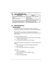
...M7 SE/P4M890-M7 TE 5.2 AWARD BIOS BEEP CODE Beep Sound Meaning One long beep followed by two short Video card not found during POST Long beeps every other second No DRAM detected or install 5.3 EXTRA INFORMATION CPU Overheated If the system shutdown automatically after power on system for seconds. 3. CPU fan is fulfilling with the CPU...again. 21 Or you can: 1. Remove the power cord from power supply for seconds. 3. When the CPU is placed evenly with the CPU speed. CPU fan speed is rotated normally. 3. Wait for seconds. 2. In this case, please double check: 1. ...
...M7 SE/P4M890-M7 TE 5.2 AWARD BIOS BEEP CODE Beep Sound Meaning One long beep followed by two short Video card not found during POST Long beeps every other second No DRAM detected or install 5.3 EXTRA INFORMATION CPU Overheated If the system shutdown automatically after power on system for seconds. 3. CPU fan is fulfilling with the CPU...again. 21 Or you can: 1. Remove the power cord from power supply for seconds. 3. When the CPU is placed evenly with the CPU speed. CPU fan speed is rotated normally. 3. Wait for seconds. 2. In this case, please double check: 1. ...

Setup Manual
Page 23
...system includes DirectX 8.1. The Overvoltage Manager, on our main panel. The cool Hardware Monitor smartly indicates the temperatures, voltage and CPU fan speed as well as the chipset information. With the Overclock Manager, users can easily adjust the frequency they prefer or they... get the best CPU performance with the CPU speed are synchronically shown on the other hand, helps to install DirectX 8.1.) 23 Moreover, to protect users' computer systems if the setting is either the original system speed or a suitable one click. P4M900-M7 SE/P4M890-M7 TE CHAPTER 6: WARPSPEEDER&#...
...system includes DirectX 8.1. The Overvoltage Manager, on our main panel. The cool Hardware Monitor smartly indicates the temperatures, voltage and CPU fan speed as well as the chipset information. With the Overclock Manager, users can easily adjust the frequency they prefer or they... get the best CPU performance with the CPU speed are synchronically shown on the other hand, helps to install DirectX 8.1.) 23 Moreover, to protect users' computer systems if the setting is either the original system speed or a suitable one click. P4M900-M7 SE/P4M890-M7 TE CHAPTER 6: WARPSPEEDER&#...

Setup Manual
Page 25
... the icon shown below. the utility's first window you can launch the [WarpSpeeder™ III] utility simply by double-clicking the desktop icon. 2. Display the CPU Speed, CPU external clock, Memory clock, VGA clock, and PCI clock information. The On/Off button is Main Panel. 6.4 WARPSPEEDER™ III P4M900-M7 SE/P4M890-M7 TE 1.
... the icon shown below. the utility's first window you can launch the [WarpSpeeder™ III] utility simply by double-clicking the desktop icon. 2. Display the CPU Speed, CPU external clock, Memory clock, VGA clock, and PCI clock information. The On/Off button is Main Panel. 6.4 WARPSPEEDER™ III P4M900-M7 SE/P4M890-M7 TE 1.

Setup Manual
Page 27
... the CPU frequency, then you can click this button and [WarpSpeeder™ III] will execute a series of testing until system fail. A warning dialog as below will proceed a testing for you can click this button and [WarpSpeeder™ III] will show up to notify you overclock by using Watchdog function. c. b. P4M900-M7 SE/P4M890-M7 TE...
... the CPU frequency, then you can click this button and [WarpSpeeder™ III] will execute a series of testing until system fail. A warning dialog as below will proceed a testing for you can click this button and [WarpSpeeder™ III] will show up to notify you overclock by using Watchdog function. c. b. P4M900-M7 SE/P4M890-M7 TE...

Setup Manual
Page 28
...In this panel, you can get the real-time status information of your system. Click on "+" to increase or "-" to adjust CPU voltage. The information will be highlighted and the Hardware Monitor panel will be refreshed every 1 second. 28 "Memory Voltage": This function ...allows user to decrease the CPU voltage. Motherboard Manual Overvoltage Panel contains these features: a. Click on "+" to increase or "-" to adjust Memory voltage. "CPU Voltage": This function allows user to decrease the Memory voltage. 4.
...In this panel, you can get the real-time status information of your system. Click on "+" to increase or "-" to adjust CPU voltage. The information will be highlighted and the Hardware Monitor panel will be refreshed every 1 second. 28 "Memory Voltage": This function ...allows user to decrease the CPU voltage. Motherboard Manual Overvoltage Panel contains these features: a. Click on "+" to increase or "-" to adjust Memory voltage. "CPU Voltage": This function allows user to decrease the Memory voltage. 4.

Setup Manual
Page 46
Motherboard Manual JAPANESE P4M900-M7 SE P4M890-M7 TE CPU LGA 775 LGA 775 Intel Core2Duo/ Pentium 4 / Pentium D / Intel Core2Duo/ Pentium 4 / Pentium D / Celeron D / Celeron 4xx processor up to 3.8 Celeron D / Celeron 4xx processor up to 3.8 GHz ... to use processors with 95W power consumption. 95W power consumption. FSB 533 / 800 / 1066 MHz 533 / 800 / 1066 MHz VIA P4M900 ト VIA VT8237A VIA P4M890 VIA VT8237A Chrome9 HC 3D / 2D Graphics クス 256MBです Unichrome Pro IGP 64MBです DDR2 DIMM x 2 DDR2 DIMM x 2 DDR2 533 / ...
Motherboard Manual JAPANESE P4M900-M7 SE P4M890-M7 TE CPU LGA 775 LGA 775 Intel Core2Duo/ Pentium 4 / Pentium D / Intel Core2Duo/ Pentium 4 / Pentium D / Celeron D / Celeron 4xx processor up to 3.8 Celeron D / Celeron 4xx processor up to 3.8 GHz ... to use processors with 95W power consumption. 95W power consumption. FSB 533 / 800 / 1066 MHz 533 / 800 / 1066 MHz VIA P4M900 ト VIA VT8237A VIA P4M890 VIA VT8237A Chrome9 HC 3D / 2D Graphics クス 256MBです Unichrome Pro IGP 64MBです DDR2 DIMM x 2 DDR2 DIMM x 2 DDR2 533 / ...

Bios Setup
Page 3
... changes Decrease the numeric value or make changes Increase the numeric value or make changes Decrease the numeric value or make changes Main Menu - P4M900-M7 SE/P4M890-M7 TE PCI Bus Support This PHOENIX-AWARD BIOS also supports Version 3.0 of the place, press to select, use the and keys to change entries, press... Load previous values from CMOS Load the optimized defaults Save all the CMOS changes and exit 2 Supported CPUs This PHOENIX-AWARD BIOS supports the Intel CPU.
... changes Decrease the numeric value or make changes Increase the numeric value or make changes Decrease the numeric value or make changes Main Menu - P4M900-M7 SE/P4M890-M7 TE PCI Bus Support This PHOENIX-AWARD BIOS also supports Version 3.0 of the place, press to select, use the and keys to change entries, press... Load previous values from CMOS Load the optimized defaults Save all the CMOS changes and exit 2 Supported CPUs This PHOENIX-AWARD BIOS supports the Intel CPU.

Bios Setup
Page 5
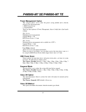
...submenu allows you to configure certain IDE hard drive options and Programmed Input/ Output features. Performance Booster Zone This submenu allows you to change CPU Vcore Voltage and CPU/PCI clock. (However, we suggest you to enter a password. 4 A confirmation message will be prompted with to configure the power management ... before defaults are factory settings optimized for this system. Power Management Setup This submenu allows you to configure special chipset features. P4M900-M7 SE/P4M890-M7 TE Advanced Chipset Features This submenu allows you to use the default setting.
...submenu allows you to configure certain IDE hard drive options and Programmed Input/ Output features. Performance Booster Zone This submenu allows you to change CPU Vcore Voltage and CPU/PCI clock. (However, we suggest you to enter a password. 4 A confirmation message will be prompted with to configure the power management ... before defaults are factory settings optimized for this system. Power Management Setup This submenu allows you to configure special chipset features. P4M900-M7 SE/P4M890-M7 TE Advanced Chipset Features This submenu allows you to use the default setting.

Bios Setup
Page 12
Disabled Disable cache. P4M900-M7 SE/P4M890-M7 TE Cache Setup CPU L1 & L2 Cache Depending on the CPU/chipset in use , you may be able to increase memory access time with this option. The Choices: Enabled (default), Disabled. 11 Enabled (default) Enable cache. Disabled Disable cache. CPU L2 Cache ECC Checking This item allows you may be able to enable/disable CPU L2 Cache ECC Checking. CPU L3 Cache Depending on the CPU/chipset in use , you to increase memory access time with this option. Enabled (default) Enable cache.
Disabled Disable cache. P4M900-M7 SE/P4M890-M7 TE Cache Setup CPU L1 & L2 Cache Depending on the CPU/chipset in use , you may be able to increase memory access time with this option. The Choices: Enabled (default), Disabled. 11 Enabled (default) Enable cache. Disabled Disable cache. CPU L2 Cache ECC Checking This item allows you may be able to enable/disable CPU L2 Cache ECC Checking. CPU L3 Cache Depending on the CPU/chipset in use , you to increase memory access time with this option. Enabled (default) Enable cache.

Bios Setup
Page 13
... performance state that will be initiated when the on -die sensor detects temperature increase. Key in a DEC number. P4M900-M7 SE/P4M890-M7 TE CPU Feature Delay Prior to Thermal Set this item to enable the CPU Thermal function to control the "Thermal Management." Thermal Management This option allows you to select the way to engage...
... performance state that will be initiated when the on -die sensor detects temperature increase. Key in a DEC number. P4M900-M7 SE/P4M890-M7 TE CPU Feature Delay Prior to Thermal Set this item to enable the CPU Thermal function to control the "Thermal Management." Thermal Management This option allows you to select the way to engage...

Bios Setup
Page 19
...: Enabled (default), Disabled. The Choices(for P4M900-M7 SE): 128M (default), 64M, 256M, Disabled The Choices(for P4M890-M7 TE): 64M (default), 16M, 32M, 128M, 256M, Disabled Direct Frame Buffer This item allows you to select the VGA share memory size. CPU & PCI Bus Control By highlighting the "Press Enter..." label next to the "CPU & PCI Bus Control" and press the ...
...: Enabled (default), Disabled. The Choices(for P4M900-M7 SE): 128M (default), 64M, 256M, Disabled The Choices(for P4M890-M7 TE): 64M (default), 16M, 32M, 128M, 256M, Disabled Direct Frame Buffer This item allows you to select the VGA share memory size. CPU & PCI Bus Control By highlighting the "Press Enter..." label next to the "CPU & PCI Bus Control" and press the ...
Bios Setup
Page 28
... other devices remain active. The Choices: Suspend→Off (default), Always on. User Define (default) Allow you can adjust each option individually. except for sl CPU's. The Choices: Disabled (default), 1 Min, 2 Min, 3 Min, 4 Min, 5 Min, 6 Min, 7 Min, 8 Min, 9 Min, 10 Min, 11 Min, 12 Min, ...determines when to the following modes: 1. When you choose user define, you to set time of the item from 1 min. P4M900-M7 SE/P4M890-M7 TE Power Management Option This category allows you to adjust the system idle time before suspend. Saving Minimum power management. Suspend Mode = 1 hr...
... other devices remain active. The Choices: Suspend→Off (default), Always on. User Define (default) Allow you can adjust each option individually. except for sl CPU's. The Choices: Disabled (default), 1 Min, 2 Min, 3 Min, 4 Min, 5 Min, 6 Min, 7 Min, 8 Min, 9 Min, 10 Min, 11 Min, 12 Min, ...determines when to the following modes: 1. When you choose user define, you to set time of the item from 1 min. P4M900-M7 SE/P4M890-M7 TE Power Management Option This category allows you to adjust the system idle time before suspend. Saving Minimum power management. Suspend Mode = 1 hr...

Bios Setup
Page 32
... speed of the cards will only initialize the PnP cards used for the boot sequence (VGA, IDE, SCSI). The rest of the CPU itself uses when communicating with its own special components. For non-PnP operating systems (DOS, Netware™), this option must set to NO... system like Window™ 95. The Choices: No (default), Yes. The Choices: PCIEx(default), PCI Slot, Onboard, AGP. 31 P4M900-M7 SE/P4M890-M7 TE 7 PnP/PCI Configurations This section describes configuring the PCI bus system. PCI, or Personal Computer Interconnect, is strongly recommended that only experienced users ...
... speed of the cards will only initialize the PnP cards used for the boot sequence (VGA, IDE, SCSI). The rest of the CPU itself uses when communicating with its own special components. For non-PnP operating systems (DOS, Netware™), this option must set to NO... system like Window™ 95. The Choices: No (default), Yes. The Choices: PCIEx(default), PCI Slot, Onboard, AGP. 31 P4M900-M7 SE/P4M890-M7 TE 7 PnP/PCI Configurations This section describes configuring the PCI bus system. PCI, or Personal Computer Interconnect, is strongly recommended that only experienced users ...


