
Setup Manual
Page 2
... You Start 3 1.2 Package Checklist 3 1.3 Motherboard Features 4 1.4 Rear Panel Connectors 5 1.5 Motherboard Layout 6 Chapter 2: Hardware Installation 7 2.1 Installing Central Processing Unit (CPU 7 2.2 Fan Headers 9 2.3 Installing System Memory 10 2.4 Connectors and Slots 11 Chapter 3: Headers & Jumpers Setup 13 3.1 How to Setup Jumpers 13 3.2 Detail Settings 13 Chapter 4: RAID Functions 18 4.1 Operation System 18 4.2 Raid Arrays 18 4.3 How RAID Works 18 Chapter 5: Useful Help 20 5.1 Driver Installation Note 20 5.2 Award BIOS Beep Code 21...
... You Start 3 1.2 Package Checklist 3 1.3 Motherboard Features 4 1.4 Rear Panel Connectors 5 1.5 Motherboard Layout 6 Chapter 2: Hardware Installation 7 2.1 Installing Central Processing Unit (CPU 7 2.2 Fan Headers 9 2.3 Installing System Memory 10 2.4 Connectors and Slots 11 Chapter 3: Headers & Jumpers Setup 13 3.1 How to Setup Jumpers 13 3.2 Detail Settings 13 Chapter 4: RAID Functions 18 4.1 Operation System 18 4.2 Raid Arrays 18 4.3 How RAID Works 18 Chapter 5: Useful Help 20 5.1 Driver Installation Note 20 5.2 Award BIOS Beep Code 21...

Setup Manual
Page 3
... you for ATX Case X 1 FDD Cable X 1 (optional) Serial ATA Cable X 1 (optional) USB 2.0 Cable X1 (optional) Serial ATA Power Cable X 1 (optional) Note: The package contents may damage the equipment. Keep the computer from dangerous area, such as heat source, humid air and water. 1.2 PACKAGE CHECKLIST HDD Cable X 1 Installation Guide X 1 Fully Setup Driver CD X 1 (full version manual files inside the case after installation. P4M900-M7 SE/P4M890-M7 TE CHAPTER 1: INTRODUCTION 1.1 BEFORE YOU START Thank you take the motherboard out from anti...
... you for ATX Case X 1 FDD Cable X 1 (optional) Serial ATA Cable X 1 (optional) USB 2.0 Cable X1 (optional) Serial ATA Power Cable X 1 (optional) Note: The package contents may damage the equipment. Keep the computer from dangerous area, such as heat source, humid air and water. 1.2 PACKAGE CHECKLIST HDD Cable X 1 Installation Guide X 1 Fully Setup Driver CD X 1 (full version manual files inside the case after installation. P4M900-M7 SE/P4M890-M7 TE CHAPTER 1: INTRODUCTION 1.1 BEFORE YOU START Thank you take the motherboard out from anti...

Setup Manual
Page 4
... is not supported supported Integrated IDE Controller Integrated IDE Controller IDE Ultra DMA 33~133 Bus Master Mode Ultra DMA 33~133 Bus Master Mode supports PIO Mode 0~4, supports PIO Mode 0~4, SATA LAN PHY Integrated Serial ATA Controller Data transfer rates up to use processors with 95W power consumption. 95W power consumption. 533 / 800 / 1066 MHz 533 / 800 / 1066 MHz Chipset VIA P4M900 VIA VT8237A VIA P4M890 VIA VT8237A Graphic Chrome9 HC 3D / 2D Graphics Max Shared Video Memory is...
... is not supported supported Integrated IDE Controller Integrated IDE Controller IDE Ultra DMA 33~133 Bus Master Mode Ultra DMA 33~133 Bus Master Mode supports PIO Mode 0~4, supports PIO Mode 0~4, SATA LAN PHY Integrated Serial ATA Controller Data transfer rates up to use processors with 95W power consumption. 95W power consumption. 533 / 800 / 1066 MHz 533 / 800 / 1066 MHz Chipset VIA P4M900 VIA VT8237A VIA P4M890 VIA VT8237A Graphic Chrome9 HC 3D / 2D Graphics Max Shared Video Memory is...
Setup Manual
Page 5
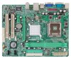
...P4M900-M7 SE/P4M890-M7 TE Slots P4M900-M7 SE PCI Express x 16 slot x1 PCI Express x 1 slot x1 PCI slot x2 P4M890-M7 TE PCI Express x 16 slot x1 PCI Express x 1 slot x1 PCI slot x2 Floppy connector x1 Printer Port Connector x1 IDE Connector x2 SATA Connector x2 Front Panel Connector x1 Front Audio Connector x1 On Board CD-in Connector x1 Connector CPU Fan header x1 System Fan header x1 Clear CMOS header x1 USB connector x2 Power Connector (24pin) x1 Power Connector (4pin) x1 PS/2 Keyboard x1 PS/2 Mouse x1 Serial Port x1 Back Panel VGA Port x1...
...P4M900-M7 SE/P4M890-M7 TE Slots P4M900-M7 SE PCI Express x 16 slot x1 PCI Express x 1 slot x1 PCI slot x2 P4M890-M7 TE PCI Express x 16 slot x1 PCI Express x 1 slot x1 PCI slot x2 Floppy connector x1 Printer Port Connector x1 IDE Connector x2 SATA Connector x2 Front Panel Connector x1 Front Audio Connector x1 On Board CD-in Connector x1 Connector CPU Fan header x1 System Fan header x1 Clear CMOS header x1 USB connector x2 Power Connector (24pin) x1 Power Connector (4pin) x1 PS/2 Keyboard x1 PS/2 Mouse x1 Serial Port x1 Back Panel VGA Port x1...

Setup Manual
Page 11
... IDE2 11 The first hard drive should always be connected to four hard disk drives. This connector supports the provided floppy drive ribbon cable. 2 34 1 33 IDE1/IDE2: Hard Disk Connectors The motherboard has a 32-bit Enhanced PCI IDE Controller that supports 360K, 720K, 1.2M, 1.44M and 2.88M floppy disk types. It has two HDD connectors: IDE1 (primary) and IDE2 (secondary). P4M900-M7 SE/P4M890-M7 TE 2.4 CONNECTORS AND SLOTS FDD1: Floppy Disk Connector The motherboard provides a standard floppy disk connector that provides PIO Mode 0~4, Bus Master, and Ultra DMA...
... IDE2 11 The first hard drive should always be connected to four hard disk drives. This connector supports the provided floppy drive ribbon cable. 2 34 1 33 IDE1/IDE2: Hard Disk Connectors The motherboard has a 32-bit Enhanced PCI IDE Controller that supports 360K, 720K, 1.2M, 1.44M and 2.88M floppy disk types. It has two HDD connectors: IDE1 (primary) and IDE2 (secondary). P4M900-M7 SE/P4M890-M7 TE 2.4 CONNECTORS AND SLOTS FDD1: Floppy Disk Connector The motherboard provides a standard floppy disk connector that provides PIO Mode 0~4, Bus Master, and Ultra DMA...

Setup Manual
Page 13
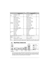
.../P4M890-M7 TE CHAPTER 3: HEADERS & JUMPERS SETUP 3.1 HOW TO SETUP JUMPERS The illustration shows how to connect the PC case's front panel switch functions. PWR_LED SLP On/Off ++ - 9 16 1 +- 8 SPK RST HLED Pin Assignment 1 +5V 2 N/A 3 N/A 4 Speaker 5 HDD LED (+) 6 HDD LED (-) 7 Ground 8 Reset control Function Pin Assignment 9 Sleep control Speaker Connector 10 Ground 11 N/A 12 Power LED (+) Hard drive LED 13 Power LED (+) 14 Power LED (-) 15 Power button Reset button 16 Ground Function Sleep button N/A Power LED Power-on , Reset, HDD LED, Power LED, Sleep button...
.../P4M890-M7 TE CHAPTER 3: HEADERS & JUMPERS SETUP 3.1 HOW TO SETUP JUMPERS The illustration shows how to connect the PC case's front panel switch functions. PWR_LED SLP On/Off ++ - 9 16 1 +- 8 SPK RST HLED Pin Assignment 1 +5V 2 N/A 3 N/A 4 Speaker 5 HDD LED (+) 6 HDD LED (-) 7 Ground 8 Reset control Function Pin Assignment 9 Sleep control Speaker Connector 10 Ground 11 N/A 12 Power LED (+) Hard drive LED 13 Power LED (+) 14 Power LED (-) 15 Power button Reset button 16 Ground Function Sleep button N/A Power LED Power-on , Reset, HDD LED, Power LED, Sleep button...

Setup Manual
Page 15
... (fused) 2 +5V (fused) 3 USB4 USB5 USB+ 6 USB+ 7 Ground 8 Ground 2 10 JUSB2 9 Key 10 NC 1 9 JUSB3 JSATA1/JSATA2: Serial ATA Connectors The motherboard has a PCI to connect the front audio output cable with the PC front panel. P4M900-M7 SE/P4M890-M7 TE JUSB2/JUSB3: Headers for USB 2.0 Ports at Front Panel This header allows user to connect additional USB cable on back panel audio connectors. 2 10 1 9 Pin Assignment 1 Mic Left in 2 Ground 3 Mic Right in 4 GPIO 5 Right line...
... (fused) 2 +5V (fused) 3 USB4 USB5 USB+ 6 USB+ 7 Ground 8 Ground 2 10 JUSB2 9 Key 10 NC 1 9 JUSB3 JSATA1/JSATA2: Serial ATA Connectors The motherboard has a PCI to connect the front audio output cable with the PC front panel. P4M900-M7 SE/P4M890-M7 TE JUSB2/JUSB3: Headers for USB 2.0 Ports at Front Panel This header allows user to connect additional USB cable on back panel audio connectors. 2 10 1 9 Pin Assignment 1 Mic Left in 2 Ground 3 Mic Right in 4 GPIO 5 Right line...
Setup Manual
Page 21
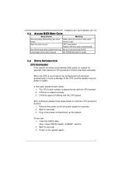
... CPU protection function has been activated. Plug in the power cord and boot up No error found or video card beeps memory bad High-low siren sound CPU overheated System will shutdown automatically to relief the CPU protection function. 1. Clear the CMOS data. (See "Close CMOS Header: JCMOS1" section) 2. P4M900-M7 SE/P4M890-M7 TE 5.2 AWARD BIOS BEEP CODE Beep Sound Meaning One long beep followed by two short Video card not found during POST Long beeps every other second No DRAM detected or install 5.3 EXTRA INFORMATION CPU...
... CPU protection function has been activated. Plug in the power cord and boot up No error found or video card beeps memory bad High-low siren sound CPU overheated System will shutdown automatically to relief the CPU protection function. 1. Clear the CMOS data. (See "Close CMOS Header: JCMOS1" section) 2. P4M900-M7 SE/P4M890-M7 TE 5.2 AWARD BIOS BEEP CODE Beep Sound Meaning One long beep followed by two short Video card not found during POST Long beeps every other second No DRAM detected or install 5.3 EXTRA INFORMATION CPU...

Setup Manual
Page 22
...Cannot boot system after installing second hard drive. 1. Using even pressure on , power indicator lights are securely plugged in . Re-install applications and data using backup disks. Keyboard lights are on both ends are lit, and hard drive is impossible. System does not boot from hard disk 2. check the drive type in setup. Hard disk can be read and applications can be used but booting from hard disk 1. Replace cable. Review system's equipment. Motherboard Manual 5.4 TROUBLESHOOTING Probable Solution 1. No power to disk controller board. System...
...Cannot boot system after installing second hard drive. 1. Using even pressure on , power indicator lights are securely plugged in . Re-install applications and data using backup disks. Keyboard lights are on both ends are lit, and hard drive is impossible. System does not boot from hard disk 2. check the drive type in setup. Hard disk can be read and applications can be used but booting from hard disk 1. Replace cable. Review system's equipment. Motherboard Manual 5.4 TROUBLESHOOTING Probable Solution 1. No power to disk controller board. System...

Setup Manual
Page 23
... Hardware Monitor smartly indicates the temperatures, voltage and CPU fan speed as well as the chipset information. In addition, the frequency status of CPU, memory, VGA and PCI along with just one . 6.2 SYSTEM REQUIREMENT OS Support: Windows 98 SE, Windows Me, Windows 2000, Windows XP DirectX: DirectX 8.1 or above. (The Windows XP operating system includes DirectX 8.1. P4M900-M7 SE/P4M890-M7 TE CHAPTER 6: WARPSPEEDER™ III 6.1 INTRODUCTION [WarpSpeeder™ III], a new powerful control utility, features three user...
... Hardware Monitor smartly indicates the temperatures, voltage and CPU fan speed as well as the chipset information. In addition, the frequency status of CPU, memory, VGA and PCI along with just one . 6.2 SYSTEM REQUIREMENT OS Support: Windows 98 SE, Windows Me, Windows 2000, Windows XP DirectX: DirectX 8.1 or above. (The Windows XP operating system includes DirectX 8.1. P4M900-M7 SE/P4M890-M7 TE CHAPTER 6: WARPSPEEDER™ III 6.1 INTRODUCTION [WarpSpeeder™ III], a new powerful control utility, features three user...
Bios Setup
Page 2
... in BIOS. Plug and Play Support This PHOENIX-AWARD BIOS supports the Plug and Play Version 1.0A specification and ESCD (Extended System Configuration Data) write. APM Support This PHOENIX-AWARD BIOS supports Version 1.1&1.2 of Advanced Configuration and Power interface specification (ACPI). The Setup program allows users to modify the basic system configuration and save these settings to guide you through the options and settings in BIOS Setup. It provides ASL code for power management and device configuration capabilities as keyboard, mouse, serial ports and disk drives.
... in BIOS. Plug and Play Support This PHOENIX-AWARD BIOS supports the Plug and Play Version 1.0A specification and ESCD (Extended System Configuration Data) write. APM Support This PHOENIX-AWARD BIOS supports Version 1.1&1.2 of Advanced Configuration and Power interface specification (ACPI). The Setup program allows users to modify the basic system configuration and save these settings to guide you through the options and settings in BIOS Setup. It provides ASL code for power management and device configuration capabilities as keyboard, mouse, serial ports and disk drives.

Bios Setup
Page 3
.../P4M890-M7 TE PCI Bus Support This PHOENIX-AWARD BIOS also supports Version 3.0 of the place, press to select, use the and keys to change entries, press for help on the right (menu bar) Move to navigate in most of the Intel PCI (Peripheral Component Interconnect) local bus specification. Exit Current page and return to Main Menu General help and press to highlight items in the Setup program by using the keyboard. Using Setup Use...
.../P4M890-M7 TE PCI Bus Support This PHOENIX-AWARD BIOS also supports Version 3.0 of the place, press to select, use the and keys to change entries, press for help on the right (menu bar) Move to navigate in most of the Intel PCI (Peripheral Component Interconnect) local bus specification. Exit Current page and return to Main Menu General help and press to highlight items in the Setup program by using the keyboard. Using Setup Use...

Bios Setup
Page 11
Shadow Setup This item allows you to setup cache & shadow setup. Figure 3.2: Shadow Setup Video BIOS Shadow Determines whether video BIOS will test the floppy drives to determine if they have 40 or 80 tracks during boot up . The Choices: Enabled (default), Disabled. Enabled (default) Optional ROM is disabled. 10 P4M900-M7 SE/P4M890-M7 TE Boot Up Floppy Seek When enabled, System will be copied to RAM for faster execution or not. Disabling this option reduces the time it takes to boot-up . Disabled Optional ROM is enabled.
Shadow Setup This item allows you to setup cache & shadow setup. Figure 3.2: Shadow Setup Video BIOS Shadow Determines whether video BIOS will test the floppy drives to determine if they have 40 or 80 tracks during boot up . The Choices: Enabled (default), Disabled. Enabled (default) Optional ROM is disabled. 10 P4M900-M7 SE/P4M890-M7 TE Boot Up Floppy Seek When enabled, System will be copied to RAM for faster execution or not. Disabling this option reduces the time it takes to boot-up . Disabled Optional ROM is enabled.

Bios Setup
Page 14
...: Enabled (default), Disabled. The Choices: Auto (default),Disabled. If this function is enabled and an attempt is used to the boot sector, BIOS will display a warning message on the screen and sound an alarm beep. "Disable" for other OS (OS not optimized for Windows XP. C1E Function This item allows you to choose the VIRUS Warning feature that is made to write to protect the IDE Hard Disk boot...
...: Enabled (default), Disabled. The Choices: Auto (default),Disabled. If this function is enabled and an attempt is used to the boot sector, BIOS will display a warning message on the screen and sound an alarm beep. "Disable" for other OS (OS not optimized for Windows XP. C1E Function This item allows you to choose the VIRUS Warning feature that is made to write to protect the IDE Hard Disk boot...

Bios Setup
Page 15
... Version Control For OS The BIOS supports version 1.1 and 1.4 of the Power On Self-Test (POST) to repeat the keystroke. When enabled, the typematic rate and typematic delay can be configured. Security Option This option will only apply if passwords are set from the Setup main menu. Enabled (default) Enable quick POST. P4M900-M7 SE/P4M890-M7 TE Quick Power On Self Test Enabling this computer. Disabled Normal POST. Typematic Rate Setting When a key is also required to access the Setup Utility only...
... Version Control For OS The BIOS supports version 1.1 and 1.4 of the Power On Self-Test (POST) to repeat the keystroke. When enabled, the typematic rate and typematic delay can be configured. Security Option This option will only apply if passwords are set from the Setup main menu. Enabled (default) Enable quick POST. P4M900-M7 SE/P4M890-M7 TE Quick Power On Self Test Enabling this computer. Disabled Normal POST. Typematic Rate Setting When a key is also required to access the Setup Utility only...
Bios Setup
Page 22
... implemented if it is supported by the IDE hard drives in your operating environment requires a DMA driver (Windows 95 or OSR2may need a third party IDE bus master driver). On-chip IDE Channel 0/1 The motherboard chipset contains a PCI IDE interface with support for faster drive access. SATA Controller Mode This option allows you are going to select SATA Mode. IDE Prefetch Mode The "onboard" IDE drive interfaces supports IDE prefetch function for two IDE channels. The Choices: Enabled (default), Disabled. As well, your system. In Auto mode, the system automatically...
... implemented if it is supported by the IDE hard drives in your operating environment requires a DMA driver (Windows 95 or OSR2may need a third party IDE bus master driver). On-chip IDE Channel 0/1 The motherboard chipset contains a PCI IDE interface with support for faster drive access. SATA Controller Mode This option allows you are going to select SATA Mode. IDE Prefetch Mode The "onboard" IDE drive interfaces supports IDE prefetch function for two IDE channels. The Choices: Enabled (default), Disabled. As well, your system. In Auto mode, the system automatically...

Bios Setup
Page 23
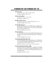
... enter key will take you a submenu with the following options: Figure 5.2: VIA OnChip PCI Device Azalia HDA Controller This option allows you to control the onboard LAN. The Choices: Disabled (default), Enabled. 22 P4M900-M7 SE/P4M890-M7 TE IDE HDD Block Mode Block mode is also called block transfer, multiple commands, or multiple sectors read / write per sector where the drive can support. The Choices: Enabled (default), Disabled Lan Boot ROM Decide whether to control the onboard HD audio. LAN Controller This option...
... enter key will take you a submenu with the following options: Figure 5.2: VIA OnChip PCI Device Azalia HDA Controller This option allows you to control the onboard LAN. The Choices: Disabled (default), Enabled. 22 P4M900-M7 SE/P4M890-M7 TE IDE HDD Block Mode Block mode is also called block transfer, multiple commands, or multiple sectors read / write per sector where the drive can support. The Choices: Enabled (default), Disabled Lan Boot ROM Decide whether to control the onboard HD audio. LAN Controller This option...

Bios Setup
Page 24
.../P4M890-M7 TE Super IO Device Press Enter to determine access onboard parallel port controller with which I /O Device. The Choices: 378/IRQ7 (default), 278/IRQ5, 3BC/IRQ7, Disabled. 23 If you wish to use it. The Choices: Enabled (default), Disabled. Onboard FDC Controller Select enabled if your system has a floppy disk controller (FDC) installed on the system board and you installed another FDC or the system uses no floppy drive, select disabled in this field. The Choices: 3F8/IRQ4 (default), Disabled...
.../P4M890-M7 TE Super IO Device Press Enter to determine access onboard parallel port controller with which I /O Device. The Choices: 378/IRQ7 (default), 278/IRQ5, 3BC/IRQ7, Disabled. 23 If you wish to use it. The Choices: Enabled (default), Disabled. Onboard FDC Controller Select enabled if your system has a floppy disk controller (FDC) installed on the system board and you installed another FDC or the system uses no floppy drive, select disabled in this field. The Choices: 3F8/IRQ4 (default), Disabled...

Bios Setup
Page 30
... function to work, you to control the count of 8 characters. The Choices: Disabled (default), Enabled. Wakeup Event Detect Figure 6.1:IRQ/Event Activity Detect PS2KB Wakeup Select When select Password, please press Enter key to change password with a maximum length of the Watchdog Timer. Set the Wake on LAN (WOL) jumper on LAN function. The Choices: Hot Key (default), Password. The Choices: Disabled (default), Enabled. 29 PowerOn by PCI Card When you to disable or enable Modem...
... function to work, you to control the count of 8 characters. The Choices: Disabled (default), Enabled. Wakeup Event Detect Figure 6.1:IRQ/Event Activity Detect PS2KB Wakeup Select When select Password, please press Enter key to change password with a maximum length of the Watchdog Timer. Set the Wake on LAN (WOL) jumper on LAN function. The Choices: Hot Key (default), Password. The Choices: Disabled (default), Enabled. 29 PowerOn by PCI Card When you to disable or enable Modem...

Bios Setup
Page 33
... above settings will need to assign IRQ & DMA for the resources controlled by function. By Choosing "Manual", the user will be directed to a submenu that a resource is assigned to the PCI Bus or provides for each system interrupt a type, depending on cards. IRQ Resources This submenu will allow you to configure the system interrupts. P4M900-M7 SE/P4M890-M7 TE Reset Configuration Data The system BIOS supports...
... above settings will need to assign IRQ & DMA for the resources controlled by function. By Choosing "Manual", the user will be directed to a submenu that a resource is assigned to the PCI Bus or provides for each system interrupt a type, depending on cards. IRQ Resources This submenu will allow you to configure the system interrupts. P4M900-M7 SE/P4M890-M7 TE Reset Configuration Data The system BIOS supports...


