
Setup Manual
Page 2
Table of Contents Chapter 1: Introduction 3 1.1 Before You Start 3 1.2 Package Checklist 3 1.3 Motherboard Features 4 1.4 Rear Panel Connectors 5 1.5 Motherboard Layout 6 Chapter 2: Hardware Installation 7 2.1 Installing Central Processing Unit (CPU 7 2.2 Fan Headers 9 2.3 Installing System Memory 10 2.4 Connectors and Slots 11 Chapter 3: Headers & Jumpers Setup 13 3.1 How ...
Table of Contents Chapter 1: Introduction 3 1.1 Before You Start 3 1.2 Package Checklist 3 1.3 Motherboard Features 4 1.4 Rear Panel Connectors 5 1.5 Motherboard Layout 6 Chapter 2: Hardware Installation 7 2.1 Installing Central Processing Unit (CPU 7 2.2 Fan Headers 9 2.3 Installing System Memory 10 2.4 Connectors and Slots 11 Chapter 3: Headers & Jumpers Setup 13 3.1 How ...

Setup Manual
Page 3
... before operation. Before you for choosing our product. P4M900-M7 SE/P4M890-M7 TE CHAPTER 1: INTRODUCTION 1.1 BEFORE YOU START Thank you take the motherboard out from anti-static bag, ground yourself properly by area or your motherboard version. 3 Hold the board on the edge, do not try ... use grounded wrist strap to remove the static charge. Avoid touching the components on motherboard or the rear side of the board unless necessary. Before you start installing the motherboard, please make sure you follow the instructions below: Prepare a dry and stable working...
... before operation. Before you for choosing our product. P4M900-M7 SE/P4M890-M7 TE CHAPTER 1: INTRODUCTION 1.1 BEFORE YOU START Thank you take the motherboard out from anti-static bag, ground yourself properly by area or your motherboard version. 3 Hold the board on the edge, do not try ... use grounded wrist strap to remove the static charge. Avoid touching the components on motherboard or the rear side of the board unless necessary. Before you start installing the motherboard, please make sure you follow the instructions below: Prepare a dry and stable working...

Setup Manual
Page 4
... Integrated Serial ATA Controller Data transfer rates up to use processors with *It is recommended to 1.5 Gb/s. SATA Version 1.0 specification compliant. Motherboard Manual 1.3 MOTHERBOARD FEATURES CPU FSB P4M900-M7 SE P4M890-M7 TE LGA 775 LGA 775 Intel Core2Duo/ Pentium 4 / Pentium D / Intel Core2Duo/ Pentium 4 / Pentium D / Celeron D / Celeron.... 95W power consumption. 533 / 800 / 1066 MHz 533 / 800 / 1066 MHz Chipset VIA P4M900 VIA VT8237A VIA P4M890 VIA VT8237A Graphic Chrome9 HC 3D / 2D Graphics Max Shared Video Memory is 256 MB Unichrome Pro IGP Max Shared Video...
... Integrated Serial ATA Controller Data transfer rates up to use processors with *It is recommended to 1.5 Gb/s. SATA Version 1.0 specification compliant. Motherboard Manual 1.3 MOTHERBOARD FEATURES CPU FSB P4M900-M7 SE P4M890-M7 TE LGA 775 LGA 775 Intel Core2Duo/ Pentium 4 / Pentium D / Intel Core2Duo/ Pentium 4 / Pentium D / Celeron D / Celeron.... 95W power consumption. 533 / 800 / 1066 MHz 533 / 800 / 1066 MHz Chipset VIA P4M900 VIA VT8237A VIA P4M890 VIA VT8237A Graphic Chrome9 HC 3D / 2D Graphics Max Shared Video Memory is 256 MB Unichrome Pro IGP Max Shared Video...

Setup Manual
Page 6
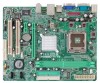
Motherboard Manual 1.5 MOTHERBOARD LAYOUT JKBMS1 LGA775 JCFAN1 COJMC1OM1 CPU1 JATXPWR1 JVGA1 DIMM1 DIMM2 JPRNT1 JUSB1 JUSBLAN1 JATXPWR2 JAUDIO1 LAN P4M900 or P4M890 PCI-EX16 Super I/O BAT1 PCI-EX1_1 JCDIN1 Codec JAUDIOF1 PCI1 PCI2 BIOS JUSB2 JUSB3 FDD1 Note: ■ rep resen ts th e 1 st pin. 6 VIA VT8237A JSATA2 JSATA1 JCMOS1 JPANEL1 JSFAN1 IDE1 IDE2
Motherboard Manual 1.5 MOTHERBOARD LAYOUT JKBMS1 LGA775 JCFAN1 COJMC1OM1 CPU1 JATXPWR1 JVGA1 DIMM1 DIMM2 JPRNT1 JUSB1 JUSBLAN1 JATXPWR2 JAUDIO1 LAN P4M900 or P4M890 PCI-EX16 Super I/O BAT1 PCI-EX1_1 JCDIN1 Codec JAUDIOF1 PCI1 PCI2 BIOS JUSB2 JUSB3 FDD1 Note: ■ rep resen ts th e 1 st pin. 6 VIA VT8237A JSATA2 JSATA1 JCMOS1 JPANEL1 JSFAN1 IDE1 IDE2

Setup Manual
Page 8
The CPU will fit only in the correct orientation. Step 2-1: Step 2-2: Step 3: Hold the CPU down firmly, and then lower the lever to locked position to complete the installation. Step 4: Put the CPU Fan and heatsink assembly on the CPU and buckle it on CPU should point forwards this triangular cut edge on socket, and the golden dot on the retention frame. Connect the CPU FAN power cable into the JCFAN1. This completes the installation. 8 Motherboard Manual Step 2: Look for the triangular cut edge.
The CPU will fit only in the correct orientation. Step 2-1: Step 2-2: Step 3: Hold the CPU down firmly, and then lower the lever to locked position to complete the installation. Step 4: Put the CPU Fan and heatsink assembly on the CPU and buckle it on CPU should point forwards this triangular cut edge on socket, and the golden dot on the retention frame. Connect the CPU FAN power cable into the JCFAN1. This completes the installation. 8 Motherboard Manual Step 2: Look for the triangular cut edge.

Setup Manual
Page 10
Insert the DIMM vertically and firmly into the slot until the retaining chip snap back in place and the DIMM is 4GB. 10 Unlock a DIMM slot by pressing the retaining clips outward. Align a DIMM on the slot such that the notch on the DIMM matches the break on the Slot. 2. B. Motherboard Manual 2.3 INSTALLING SYSTEM MEMORY A. Memory Capacity DIMM Socket Location DDR Module DIMM1 256MB/512MB/1GB/2GB DIMM2 256MB/512MB/1GB/2GB Total Memory Size Max is properly seated. Memory Modules DIMM1 DIMM2 1.
Insert the DIMM vertically and firmly into the slot until the retaining chip snap back in place and the DIMM is 4GB. 10 Unlock a DIMM slot by pressing the retaining clips outward. Align a DIMM on the slot such that the notch on the DIMM matches the break on the Slot. 2. B. Motherboard Manual 2.3 INSTALLING SYSTEM MEMORY A. Memory Capacity DIMM Socket Location DDR Module DIMM1 256MB/512MB/1GB/2GB DIMM2 256MB/512MB/1GB/2GB Total Memory Size Max is properly seated. Memory Modules DIMM1 DIMM2 1.

Setup Manual
Page 11
... drive ribbon cable. 2 34 1 33 IDE1/IDE2: Hard Disk Connectors The motherboard has a 32-bit Enhanced PCI IDE Controller that supports 360K, 720K, 1.2M, 1.44M and 2.88M floppy disk types. P4M900-M7 SE/P4M890-M7 TE 2.4 CONNECTORS AND SLOTS FDD1: Floppy Disk Connector The motherboard provides a standard floppy disk connector that provides PIO Mode 0~4, Bus Master...
... drive ribbon cable. 2 34 1 33 IDE1/IDE2: Hard Disk Connectors The motherboard has a 32-bit Enhanced PCI IDE Controller that supports 360K, 720K, 1.2M, 1.44M and 2.88M floppy disk types. P4M900-M7 SE/P4M890-M7 TE 2.4 CONNECTORS AND SLOTS FDD1: Floppy Disk Connector The motherboard provides a standard floppy disk connector that provides PIO Mode 0~4, Bus Master...

Setup Manual
Page 12
... over the traditional PCI architecture. PCI-EX1_1: PCI-Express x1 Slot - PCI1 PCI2 12 PCI-EX16 PCI-EX1_1 PCI1/PCI2: Peripheral Component Interconnect Slots This motherboard is designated as 32 bits. PCI-Express supports a raw bit-rate of 4GB/s simultaneously per direction; 500MB/s in total...
... over the traditional PCI architecture. PCI-EX1_1: PCI-Express x1 Slot - PCI1 PCI2 12 PCI-EX16 PCI-EX1_1 PCI1/PCI2: Peripheral Component Interconnect Slots This motherboard is designated as 32 bits. PCI-Express supports a raw bit-rate of 4GB/s simultaneously per direction; 500MB/s in total...

Setup Manual
Page 14
Motherboard Manual ATX Power Source Connector: JATXPWR1 JATXPWR1 allows user to connect 24-pin power connector on the ATX power supply. 12 24 Pin Assignment 13 +3....
Motherboard Manual ATX Power Source Connector: JATXPWR1 JATXPWR1 allows user to connect 24-pin power connector on the ATX power supply. 12 24 Pin Assignment 13 +3....

Setup Manual
Page 15
...5V (fused) 2 +5V (fused) 3 USB4 USB5 USB+ 6 USB+ 7 Ground 8 Ground 2 10 JUSB2 9 Key 10 NC 1 9 JUSB3 JSATA1/JSATA2: Serial ATA Connectors The motherboard has a PCI to connect the front audio output cable with the PC front panel. JSATA2 7 41 14 7 Pin Assignment 1 Ground 2 TX+ 3 TX4 Ground 5 RX6 RX+ 7 ...USB card reader. It will disable the output on the PC front panel, and also can be connected with transfer rate of 1.5Gb/s. P4M900-M7 SE/P4M890-M7 TE JUSB2/JUSB3: Headers for USB 2.0 Ports at Front Panel This header allows user to connect additional USB cable on back panel audio connectors. ...
...5V (fused) 2 +5V (fused) 3 USB4 USB5 USB+ 6 USB+ 7 Ground 8 Ground 2 10 JUSB2 9 Key 10 NC 1 9 JUSB3 JSATA1/JSATA2: Serial ATA Connectors The motherboard has a PCI to connect the front audio output cable with the PC front panel. JSATA2 7 41 14 7 Pin Assignment 1 Ground 2 TX+ 3 TX4 Ground 5 RX6 RX+ 7 ...USB card reader. It will disable the output on the PC front panel, and also can be connected with transfer rate of 1.5Gb/s. P4M900-M7 SE/P4M890-M7 TE JUSB2/JUSB3: Headers for USB 2.0 Ports at Front Panel This header allows user to connect additional USB cable on back panel audio connectors. ...

Setup Manual
Page 16
... Input 2 Ground 3 Ground 4 Right Channel Input 4 1 JCMOS1: Clear CMOS Header By placing the jumper on the AC. 6. Motherboard Manual JCDIN1: CD-ROM Audio-in Connector This connector allows user to avoid damaging the motherboard. 13 Pin 1-2 Close: Normal Operation (default). 13 13 Pin 2-3 Close: Clear CMOS data. ※ Clear CMOS Procedures: 1. Power...
... Input 2 Ground 3 Ground 4 Right Channel Input 4 1 JCMOS1: Clear CMOS Header By placing the jumper on the AC. 6. Motherboard Manual JCDIN1: CD-ROM Audio-in Connector This connector allows user to avoid damaging the motherboard. 13 Pin 1-2 Close: Normal Operation (default). 13 13 Pin 2-3 Close: Clear CMOS data. ※ Clear CMOS Procedures: 1. Power...

Setup Manual
Page 18
Motherboard Manual CHAPTER 4: RAID FUNCTIONS 4.1 OPERATION SYSTEM Supports Windows XP Home/Professional Edition, and Windows 2000 Professional. 4.2 RAID ARRAYS RAID supports the following types of ...
Motherboard Manual CHAPTER 4: RAID FUNCTIONS 4.1 OPERATION SYSTEM Supports Windows XP Home/Professional Edition, and Windows 2000 Professional. 4.2 RAID ARRAYS RAID supports the following types of ...

Setup Manual
Page 20
... CD. Manual Aside from http://www.adobe.com/products/acrobat/readstep2.html 20 The setup guide will list the software available for your motherboard and operating system. Note: If this window didn't show up after you insert the CD The setup guide will need Acrobat Reader...file. You will see the following window after you insert the Driver CD, please use file browser to browse for better system performance. A. Motherboard Manual CHAPTER 5: USEFUL HELP 5.1 DRIVER INSTALLATION NOTE After you installed your operating system, please insert the Fully Setup Driver CD into your ...
... CD. Manual Aside from http://www.adobe.com/products/acrobat/readstep2.html 20 The setup guide will list the software available for your motherboard and operating system. Note: If this window didn't show up after you insert the CD The setup guide will need Acrobat Reader...file. You will see the following window after you insert the Driver CD, please use file browser to browse for better system performance. A. Motherboard Manual CHAPTER 5: USEFUL HELP 5.1 DRIVER INSTALLATION NOTE After you installed your operating system, please insert the Fully Setup Driver CD into your ...
Setup Manual
Page 21
... normally. 3. When the CPU is fulfilling with the CPU surface. 2. CPU fan speed is over heated, the motherboard will shut down automatically One Short beep when system boot-up the system. P4M900-M7 SE/P4M890-M7 TE 5.2 AWARD BIOS BEEP CODE Beep Sound Meaning One long beep followed by two short Video card not found...
... normally. 3. When the CPU is fulfilling with the CPU surface. 2. CPU fan speed is over heated, the motherboard will shut down automatically One Short beep when system boot-up the system. P4M900-M7 SE/P4M890-M7 TE 5.2 AWARD BIOS BEEP CODE Beep Sound Meaning One long beep followed by two short Video card not found...

Setup Manual
Page 22
... in ; Reformat the hard drive. Set master/slave jumpers correctly. 2. Run SETUP program and select correct drive types. on . check the drive type in setup. Motherboard Manual 5.4 TROUBLESHOOTING Probable Solution 1. System does not boot from optical drive. 1. Indicator light on keyboard does not turn 2. Call the drive manufacturers for compatibility with...
... in ; Reformat the hard drive. Set master/slave jumpers correctly. 2. Run SETUP program and select correct drive types. on . check the drive type in setup. Motherboard Manual 5.4 TROUBLESHOOTING Probable Solution 1. System does not boot from optical drive. 1. Indicator light on keyboard does not turn 2. Call the drive manufacturers for compatibility with...

Setup Manual
Page 24
Please click "Next" button and follow the default procedure to your motherboard on hand. 24 When you see the following dialog in this user manual will pop up. Usage: The following dialog will change according to install. 2. Execute the setup execution file, and then the following figures are only for reference, the screen printed in setup procedure, it means setup is completed. Click "Finish" button. Motherboard Manual 6.3 INSTALLATION 1.
Please click "Next" button and follow the default procedure to your motherboard on hand. 24 When you see the following dialog in this user manual will pop up. Usage: The following dialog will change according to install. 2. Execute the setup execution file, and then the following figures are only for reference, the screen printed in setup procedure, it means setup is completed. Click "Finish" button. Motherboard Manual 6.3 INSTALLATION 1.
Setup Manual
Page 26
As you can see, the Overclock Panel is on the right side, and the Overvoltage Panel is on the left side. 26 Motherboard Manual 3. Overclock/Overvoltage Panel Click the Overclock/Overvoltage button in the Main Panel, the button will be highlighted and the Overclock/Overvoltage Panel will show up as the following figure.
As you can see, the Overclock Panel is on the right side, and the Overvoltage Panel is on the left side. 26 Motherboard Manual 3. Overclock/Overvoltage Panel Click the Overclock/Overvoltage button in the Main Panel, the button will be highlighted and the Overclock/Overvoltage Panel will show up as the following figure.

Setup Manual
Page 28
Motherboard Manual Overvoltage Panel contains these features: a. b. In this panel, you can get the real-time status information of your system. The information will be highlighted ...
Motherboard Manual Overvoltage Panel contains these features: a. b. In this panel, you can get the real-time status information of your system. The information will be highlighted ...

Setup Manual
Page 46
Motherboard Manual JAPANESE P4M900-M7 SE P4M890-M7 TE CPU LGA 775 LGA 775 Intel Core2Duo/ Pentium 4 / Pentium D / Intel Core2Duo/ Pentium 4 / Pentium D / Celeron D / Celeron 4xx processor up to 3.8 Celeron D / Celeron 4xx processor up to 3.8 ... to use processors with 95W power consumption. 95W power consumption. FSB 533 / 800 / 1066 MHz 533 / 800 / 1066 MHz VIA P4M900 ト VIA VT8237A VIA P4M890 VIA VT8237A Chrome9 HC 3D / 2D Graphics クス 256MBです Unichrome Pro IGP 64MBです DDR2 DIMM x 2 DDR2 DIMM x 2 DDR2 533 / 667...
Motherboard Manual JAPANESE P4M900-M7 SE P4M890-M7 TE CPU LGA 775 LGA 775 Intel Core2Duo/ Pentium 4 / Pentium D / Intel Core2Duo/ Pentium 4 / Pentium D / Celeron D / Celeron 4xx processor up to 3.8 Celeron D / Celeron 4xx processor up to 3.8 ... to use processors with 95W power consumption. 95W power consumption. FSB 533 / 800 / 1066 MHz 533 / 800 / 1066 MHz VIA P4M900 ト VIA VT8237A VIA P4M890 VIA VT8237A Chrome9 HC 3D / 2D Graphics クス 256MBです Unichrome Pro IGP 64MBです DDR2 DIMM x 2 DDR2 DIMM x 2 DDR2 533 / 667...
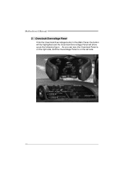
Bios Setup
Page 2
... through the options and settings in the Phoenix-Award™ BIOS Setup program on this motherboard. ACPI Support Phoenix-Award ACPI BIOS support Version 1.0b of Advanced Configuration and Power interface specification (ACPI). P4M900-M7 SE/P4M890-M7 TE BIOS Setup Introduction The purpose of this manual is to describe the settings in BIOS Setup...
... through the options and settings in the Phoenix-Award™ BIOS Setup program on this motherboard. ACPI Support Phoenix-Award ACPI BIOS support Version 1.0b of Advanced Configuration and Power interface specification (ACPI). P4M900-M7 SE/P4M890-M7 TE BIOS Setup Introduction The purpose of this manual is to describe the settings in BIOS Setup...


