
Terminator C3V User Manual
Page 25
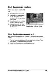
... an expansion card After installing the expansion card, configure it is properly seated in the slot. 4. Install the software drivers for information on BIOS setup. 2. ASUS Terminator 1 C3 barebone system 2-9 Press the card firmly until it by adjusting the software settings. 1. Place the chassis on the system and change the necessary BIOS settings...
... an expansion card After installing the expansion card, configure it is properly seated in the slot. 4. Install the software drivers for information on BIOS setup. 2. ASUS Terminator 1 C3 barebone system 2-9 Press the card firmly until it by adjusting the software settings. 1. Place the chassis on the system and change the necessary BIOS settings...
Terminator C3V User Manual
Page 44
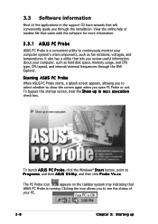
... applications in the support CD have wizards that lets you review useful information about your computer, such as fan rotations, voltages, and temperatures. Starting ASUS PC Probe When ASUS PC Probe starts, a splash screen appears, allowing you to select whether to P r o g r a m s, and then A S U S U t i l i t y, and then ...that came with the software for more information. 3.3.1 ASUS PC Probe ASUS PC Probe is running. To launch A S U S P C P r o b e, click the Windows® S t a r t button, point to show the screen again when you open PC Probe or not. x x. Clicking the icon...
... applications in the support CD have wizards that lets you review useful information about your computer, such as fan rotations, voltages, and temperatures. Starting ASUS PC Probe When ASUS PC Probe starts, a splash screen appears, allowing you to select whether to P r o g r a m s, and then A S U S U t i l i t y, and then ...that came with the software for more information. 3.3.1 ASUS PC Probe ASUS PC Probe is running. To launch A S U S P C P r o b e, click the Windows® S t a r t button, point to show the screen again when you open PC Probe or not. x x. Clicking the icon...
Terminator C3V User Manual
Page 48
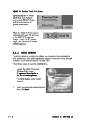
... Probe senses a problem with your PC, portions of the ASUS PC Probe icon change to red, the PC speaker beeps, and the ASUS PC Probe monitor appears. 3.3.2 ASUS Update The ASUS Update is a utility that allows you to open or exit ASUS PC Probe and pause or resume all system monitoring. Select your Windows Start menu...
... Probe senses a problem with your PC, portions of the ASUS PC Probe icon change to red, the PC speaker beeps, and the ASUS PC Probe monitor appears. 3.3.2 ASUS Update The ASUS Update is a utility that allows you to open or exit ASUS PC Probe and pause or resume all system monitoring. Select your Windows Start menu...

Terminator C3V User Manual
Page 59
... Windows® XP Service Pack 1 before using Windows® 2000/XP. 9 . Connect the S/PDIF module cable to this connector, then install the module to a slot opening at the back of the system chassis. 8 . Serial ATA connectors (7-pin SATA1 [black], SATA2 [black]) These connectors are using Serial ATA hard disk drives. The.../Philips Digital Interface (S/PDIF) port(s). The Serial ATA RAID feature (RAID 0/RAID 1) is purchased separately. ® C3V +5V SPDIFOUT GND C3V Digital audio connector SPDIF_OUT ASUS Terminator T1 C3 barebone system 4-9
... Windows® XP Service Pack 1 before using Windows® 2000/XP. 9 . Connect the S/PDIF module cable to this connector, then install the module to a slot opening at the back of the system chassis. 8 . Serial ATA connectors (7-pin SATA1 [black], SATA2 [black]) These connectors are using Serial ATA hard disk drives. The.../Philips Digital Interface (S/PDIF) port(s). The Serial ATA RAID feature (RAID 0/RAID 1) is purchased separately. ® C3V +5V SPDIFOUT GND C3V Digital audio connector SPDIF_OUT ASUS Terminator T1 C3 barebone system 4-9

Terminator C3V User Manual
Page 60
USB 2.0 connectors (10-1 pin USB34, USB56, USB78) These connectors are for the optional TV-out and S-Video out ports. ® C3V J1 C3V TV-out/S-Video out connector 4-10 Chapter 4: Motherboard information These USB connectors comply with USB 2.0 specification that supports up to a slot opening at the back of the system chassis. Connect the USB module cable to any of these connectors, then install the module to 480 Mbps connection speed. ® C3V C3V USB 2.0 connectors 11. TV-out/S-Video out connector (10-1 pin J1) This connector is for USB 2.0 ports. 10.
USB 2.0 connectors (10-1 pin USB34, USB56, USB78) These connectors are for the optional TV-out and S-Video out ports. ® C3V J1 C3V TV-out/S-Video out connector 4-10 Chapter 4: Motherboard information These USB connectors comply with USB 2.0 specification that supports up to a slot opening at the back of the system chassis. Connect the USB module cable to any of these connectors, then install the module to 480 Mbps connection speed. ® C3V C3V USB 2.0 connectors 11. TV-out/S-Video out connector (10-1 pin J1) This connector is for USB 2.0 ports. 10.

Terminator C3V User Manual
Page 61
... install the module to a slot opening at the back of the system chassis. ® C3V C3V IEEE 1394 connectors IE1394_1 IE1394_2 1 TPA0+ GND TPB0+ +12V TPA0GND TPB0+12V GND 1 TPA0+ GND TPB0+ +12V TPA0GND TPB0+12V GND NEVER connect a U S B c a b l e to the IEEE 1394a connector. ASUS Terminator T1 C3 barebone system 4-11 ExtSMI# Ground PWRBIN...
... install the module to a slot opening at the back of the system chassis. ® C3V C3V IEEE 1394 connectors IE1394_1 IE1394_2 1 TPA0+ GND TPB0+ +12V TPA0GND TPB0+12V GND 1 TPA0+ GND TPB0+ +12V TPA0GND TPB0+12V GND NEVER connect a U S B c a b l e to the IEEE 1394a connector. ASUS Terminator T1 C3 barebone system 4-11 ExtSMI# Ground PWRBIN...
