
Terminator C3V User Manual
Page 10
Support CD 4. Power cable and plug 3. x User guide * CD-ROM/CD-RW/DVD-ROM/DVD-RW If any of the items is damaged or missing, contact your ASUS Terminator 1 package for the following items: 1 . System package contents Check your retailer immediately. ASUS Terminator 1 barebone system with: • ASUS C3V motherboard with onboard VIA C3 CPU • Floppy disk drive • Optical drive (optional)* 2.
Support CD 4. Power cable and plug 3. x User guide * CD-ROM/CD-RW/DVD-ROM/DVD-RW If any of the items is damaged or missing, contact your ASUS Terminator 1 package for the following items: 1 . System package contents Check your retailer immediately. ASUS Terminator 1 barebone system with: • ASUS C3V motherboard with onboard VIA C3 CPU • Floppy disk drive • Optical drive (optional)* 2.
Terminator C3V User Manual
Page 12
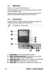
...C3 processor. 1.2 Front panel The ASUS Terminator 1 barebone system is ON. 1-2 Chapter 1: System introduction This covered slot is for a 1.44 MB, 3.5-inch floppy disk. 4 . This drive is for choosing the ASUS Terminator ...v e . E m p t y 5 . 2 5 - Thank you for a second optical drive or other 5.25-inch storage devices. 3 . The ASUS Terminator 1 is an all-in a stylish mini-tower casing, and is powered by the ASUS C3V motherboard that the system is composed of the ASUS C3V motherboard, a power supply, and a floppy disk drive. i n c h d r i v e b a y . The CD-ROM drive is an ...
...C3 processor. 1.2 Front panel The ASUS Terminator 1 barebone system is ON. 1-2 Chapter 1: System introduction This covered slot is for a 1.44 MB, 3.5-inch floppy disk. 4 . This drive is for choosing the ASUS Terminator ...v e . E m p t y 5 . 2 5 - Thank you for a second optical drive or other 5.25-inch storage devices. 3 . The ASUS Terminator 1 is an all-in a stylish mini-tower casing, and is powered by the ASUS C3V motherboard that the system is composed of the ASUS C3V motherboard, a power supply, and a floppy disk drive. i n c h d r i v e b a y . The CD-ROM drive is an ...
Terminator C3V User Manual
Page 52
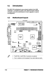
PRI_IDE SEC_IDE 22.4cm (8.82in) 4-2 Chapter 4: Motherboard information 4.1 Introduction The ASUS C3V motherboard comes already installed in the ASUS Terminator 1 C3 barebone system. This chapter provides technical information about the motherboard for future upgrades or system reconfiguraiton. 4.2 Motherboard layout ATXPWR ...FLOPPY CHA_FAN CPU_FAN DDR DIMM2 (64/72-bit, 184-pin module) DDR DIMM1 (64/72-bit, 184-pin module) ® C3V SB_PWR VIA C3 CPU VIA CLE266 RJ-45 LANLED USB_12 T:Port0 B:Port1 USBPWR12 IE1394_1 J1 VIA VT1622A CR2032 3V Lithium Cell CMOS Power VIA VT6307 ...
PRI_IDE SEC_IDE 22.4cm (8.82in) 4-2 Chapter 4: Motherboard information 4.1 Introduction The ASUS C3V motherboard comes already installed in the ASUS Terminator 1 C3 barebone system. This chapter provides technical information about the motherboard for future upgrades or system reconfiguraiton. 4.2 Motherboard layout ATXPWR ...FLOPPY CHA_FAN CPU_FAN DDR DIMM2 (64/72-bit, 184-pin module) DDR DIMM1 (64/72-bit, 184-pin module) ® C3V SB_PWR VIA C3 CPU VIA CLE266 RJ-45 LANLED USB_12 T:Port0 B:Port1 USBPWR12 IE1394_1 J1 VIA VT1622A CR2032 3V Lithium Cell CMOS Power VIA VT6307 ...

Terminator C3V User Manual
Page 53
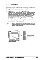
... wake-up (3-pin USBPWR12, USBPWR34, USBPWR56, USBPWR78) Set these jumpers to +5V to wake up the system from S3, S4, and S5 sleep mode. ® C3V C3V USB device wake-up the computer from S3, S4, and S5 sleep mode (no power to additional USB ports. • The motherboard provides 0.5A for... and 1.5A for the internal USB connectors that you want to wake up USBPWR12 2 1 +5V 3 2 +5VSB (Default) USBPWR34 USBPWR56 USBPWR78 12 23 +5V +5VSB (Default) ASUS Terminator T1 C3 barebone system 4-3 The USBPWR12 jumper is for all devices requiring +5VSB power.
... wake-up (3-pin USBPWR12, USBPWR34, USBPWR56, USBPWR78) Set these jumpers to +5V to wake up the system from S3, S4, and S5 sleep mode. ® C3V C3V USB device wake-up the computer from S3, S4, and S5 sleep mode (no power to additional USB ports. • The motherboard provides 0.5A for... and 1.5A for the internal USB connectors that you want to wake up USBPWR12 2 1 +5V 3 2 +5VSB (Default) USBPWR34 USBPWR56 USBPWR78 12 23 +5V +5VSB (Default) ASUS Terminator T1 C3 barebone system 4-3 The USBPWR12 jumper is for all devices requiring +5VSB power.
Terminator C3V User Manual
Page 55
...-1 pin PRI_IDE, SEC_IDE) These connectors are for Ultra DMA 133/100/66 IDE devices. ® C3V C3V IDE connectors PRI_IDE SEC_IDE NOTE: Orient the red markings (usually zigzag) on the IDE ribbon cable to PIN 1. PIN 1 ASUS Terminator T1 C3 barebone system 4-5 See page 1-4 for the jumper settings. • Pin 20 on the Ultra DMA...
...-1 pin PRI_IDE, SEC_IDE) These connectors are for Ultra DMA 133/100/66 IDE devices. ® C3V C3V IDE connectors PRI_IDE SEC_IDE NOTE: Orient the red markings (usually zigzag) on the IDE ribbon cable to PIN 1. PIN 1 ASUS Terminator T1 C3 barebone system 4-5 See page 1-4 for the jumper settings. • Pin 20 on the Ultra DMA...
Terminator C3V User Manual
Page 57
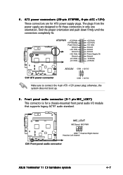
...audio I/O module that supports legacy AC'97 audio standard. ® C3V MIC_LOUT MIC Signal MIC PWR 1 GND Head set Right channel Head set Left channel C3V Front panel audio connector ASUS Terminator T1 C3 barebone system 4-7 Find the proper orientation and push down firmly until the... connectors completely fit. ® C3V ATXPWR +12.0Volts +5V Standby Power Good Ground +5.0 Volts Ground ...
...audio I/O module that supports legacy AC'97 audio standard. ® C3V MIC_LOUT MIC Signal MIC PWR 1 GND Head set Right channel Head set Left channel C3V Front panel audio connector ASUS Terminator T1 C3 barebone system 4-7 Find the proper orientation and push down firmly until the... connectors completely fit. ® C3V ATXPWR +12.0Volts +5V Standby Power Good Ground +5.0 Volts Ground ...

Terminator C3V User Manual
Page 59
...back of the system chassis. The Serial ATA RAID feature (RAID 0/RAID 1) is purchased separately. ® C3V +5V SPDIFOUT GND C3V Digital audio connector SPDIF_OUT ASUS Terminator T1 C3 barebone system 4-9 The S/PDIF module is available only if you are for the Serial ATA signal cables for...(4-1 pin SPDIF_OUT) This connector is for Serial ATA hard disk drives. ® C3V SATA2 GND RSATA_TXP2 RSATA_TXN2 GND RSATA_RXP2 RSATA_RXN2 GND GND RSATA_TXP1 RSATA_TXN1 GND RSATA_RXP1 RSATA_RXN1 GND SATA1 C3V SATA connectors You must install Windows® 2000 Service Pack 4 or the Windows&#...
...back of the system chassis. The Serial ATA RAID feature (RAID 0/RAID 1) is purchased separately. ® C3V +5V SPDIFOUT GND C3V Digital audio connector SPDIF_OUT ASUS Terminator T1 C3 barebone system 4-9 The S/PDIF module is available only if you are for the Serial ATA signal cables for...(4-1 pin SPDIF_OUT) This connector is for Serial ATA hard disk drives. ® C3V SATA2 GND RSATA_TXP2 RSATA_TXN2 GND RSATA_RXP2 RSATA_RXN2 GND GND RSATA_TXP1 RSATA_TXN1 GND RSATA_RXP1 RSATA_RXN1 GND SATA1 C3V SATA connectors You must install Windows® 2000 Service Pack 4 or the Windows&#...

Terminator C3V User Manual
Page 61
... PANEL) This connector supports several chassis-mounted functions. ® C3V PLED SPEAKER +5 V PLED +5V Ground Ground Speaker IDE_LED+ IDE_LED- ASUS Terminator T1 C3 barebone system 4-11 ExtSMI# Ground PWRBIN Ground Reset Ground C3V System panel connectors RESET IDELED PWRBTN SMI * Requires an ATX ...Connect the IEEE 1394a module cable to this connector, then install the module to a slot opening at the back of the system chassis. ® C3V C3V IEEE 1394 connectors IE1394_1 IE1394_2 1 TPA0+ GND TPB0+ +12V TPA0GND TPB0+12V GND 1 TPA0+ GND TPB0+ +12V TPA0GND TPB0+12V GND ...
... PANEL) This connector supports several chassis-mounted functions. ® C3V PLED SPEAKER +5 V PLED +5V Ground Ground Speaker IDE_LED+ IDE_LED- ASUS Terminator T1 C3 barebone system 4-11 ExtSMI# Ground PWRBIN Ground Reset Ground C3V System panel connectors RESET IDELED PWRBTN SMI * Requires an ATX ...Connect the IEEE 1394a module cable to this connector, then install the module to a slot opening at the back of the system chassis. ® C3V C3V IEEE 1394 connectors IE1394_1 IE1394_2 1 TPA0+ GND TPB0+ +12V TPA0GND TPB0+12V GND 1 TPA0+ GND TPB0+ +12V TPA0GND TPB0+12V GND ...

Terminator C3V User Manual
Page 65
..., then select F o r m a t. Insert the disk that contains the new BIOS file into the floppy disk drive. b. ASUS Terminator 1 C3 barebone system 5-3 Download the latest BIOS file from the ASUS website (www.asus.com). W i n d o w s® X P e n v i r o n m e n t a. Rename the file to C3V.BIN and save it to the bootable floppy disk. 5.1.2 Updating the BIOS using the AwardBIOS Flash Utility...
..., then select F o r m a t. Insert the disk that contains the new BIOS file into the floppy disk drive. b. ASUS Terminator 1 C3 barebone system 5-3 Download the latest BIOS file from the ASUS website (www.asus.com). W i n d o w s® X P e n v i r o n m e n t a. Rename the file to C3V.BIN and save it to the bootable floppy disk. 5.1.2 Updating the BIOS using the AwardBIOS Flash Utility...
Terminator C3V User Manual
Page 67
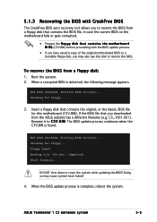
... a corrupted BIOS is complete, reboot the system. Rename it to C 3 V . To recover the BIOS from a floppy disk: 1. B I O S (C3V.BIN) before proceeding with CrashFree BIOS The CrashFree BIOS auto recovery tool allows you to restore the BIOS from a floppy disk that you may cause...is found ! DO NOT shut down or reset the system while updating the BIOS! Doing so may also use this motherboard (C3V.BIN). Starting BIOS recovery... ASUS Terminator 1 C3 barebone system 5-5 Start flashing... 5.1.3 Recovering the BIOS with the BIOS update process. • If you have saved a ...
... a corrupted BIOS is complete, reboot the system. Rename it to C 3 V . To recover the BIOS from a floppy disk: 1. B I O S (C3V.BIN) before proceeding with CrashFree BIOS The CrashFree BIOS auto recovery tool allows you to restore the BIOS from a floppy disk that you may cause...is found ! DO NOT shut down or reset the system while updating the BIOS! Doing so may also use this motherboard (C3V.BIN). Starting BIOS recovery... ASUS Terminator 1 C3 barebone system 5-5 Start flashing... 5.1.3 Recovering the BIOS with the BIOS update process. • If you have saved a ...