
Terminator A7VT400 User''s Manual for English
Page 4
... 2.14 Connecting external devices 2-23 Power supply specifications 2-24 2.14.1 Input Characteristics 2-24 2.14.2 Output Characteristics 2-24 2.14.3 Over-Voltage Protection (OVP 2-24 Chapter 3: Starting up 3.1 Installing an operating system 3-2 3.2 Support CD information 3-2 3.2.1 Running the support CD 3-2 3.2.2 Utilities menu 3-3 3.2.3 ASUS Contact information 3-4 3.2.4 Other information 3-5 3.3 Software information 3-7 3.3.1 ASUS PC Probe 3-7 3.3.2 ASUS Update 3-11 Chapter 4: Motherboard info...
... 2.14 Connecting external devices 2-23 Power supply specifications 2-24 2.14.1 Input Characteristics 2-24 2.14.2 Output Characteristics 2-24 2.14.3 Over-Voltage Protection (OVP 2-24 Chapter 3: Starting up 3.1 Installing an operating system 3-2 3.2 Support CD information 3-2 3.2.1 Running the support CD 3-2 3.2.2 Utilities menu 3-3 3.2.3 ASUS Contact information 3-4 3.2.4 Other information 3-5 3.3 Software information 3-7 3.3.1 ASUS PC Probe 3-7 3.3.2 ASUS Update 3-11 Chapter 4: Motherboard info...

Terminator A7VT400 User''s Manual for English
Page 7
... wet. Entsorgung gebrauchter Batterien nach Angaben des Herstellers. Safety information Electrical safety • To prevent electrical shock hazard, disconnect the power cable from the electrical outlet before relocating the system. • When adding or removing devices to or from connectors, slots, ... safety • Before installing devices into the system, carefully read all cables are correctly connected and the power cables are connected. • If the power supply is incorrectly replaced. Do not place the product in any damage, contact your retailer. Contact a qualified ...
... wet. Entsorgung gebrauchter Batterien nach Angaben des Herstellers. Safety information Electrical safety • To prevent electrical shock hazard, disconnect the power cable from the electrical outlet before relocating the system. • When adding or removing devices to or from connectors, slots, ... safety • Before installing devices into the system, carefully read all cables are correctly connected and the power cables are connected. • If the power supply is incorrectly replaced. Do not place the product in any damage, contact your retailer. Contact a qualified ...
Terminator A7VT400 User''s Manual for English
Page 10
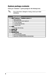
...Terminator 1 system package for the following items. If any of the items is damaged or missing, contact your retailer immediately. Support CD 4 . Optional items • 1 x Floppy disk drive • CPU fan and heatsink assembly • Optical drive (CD-ROM/CD-RW/DVD-ROM/DVD-RW) x User guide 5 . A S U S T e r m i n a t o r 1 b a r e b o n e s y s t e m with • ASUS... motherboard • 165 W PFC/non-PFC power supply unit • 2 x 5.25" drive bays • 1 x 3.5" hard disk drive bay • 4 x USB 2.0 ports 2. Cable • ...
...Terminator 1 system package for the following items. If any of the items is damaged or missing, contact your retailer immediately. Support CD 4 . Optional items • 1 x Floppy disk drive • CPU fan and heatsink assembly • Optical drive (CD-ROM/CD-RW/DVD-ROM/DVD-RW) x User guide 5 . A S U S T e r m i n a t o r 1 b a r e b o n e s y s t e m with • ASUS... motherboard • 165 W PFC/non-PFC power supply unit • 2 x 5.25" drive bays • 1 x 3.5" hard disk drive bay • 4 x USB 2.0 ports 2. Cable • ...
Terminator A7VT400 User''s Manual for English
Page 12
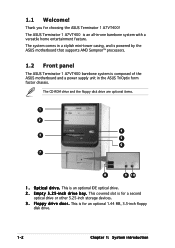
... p p y d r i v e d o o r . This covered slot is composed of the ASUS motherboard and a power supply unit in the ASUS TriOptix form factor chassis. The system comes in -one barebone system with a versatile home entertainment feature. The ASUS Terminator 1 A7VT400 is an optional IDE optical drive. 2 . The CD-ROM drive and the floppy disk drive are optional items... all-in a stylish mini-tower casing, and is powered by the ASUS motherboard that supports AMD Sempron™ processors. 1.2 Front panel The ASUS Terminator 1 A7VT400 barebone system is for a second optical drive or other...
... p p y d r i v e d o o r . This covered slot is composed of the ASUS motherboard and a power supply unit in the ASUS TriOptix form factor chassis. The system comes in -one barebone system with a versatile home entertainment feature. The ASUS Terminator 1 A7VT400 is an optional IDE optical drive. 2 . The CD-ROM drive and the floppy disk drive are optional items... all-in a stylish mini-tower casing, and is powered by the ASUS motherboard that supports AMD Sempron™ processors. 1.2 Front panel The ASUS Terminator 1 A7VT400 barebone system is for a second optical drive or other...
Terminator A7VT400 User''s Manual for English
Page 15
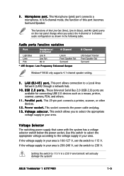
... V, set the switch to the voltage supply in your area. ASUS Terminator 1 A7VT400 1-5 8 . This port allows connection to 230 V. If the voltage supply in the following table. In 4/6-channel ... . M i c r o p h o n e p o r t . This 25-pin port connects a printer, scanner, or other devices. 1 2 . This socket connects the power cable and plug. 1 3 . Voltage Selector The switching power supply that came with the system has a voltage selector switch below the power socket. This Microphone (pink) port connects a microphone. Audio ports function variation Port Light Blue Lime Pink...
... V, set the switch to the voltage supply in your area. ASUS Terminator 1 A7VT400 1-5 8 . This port allows connection to 230 V. If the voltage supply in the following table. In 4/6-channel ... . M i c r o p h o n e p o r t . This 25-pin port connects a printer, scanner, or other devices. 1 2 . This socket connects the power cable and plug. 1 3 . Voltage Selector The switching power supply that came with the system has a voltage selector switch below the power socket. This Microphone (pink) port connects a microphone. Audio ports function variation Port Light Blue Lime Pink...

Terminator A7VT400 User''s Manual for English
Page 16
.../MIDI/COM1 extension module 2. Motherboard 3. Two 5.25" drive bays (Optional CD-ROM) 4. 3.5" HDD drive bay 5. 3.5" floppy drive bay (Optional floppy disk drive) 6. PFC/Non-PFC power supply 7. The standard components already installed in the system and the locations of the system when you remove the cover and flip out the drive frame...
.../MIDI/COM1 extension module 2. Motherboard 3. Two 5.25" drive bays (Optional CD-ROM) 4. 3.5" HDD drive bay 5. 3.5" floppy drive bay (Optional floppy disk drive) 6. PFC/Non-PFC power supply 7. The standard components already installed in the system and the locations of the system when you remove the cover and flip out the drive frame...
Terminator A7VT400 User''s Manual for English
Page 18
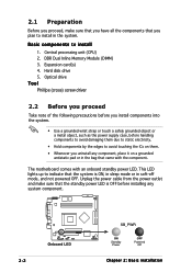
...you install components into the system. • Use a grounded wrist strap or touch a safely grounded object or a metal object, such as the power supply case, before installing any component, place it on them due to static electricity. • Hold components by the edges to install 1. 2.1 Preparation ...is ON, in sleep mode or in the bag that came with an onboard standby power LED. The motherboard comes with the component. Central processing unit (CPU) 2. Unplug the power cable from the power outlet and make sure that you have all the components that you uninstall any system ...
...you install components into the system. • Use a grounded wrist strap or touch a safely grounded object or a metal object, such as the power supply case, before installing any component, place it on them due to static electricity. • Hold components by the edges to install 1. 2.1 Preparation ...is ON, in sleep mode or in the bag that came with an onboard standby power LED. The motherboard comes with the component. Central processing unit (CPU) 2. Unplug the power cable from the power outlet and make sure that you have all the components that you uninstall any system ...

Terminator A7VT400 User''s Manual for English
Page 32
Connect a power cable from the power supply to the black 4-pin connector labeled CD on the IDE interface. 7. Secondary IDE connector (SEC_IDE) CD-ROM connector (CD) 2-16 Chapter 2: Basic installation Connect one end of the IDE ribbon cable to the IDE interface at the back of the audio cable to the power connector at the... CD-ROM audio cable CD-ROM audio cable to the IDE ribbon cable 4-pin connector at the back of the IDE ribbon cable to Pin 1 Power cable (P1) 8.
Connect a power cable from the power supply to the black 4-pin connector labeled CD on the IDE interface. 7. Secondary IDE connector (SEC_IDE) CD-ROM connector (CD) 2-16 Chapter 2: Basic installation Connect one end of the IDE ribbon cable to the IDE interface at the back of the audio cable to the power connector at the... CD-ROM audio cable CD-ROM audio cable to the IDE ribbon cable 4-pin connector at the back of the IDE ribbon cable to Pin 1 Power cable (P1) 8.

Terminator A7VT400 User''s Manual for English
Page 34
5. Red stripe to the primary IDE connector (blue connector labeled PRI_IDE) on the motherboard. Connect one end of the IDE hard disk ribbon cable to the power connector at the back of the HDD. Primary IDE connector (PRI_IDE) 2-18 Chapter 2: Basic installation Connect a power cable from the power supply to the IDE interface at the back of the HDD, matching the red stripe on the IDE interface. Use the cable with Pin 1 on the cable with the white connector labeled P3. 6. Connect the other end of the IDE ribbon cable to Pin 1 IDE ribbon cable Power cable (P3) 7.
5. Red stripe to the primary IDE connector (blue connector labeled PRI_IDE) on the motherboard. Connect one end of the IDE hard disk ribbon cable to the power connector at the back of the HDD. Primary IDE connector (PRI_IDE) 2-18 Chapter 2: Basic installation Connect a power cable from the power supply to the IDE interface at the back of the HDD, matching the red stripe on the IDE interface. Use the cable with Pin 1 on the cable with the white connector labeled P3. 6. Connect the other end of the IDE ribbon cable to Pin 1 IDE ribbon cable Power cable (P3) 7.
Terminator A7VT400 User''s Manual for English
Page 35
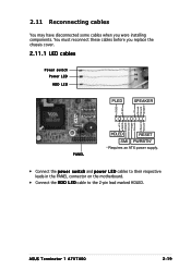
... Ground Reset Ground PANEL HDLED RESET SMI PWRBTN* * Requires an ATX power supply. • Connect the power switch and power LED cables to their respective leads in the PANEL connector on the motherboard. • Connect the H D D L E D cable to the 2-pin lead marked HDLED. ASUS Terminator 1 A7VT400 2-19 You must reconnect these cables before you were installing components.
... Ground Reset Ground PANEL HDLED RESET SMI PWRBTN* * Requires an ATX power supply. • Connect the power switch and power LED cables to their respective leads in the PANEL connector on the motherboard. • Connect the H D D L E D cable to the 2-pin lead marked HDLED. ASUS Terminator 1 A7VT400 2-19 You must reconnect these cables before you were installing components.

Terminator A7VT400 User''s Manual for English
Page 40
... A Regulation Min Max -5% +5% -5% +5% -10% +10% -5% +5% -5% +5% Ripple Max 50mVp-p 120mVp-p 120mVp-p 50mVp-p 50mVp-p 2.14.3 Over-Voltage Protection (OVP) Output Voltage +5 V +12 V +3.3 V Maximum Voltage 6.5 V 15.6 V 4.3 V The power supply will shut down or automatically recover when the fault condition is removed. 2-24 Chapter 2: Basic installation at 115 Vac, full load cold start at 230... Vac, maximum load 90 A max. By shorting +5VSB, the power supply can latch down and latch off for shorting +5V, +12V, -12V, or +3.3V. at 25°C 70% min....
... A Regulation Min Max -5% +5% -5% +5% -10% +10% -5% +5% -5% +5% Ripple Max 50mVp-p 120mVp-p 120mVp-p 50mVp-p 50mVp-p 2.14.3 Over-Voltage Protection (OVP) Output Voltage +5 V +12 V +3.3 V Maximum Voltage 6.5 V 15.6 V 4.3 V The power supply will shut down or automatically recover when the fault condition is removed. 2-24 Chapter 2: Basic installation at 115 Vac, full load cold start at 230... Vac, maximum load 90 A max. By shorting +5VSB, the power supply can latch down and latch off for shorting +5V, +12V, -12V, or +3.3V. at 25°C 70% min....
Terminator A7VT400 User''s Manual for English
Page 55
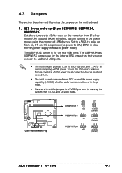
...the USB device wake-up 1 2 USBPWR12 +5V 12 USBPWR34 +5V 12 USBPWR56 +5V 2 3 +5VSB (Default) 23 +5VSB (Default) 23 +5VSB (Default) ASUS Terminator T1 A7VT400 4-3 The USBPWR34 and USBPWR56 jumpers are for the internal USB connectors that you can connect to wake up the system from S3, S4, and S5 ...sleep mode. ® USB device wake-up feature, the total +5VSB power for all connected devices must not exceed 1.5A. • The total current consumed must NOT exceed the power supply capability (+5VSB), whether under normal condition or in sleep mode. • Make sure to set ...
...the USB device wake-up 1 2 USBPWR12 +5V 12 USBPWR34 +5V 12 USBPWR56 +5V 2 3 +5VSB (Default) 23 +5VSB (Default) 23 +5VSB (Default) ASUS Terminator T1 A7VT400 4-3 The USBPWR34 and USBPWR56 jumpers are for the internal USB connectors that you can connect to wake up the system from S3, S4, and S5 ...sleep mode. ® USB device wake-up feature, the total +5VSB power for all connected devices must not exceed 1.5A. • The total current consumed must NOT exceed the power supply capability (+5VSB), whether under normal condition or in sleep mode. • Make sure to set ...

Terminator A7VT400 User''s Manual for English
Page 60
... Volts Ground +5.0 Volts Ground +3.3 Volts +3.3 Volts +5.0 Volts +5.0 Volts -5.0 Volts Ground Ground Ground Power Supply On Ground -12.0Volts +3.3Volts ATX12V COM +12V DC ® ATX power connector COM +12V DC Make sure to fit these connectors in only one orientation. Find the proper ...audio connector (5-1 pin MIC_LOUT) This connector is for ATX power supply plugs. ATX power connectors (20-pin ATXPWR, 4-pin ATX +12V) These connectors are designed to connect the 4-pin ATX +12V power plug; The plugs from the power supply are for a chassis-mounted front panel audio I/O module that...
... Volts Ground +5.0 Volts Ground +3.3 Volts +3.3 Volts +5.0 Volts +5.0 Volts -5.0 Volts Ground Ground Ground Power Supply On Ground -12.0Volts +3.3Volts ATX12V COM +12V DC ® ATX power connector COM +12V DC Make sure to fit these connectors in only one orientation. Find the proper ...audio connector (5-1 pin MIC_LOUT) This connector is for ATX power supply plugs. ATX power connectors (20-pin ATXPWR, 4-pin ATX +12V) These connectors are designed to connect the 4-pin ATX +12V power plug; The plugs from the power supply are for a chassis-mounted front panel audio I/O module that...

Terminator A7VT400 User''s Manual for English
Page 62
... PWR Ground Reset Ground ® System panel connector HDLED RESET SMI PWRBTN* * Requires an ATX power supply. 4-10 Chapter 4: Motherboard information USBP3+ GND 1 5 1 5 USB34 USB56 6 10 6 10 USB Power USBP3- USBP2+ GND NC ® USB connectors USB Power USBP3- System panel connector (20-pin PANEL) This connector supports several chassis-mounted functions. These USB...
... PWR Ground Reset Ground ® System panel connector HDLED RESET SMI PWRBTN* * Requires an ATX power supply. 4-10 Chapter 4: Motherboard information USBP3+ GND 1 5 1 5 USB34 USB56 6 10 6 10 USB Power USBP3- USBP2+ GND NC ® USB connectors USB Power USBP3- System panel connector (20-pin PANEL) This connector supports several chassis-mounted functions. These USB...
Terminator A7VT400 User''s Manual for English
Page 87
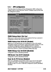
... you to wake up menu with the configuration options. This feature requires an ATX power supply that provides at least 1A on the system. 5.5.1 APM configuration This menu shows the Advanced Power Management (APM) configuration settings. Select an item then press to turn on the...:ss) Video Off Option PWR Button Off] [Instant-Off] [Power Off] Item Specific Help PS2KB Wakeup Select [Hot Key] Allows you to turn on the +5VSB lead. Configuration options: [Disabled] [Enabled] ASUS Terminator 1 A7VT400 5-23 APM Configuration Select Menu PS2KB Wakeup Select PS2KB Wakeup Password ...
... you to wake up menu with the configuration options. This feature requires an ATX power supply that provides at least 1A on the system. 5.5.1 APM configuration This menu shows the Advanced Power Management (APM) configuration settings. Select an item then press to turn on the...:ss) Video Off Option PWR Button Off] [Instant-Off] [Power Off] Item Specific Help PS2KB Wakeup Select [Hot Key] Allows you to turn on the +5VSB lead. Configuration options: [Disabled] [Enabled] ASUS Terminator 1 A7VT400 5-23 APM Configuration Select Menu PS2KB Wakeup Select PS2KB Wakeup Password ...

Terminator A7VT400 User''s Manual for English
Page 90
...] [45oC/113oF] [50oC/122oF] [55oC/131oF] [60oC/140oF] [65oC/149oF] [70oC/158oF] [75oC/167oF] Power Temperature [xxxoC/xxxoF ] CPU Temperature [xxxoC/xxxoF ] The onboard hardware monitor automatically detects and displays the power supply and CPU temperatures in rotations per minute (RPM). 5-26 Chapter 5: BIOS information Q-Fan Function [Disabled] This item...high. 5.5.2 Hardware monitor This menu shows the hardware monitor configuration settings. Select an item then press to enable or disable the ASUS Q-Fan feature that smartly adjusts the CPU fan speed for more efficient system operation.
...] [45oC/113oF] [50oC/122oF] [55oC/131oF] [60oC/140oF] [65oC/149oF] [70oC/158oF] [75oC/167oF] Power Temperature [xxxoC/xxxoF ] CPU Temperature [xxxoC/xxxoF ] The onboard hardware monitor automatically detects and displays the power supply and CPU temperatures in rotations per minute (RPM). 5-26 Chapter 5: BIOS information Q-Fan Function [Disabled] This item...high. 5.5.2 Hardware monitor This menu shows the hardware monitor configuration settings. Select an item then press to enable or disable the ASUS Q-Fan feature that smartly adjusts the CPU fan speed for more efficient system operation.


