
Terminator A7VT400 User''s Manual for English
Page 4
... 3: Starting up 3.1 Installing an operating system 3-2 3.2 Support CD information 3-2 3.2.1 Running the support CD 3-2 3.2.2 Utilities menu 3-3 3.2.3 ASUS Contact information 3-4 3.2.4 Other information 3-5 3.3 Software information 3-7 3.3.1 ASUS PC Probe 3-7 3.3.2 ASUS Update 3-11 Chapter 4: Motherboard info 4.1 Introduction 4-2 4.2 Motherboard layout 4-2 4.3 Jumpers 4-3 4.4 Connectors 4-6 Chapter 5: BIOS information 5.1 Managing and updating your BIOS 5-2 5.1.1 Creating a bootable floppy disk 5-2 5.1.2 Updating the BIOS using the AwardBIOS Flash Utility 5-3 5.1.3 Recovering...
... 3: Starting up 3.1 Installing an operating system 3-2 3.2 Support CD information 3-2 3.2.1 Running the support CD 3-2 3.2.2 Utilities menu 3-3 3.2.3 ASUS Contact information 3-4 3.2.4 Other information 3-5 3.3 Software information 3-7 3.3.1 ASUS PC Probe 3-7 3.3.2 ASUS Update 3-11 Chapter 4: Motherboard info 4.1 Introduction 4-2 4.2 Motherboard layout 4-2 4.3 Jumpers 4-3 4.4 Connectors 4-6 Chapter 5: BIOS information 5.1 Managing and updating your BIOS 5-2 5.1.1 Creating a bootable floppy disk 5-2 5.1.2 Updating the BIOS using the AwardBIOS Flash Utility 5-3 5.1.3 Recovering...

Terminator A7VT400 User''s Manual for English
Page 6
... to Part 15 of the monitor to the graphics card is connected. • Consult the dealer or an experienced radio/TV technician for connection of the FCC Rules. Canadian Department of Communications. The use of shielded cables for help. vi This equipment has been tested and found to comply with the limits for compliance could void the user's authority to operate...
... to Part 15 of the monitor to the graphics card is connected. • Consult the dealer or an experienced radio/TV technician for connection of the FCC Rules. Canadian Department of Communications. The use of shielded cables for help. vi This equipment has been tested and found to comply with the limits for compliance could void the user's authority to operate...
Terminator A7VT400 User''s Manual for English
Page 10
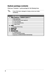
... Terminator 1 system package for the following items. If any of the items is damaged or missing, contact your retailer immediately. Support CD 4 . User guide 5 . A S U S T e r m i n a t o r 1 b a r e b o n e s y s t e m with • ASUS motherboard • 165 W PFC/non-PFC power supply unit • 2 x 5.25" drive bays • 1 x 3.5" hard disk drive bay • 4 x USB 2.0 ports 2. Cable • AC power cable and plug 3 . Item description 1 . Optional items • 1 x Floppy disk drive • CPU fan and heatsink assembly • Optical drive (CD-ROM/CD-RW/DVD-ROM/DVD...
... Terminator 1 system package for the following items. If any of the items is damaged or missing, contact your retailer immediately. Support CD 4 . User guide 5 . A S U S T e r m i n a t o r 1 b a r e b o n e s y s t e m with • ASUS motherboard • 165 W PFC/non-PFC power supply unit • 2 x 5.25" drive bays • 1 x 3.5" hard disk drive bay • 4 x USB 2.0 ports 2. Cable • AC power cable and plug 3 . Item description 1 . Optional items • 1 x Floppy disk drive • CPU fan and heatsink assembly • Optical drive (CD-ROM/CD-RW/DVD-ROM/DVD...
Terminator A7VT400 User''s Manual for English
Page 12
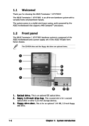
... CD-ROM drive and the floppy disk drive are optional items. 1 2 4 3 5 6 7 8 9 10 1 . This is an optional IDE optical drive. 2 . Thank you for an optional 1.44 MB, 3.5-inch floppy disk drive. 1-2 Chapter 1: System introduction E m p t y 5 . 2 5 - The ASUS Terminator 1 A7VT400 is an all-in a stylish mini-tower casing, and is powered by the ASUS motherboard that supports AMD Sempron™ processors. 1.2 Front panel The ASUS Terminator 1 A7VT400 barebone system is for a second optical drive or other 5.25-inch storage devices...
... CD-ROM drive and the floppy disk drive are optional items. 1 2 4 3 5 6 7 8 9 10 1 . This is an optional IDE optical drive. 2 . Thank you for an optional 1.44 MB, 3.5-inch floppy disk drive. 1-2 Chapter 1: System introduction E m p t y 5 . 2 5 - The ASUS Terminator 1 A7VT400 is an all-in a stylish mini-tower casing, and is powered by the ASUS motherboard that supports AMD Sempron™ processors. 1.2 Front panel The ASUS Terminator 1 A7VT400 barebone system is for a second optical drive or other 5.25-inch storage devices...
Terminator A7VT400 User''s Manual for English
Page 14
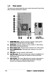
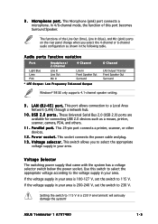
...L i n e O u t p o r t . This Line In (light blue) port connects a tape player or other devices that allow convenient connection of this port becomes Low Frequency Enhanced Output/Center. 1-4 Chapter 1: System introduction S e r i a l p o r t . P S / 2 m o u s e p o r t . This port connects a VGA monitor. 6 . This port connects a joystick or game pad for playing games, and MIDI devices for a PS/2 mouse. 4 . This purple 6-pin connector is for audio editing. 2 . 1.3 Rear panel The system rear panel includes the power socket and several I n p o r t . G A M E / M I D I p o r t .
...L i n e O u t p o r t . This Line In (light blue) port connects a tape player or other devices that allow convenient connection of this port becomes Low Frequency Enhanced Output/Center. 1-4 Chapter 1: System introduction S e r i a l p o r t . P S / 2 m o u s e p o r t . This port connects a VGA monitor. 6 . This port connects a joystick or game pad for playing games, and MIDI devices for a PS/2 mouse. 4 . This purple 6-pin connector is for audio editing. 2 . 1.3 Rear panel The system rear panel includes the power socket and several I n p o r t . G A M E / M I D I p o r t .
Terminator A7VT400 User''s Manual for English
Page 15
... SE only supports 4.1-channel speaker setting. 9 . These Universal Serial Bus 2.0 (USB 2.0) ports are available for connecting USB 2.0 devices such as shown in your area is 100-127 V, set the switch to 115 V. This socket connects the power cable and plug. 1 3 . If the voltage supply in the following table. U S B 2 . 0 p o r t s . If the voltage supply in a 230 V environment will seriously damage the system! ASUS Terminator 1 A7VT400 1-5 This Microphone (pink) port connects a microphone. In 4/6-channel mode, the...
... SE only supports 4.1-channel speaker setting. 9 . These Universal Serial Bus 2.0 (USB 2.0) ports are available for connecting USB 2.0 devices such as shown in your area is 100-127 V, set the switch to 115 V. This socket connects the power cable and plug. 1 3 . If the voltage supply in the following table. U S B 2 . 0 p o r t s . If the voltage supply in a 230 V environment will seriously damage the system! ASUS Terminator 1 A7VT400 1-5 This Microphone (pink) port connects a microphone. In 4/6-channel mode, the...
Terminator A7VT400 User''s Manual for English
Page 18
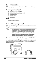
...; Use a grounded wrist strap or touch a safely grounded object or a metal object, such as the power supply case, before installing any component, place it on them due to static electricity. • Hold components by the edges to install 1. This LED lights up to install in the system. DDR Dual Inline Memory Module (DIMM) 3. 2.1 Preparation Before you proceed, make sure that the standby power LED...
...; Use a grounded wrist strap or touch a safely grounded object or a metal object, such as the power supply case, before installing any component, place it on them due to static electricity. • Hold components by the edges to install 1. This LED lights up to install in the system. DDR Dual Inline Memory Module (DIMM) 3. 2.1 Preparation Before you proceed, make sure that the standby power LED...
Terminator A7VT400 User''s Manual for English
Page 29
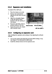
... the software settings. 1. Metal bracket PCI slot (PCI1) 5. ASUS Terminator 1 A7VT400 2-13 AGP slot (AGP1) 2.8.3 Configuring an expansion card After installing the expansion card, configure it is properly seated on BIOS setup. 2. Turn on the chassis. 4. Install the software drivers for information on the slot. Remove the metal bracket opposite the slot that you wish to the chassis with a bracket screw. See Chapter 5 for the expansion card. Secure the card to use. 3. Align the card golden...
... the software settings. 1. Metal bracket PCI slot (PCI1) 5. ASUS Terminator 1 A7VT400 2-13 AGP slot (AGP1) 2.8.3 Configuring an expansion card After installing the expansion card, configure it is properly seated on BIOS setup. 2. Turn on the chassis. 4. Install the software drivers for information on the slot. Remove the metal bracket opposite the slot that you wish to the chassis with a bracket screw. See Chapter 5 for the expansion card. Secure the card to use. 3. Align the card golden...
Terminator A7VT400 User''s Manual for English
Page 42
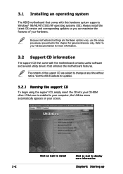
3.1 Installing an operating system The ASUS motherboard that enhance the motherboard features. Because motherboard settings and hardware options vary, use the setup procedures presented in your computer, the Utilities menu automatically appears on your screen. 3-2 Click an item to install Click an icon to display more information. 3.2 Support CD information The support CD that came with the motherboard contains useful software and several utility drivers that comes with this chapter for updates. 3.2.1 Running the support CD To...
3.1 Installing an operating system The ASUS motherboard that enhance the motherboard features. Because motherboard settings and hardware options vary, use the setup procedures presented in your computer, the Utilities menu automatically appears on your screen. 3-2 Click an item to install Click an icon to display more information. 3.2 Support CD information The support CD that came with the motherboard contains useful software and several utility drivers that comes with this chapter for updates. 3.2.1 Running the support CD To...

Terminator A7VT400 User''s Manual for English
Page 56
.... 4-4 Chapter 4: Motherboard information Re-install the battery. 5. Hold down the key during the boot process and enter BIOS setup to pins 1-2. Remove the battery. 3. The onboard button cell battery powers the RAM data in CMOS. Keep the cap on pins 1-2 for about 5~10 seconds, then move the cap back to clear the Real Time Clock (RTC) RAM in CMOS, which include system setup information such as system passwords. You can clear the CMOS memory of...
.... 4-4 Chapter 4: Motherboard information Re-install the battery. 5. Hold down the key during the boot process and enter BIOS setup to pins 1-2. Remove the battery. 3. The onboard button cell battery powers the RAM data in CMOS. Keep the cap on pins 1-2 for about 5~10 seconds, then move the cap back to clear the Real Time Clock (RTC) RAM in CMOS, which include system setup information such as system passwords. You can clear the CMOS memory of...

Terminator A7VT400 User''s Manual for English
Page 58
... 133/100/66 IDE devices. ® IDE connectors SEC_IDE PRI_IDE NOTE: Orient the red markings (usually zigzag) on the IDE ribbon cable to match the covered hole on the motherboard, a black connector for an Ultra DMA 133/100/66 IDE slave device (optical drive/hard disk drive), and a gray connector for the description of rear panel connectors. 1 . Refer to the hard disk documentation for the jumper settings. • Pin 20 on the...
... 133/100/66 IDE devices. ® IDE connectors SEC_IDE PRI_IDE NOTE: Orient the red markings (usually zigzag) on the IDE ribbon cable to match the covered hole on the motherboard, a black connector for an Ultra DMA 133/100/66 IDE slave device (optical drive/hard disk drive), and a gray connector for the description of rear panel connectors. 1 . Refer to the hard disk documentation for the jumper settings. • Pin 20 on the...
Terminator A7VT400 User''s Manual for English
Page 63
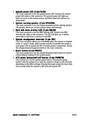
.... • Hard disk drive activity LED (2-pin HDLED) This 2-pin connector is for the HDD Activity LED. The IDE LED lights up when you turn on the BIOS settings. Pressing the power button turns the system on or puts the system in sleep or soft-off button (2-pin PWRBTN) This connector is for the system power button. Attach the chassis-mounted suspend switch to this connector. ASUS Terminator T1 A7VT400 4-11 Connect the HDD Activity LED cable to this 2-pin connector. • Reset button (2-pin RESET) This 2-pin connector is...
.... • Hard disk drive activity LED (2-pin HDLED) This 2-pin connector is for the HDD Activity LED. The IDE LED lights up when you turn on the BIOS settings. Pressing the power button turns the system on or puts the system in sleep or soft-off button (2-pin PWRBTN) This connector is for the system power button. Attach the chassis-mounted suspend switch to this connector. ASUS Terminator T1 A7VT400 4-11 Connect the HDD Activity LED cable to this 2-pin connector. • Reset button (2-pin RESET) This 2-pin connector is...

Terminator A7VT400 User''s Manual for English
Page 72
... reset button on . The Flash ROM on your BIOS." The Setup program is constantly being updated, the following BIOS setup screens and descriptions are installing a motherboard, reconfiguring your computer in the CMOS RAM of your system, or prompted to "Run Setup." This section explains how to use the Setup program, you are for reference purposes only, and may want to enable the security password feature or make it as easy to configure...
... reset button on . The Flash ROM on your BIOS." The Setup program is constantly being updated, the following BIOS setup screens and descriptions are installing a motherboard, reconfiguring your computer in the CMOS RAM of your system, or prompted to "Run Setup." This section explains how to use the Setup program, you are for reference purposes only, and may want to enable the security password feature or make it as easy to configure...

Terminator A7VT400 User''s Manual for English
Page 74
... the fields, use the set default hot key to any menu by simply pressing . If you accidentally make unwanted changes to load the Setup default values. While moving around through the Setup program, note that will not fit in the Item Specific Help window located to field within a menu. This pointer indicates that a right pointer symbol (as you can display a sub-menu from this screen from field...
... the fields, use the set default hot key to any menu by simply pressing . If you accidentally make unwanted changes to load the Setup default values. While moving around through the Setup program, note that will not fit in the Item Specific Help window located to field within a menu. This pointer indicates that a right pointer symbol (as you can display a sub-menu from this screen from field...

Terminator A7VT400 User''s Manual for English
Page 79
... [2T] Select Menu Item Specific Help Set DRAM Frequency. Configuration options: [1T Command] [2T Command] Write Recovery Time [3T] Sets the DRAM write recovery time. Select [Auto by SPD] [Manual] [Safe] DRAM Burst Length [4] Sets the DRAM burst length width. Configuration options: [4] [8] DRAM Command Rate [2T Command] Sets the DRAM command rate . Configuration options: [1T] [2T] ASUS Terminator 1 A7VT400 5-15 DRAM Clock [By SPD] Sets the DRAM frequency. Configuration options: [Auto...
... [2T] Select Menu Item Specific Help Set DRAM Frequency. Configuration options: [1T Command] [2T Command] Write Recovery Time [3T] Sets the DRAM write recovery time. Select [Auto by SPD] [Manual] [Safe] DRAM Burst Length [4] Sets the DRAM burst length width. Configuration options: [4] [8] DRAM Command Rate [2T Command] Sets the DRAM command rate . Configuration options: [1T] [2T] ASUS Terminator 1 A7VT400 5-15 DRAM Clock [By SPD] Sets the DRAM frequency. Configuration options: [Auto...
Terminator A7VT400 User''s Manual for English
Page 83
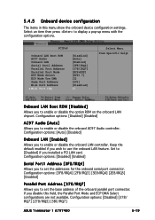
...controller. Configuration options: [Disabled] [378/ IRQ7] [278/IRQ5] [3BC/IRQ7] ASUS Terminator 1 A7VT400 5-19 Keep the default enabled if you to set the base address of the onboard parallel port connector. Configuration options: [Disabled] [Enabled] Serial Port1 Address [3F8/IRQ4] Allows you to enable or disable the onboard AC97 Audio controller. Set to [Disabled] if you to set the addresses for the onboard serial port connector. Configuration options: [Disabled] [Enabled] AC97 Audio [Auto] Allows you installed a PCI LAN card. 5.4.5 Onboard device configuration...
...controller. Configuration options: [Disabled] [378/ IRQ7] [278/IRQ5] [3BC/IRQ7] ASUS Terminator 1 A7VT400 5-19 Keep the default enabled if you to set the base address of the onboard parallel port connector. Configuration options: [Disabled] [Enabled] Serial Port1 Address [3F8/IRQ4] Allows you to enable or disable the onboard AC97 Audio controller. Set to [Disabled] if you to set the addresses for the onboard serial port connector. Configuration options: [Disabled] [Enabled] AC97 Audio [Auto] Allows you installed a PCI LAN card. 5.4.5 Onboard device configuration...
Terminator A7VT400 User''s Manual for English
Page 85
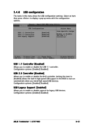
...legacy USB devices. Configuration options: [Enabled] Disabled] USB Legacy Support [Enabled] Allows you to enable or disable the USB 1.1 controller. Select an item then press to enable or disable the EHCI controller. Configuration options: [Enabled] Disabled] USB 2.0 Controller [Enabled] Allows you to display a pop-up menu with the configuration options. Setting this menu show the USB configuration settings. 5.4.6 USB configuration The items in this item to [Enabled] allows the built-in high speed USB support in the BIOS to turn on automatically when you install high speed USB...
...legacy USB devices. Configuration options: [Enabled] Disabled] USB Legacy Support [Enabled] Allows you to enable or disable the USB 1.1 controller. Select an item then press to enable or disable the EHCI controller. Configuration options: [Enabled] Disabled] USB 2.0 Controller [Enabled] Allows you to display a pop-up menu with the configuration options. Setting this menu show the USB configuration settings. 5.4.6 USB configuration The items in this item to [Enabled] allows the built-in high speed USB support in the BIOS to turn on automatically when you install high speed USB...
Terminator A7VT400 User''s Manual for English
Page 87
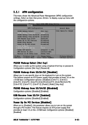
... on the +5VSB lead. Configuration options: [Hot key] [Password] PS2KB Wakeup from S3/S4 [Enabled] Configuration options: [Disabled] [Enabled] Power Up On PCI Devices [Disabled] When set to [Enabled], this parameter allows you to use specific keys on the system. Configuration options: [Disabled] [Enabled] ASUS Terminator 1 A7VT400 5-23 Select an item then press to turn on the keyboard to wake up menu with the configuration options. 5.5.1 APM configuration This menu shows the Advanced Power Management (APM) configuration settings. Configuration options: [Disabled] [Ctrl+F1...
... on the +5VSB lead. Configuration options: [Hot key] [Password] PS2KB Wakeup from S3/S4 [Enabled] Configuration options: [Disabled] [Enabled] Power Up On PCI Devices [Disabled] When set to [Enabled], this parameter allows you to use specific keys on the system. Configuration options: [Disabled] [Enabled] ASUS Terminator 1 A7VT400 5-23 Select an item then press to turn on the keyboard to wake up menu with the configuration options. 5.5.1 APM configuration This menu shows the Advanced Power Management (APM) configuration settings. Configuration options: [Disabled] [Ctrl+F1...

Terminator A7VT400 User''s Manual for English
Page 93
Configuration options: [Removable] [Hard Disk] [CDROM] [Disabled] 5.6.2 Removable drives Removable Drives 1. Bootable Add-in Cards ASUS Terminator 1 A7VT400 Select Menu Item Specific Help Use or arrow to select a device, then press to move it up , or to move it down the list. Press to move it down the list. Floppy Disks Select Menu Item Specific Help Use or arrow to select a device, then press to move it up , or to exit this menu. 5.6.3 Hard disk drives Hard Disk Drives 1. 1st Boot Device [Removable] 2nd Boot Device [Hard Disk] 3rd Boot Device [CDROM] 4th...
Configuration options: [Removable] [Hard Disk] [CDROM] [Disabled] 5.6.2 Removable drives Removable Drives 1. Bootable Add-in Cards ASUS Terminator 1 A7VT400 Select Menu Item Specific Help Use or arrow to select a device, then press to move it up , or to move it down the list. Press to move it down the list. Floppy Disks Select Menu Item Specific Help Use or arrow to select a device, then press to move it up , or to exit this menu. 5.6.3 Hard disk drives Hard Disk Drives 1. 1st Boot Device [Removable] 2nd Boot Device [Hard Disk] 3rd Boot Device [CDROM] 4th...
Terminator A7VT400 User''s Manual for English
Page 97
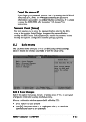
... press , to save your password, you to require the password before exiting the Setup utility. Exit & Save Changes Exit & Discard Changes Load Setup Default Discard Changes Select Menu Item Specific Help This option saves data to CMOS before entering the BIOS Setup. Select [System] to the Exit menu ASUS Terminator 1 A7VT400 5-33 Configuration options: [Setup] [System] 5.7 Exit menu The Exit menu items allow you to load the BIOS setup default settings, save and exit • type [N], then press , or simply...
... press , to save your password, you to require the password before exiting the Setup utility. Exit & Save Changes Exit & Discard Changes Load Setup Default Discard Changes Select Menu Item Specific Help This option saves data to CMOS before entering the BIOS Setup. Select [System] to the Exit menu ASUS Terminator 1 A7VT400 5-33 Configuration options: [Setup] [System] 5.7 Exit menu The Exit menu items allow you to load the BIOS setup default settings, save and exit • type [N], then press , or simply...


