

Terminator A7VT User Manual
Page 2
...of their respective companies, and are used only for identification or explanation and to the owners' benefit, without intent to infringe. 2 ASUS ASSUMES NO RESPONSIBILITY OR LIABILITY FOR ANY ERRORS OR INACCURACIES THAT MAY APPEAR IN THIS MANUAL, INCLUDING THE PRODUCTS AND SOFTWARE DESCRIBED IN ...IT. No part of this manual may or may be registered trademarks or copyrights of ASUSTeK COMPUTER INC. ("ASUS"). SPECIFICATIONS AND INFORMATION CONTAINED IN THIS MANUAL ARE FURNISHED FOR INFORMATIONAL USE ONLY, AND ARE SUBJECT TO CHANGE AT ANY TIME WITHOUT NOTICE, ...
...of their respective companies, and are used only for identification or explanation and to the owners' benefit, without intent to infringe. 2 ASUS ASSUMES NO RESPONSIBILITY OR LIABILITY FOR ANY ERRORS OR INACCURACIES THAT MAY APPEAR IN THIS MANUAL, INCLUDING THE PRODUCTS AND SOFTWARE DESCRIBED IN ...IT. No part of this manual may or may be registered trademarks or copyrights of ASUSTeK COMPUTER INC. ("ASUS"). SPECIFICATIONS AND INFORMATION CONTAINED IN THIS MANUAL ARE FURNISHED FOR INFORMATIONAL USE ONLY, AND ARE SUBJECT TO CHANGE AT ANY TIME WITHOUT NOTICE, ...

Terminator A7VT User Manual
Page 4
...specifications 40 2.14.1 Input Characteristics 40 2.14.3 Over-Voltage Protection (OVP 40 2.14.2 Output Characteristics 40 Chapter 3: Starting up 3.1 Installing an operating system 42 3.2 Support CD information 42 3.2.1 Running the support CD 42 3.2.2 Utilities menu 43 3.2.3 ASUS Contact information 44 3.2.4 Other information 45 3.3 Software information 47 3.3.1 ASUS...Updating the BIOS using the AwardBIOS Flash Utility 67 5.1.3 Recovering the BIOS with CrashFree BIOS ......... 69 5.1.4 ASUS Update 70 5.2 BIOS Setup program 71 5.2.1 BIOS menu bar 72 5.2.2 Legend bar 72 5.3 Main ...
...specifications 40 2.14.1 Input Characteristics 40 2.14.3 Over-Voltage Protection (OVP 40 2.14.2 Output Characteristics 40 Chapter 3: Starting up 3.1 Installing an operating system 42 3.2 Support CD information 42 3.2.1 Running the support CD 42 3.2.2 Utilities menu 43 3.2.3 ASUS Contact information 44 3.2.4 Other information 45 3.3 Software information 47 3.3.1 ASUS...Updating the BIOS using the AwardBIOS Flash Utility 67 5.1.3 Recovering the BIOS with CrashFree BIOS ......... 69 5.1.4 ASUS Update 70 5.2 BIOS Setup program 71 5.2.1 BIOS menu bar 72 5.2.2 Legend bar 72 5.3 Main ...

Terminator A7VT User Manual
Page 14
... function of this port becomes Front Speaker Out. 7. 1.3 Rear panel The system rear panel includes the power socket and several I/O ports that conform with serial specification. 3. This purple 6-pin connector is for audio editing. 2. This Line Out (lime) port connects a headphone or a speaker. In 4/6-channel mode, the function of devices. 1 2 3 4 5 6 7 8 9 10...
... function of this port becomes Front Speaker Out. 7. 1.3 Rear panel The system rear panel includes the power socket and several I/O ports that conform with serial specification. 3. This purple 6-pin connector is for audio editing. 2. This Line Out (lime) port connects a headphone or a speaker. In 4/6-channel mode, the function of devices. 1 2 3 4 5 6 7 8 9 10...

Terminator A7VT User Manual
Page 22
Take note of the marked corner (with a surface mount 462-pin Zero Insertion Force (ZIF) socket designed for the AMD Athlon™ and AMD Duron™ processors. This mark should match a specific corner on the motherboard. 22 Chapter 2: Basic Installation 2.5 Installing a CPU The motherboard comes with gold triangle) on the CPU. Locate the 462-pin ZIF socket on the socket to ensure correct installation. Gold triangle CPU installation To install the CPU. 1.
Take note of the marked corner (with a surface mount 462-pin Zero Insertion Force (ZIF) socket designed for the AMD Athlon™ and AMD Duron™ processors. This mark should match a specific corner on the motherboard. 22 Chapter 2: Basic Installation 2.5 Installing a CPU The motherboard comes with gold triangle) on the CPU. Locate the 462-pin ZIF socket on the socket to ensure correct installation. Gold triangle CPU installation To install the CPU. 1.

Terminator A7VT User Manual
Page 28
... may need to unplug the power cord before adding or removing expansion cards. The motherboard has one 32-bit PCI slot and one with PCI specifications AGP slot The AGP slot supports AGP 4x cards. The motherboard does not support 3.3V AGP cards. 2.8 Installing an expansion card In the future, you... PCI slots such as a LAN card, SCSI card, USB card, and other cards that you buy an AGP card, make sure that comply with 1.5V specification.
... may need to unplug the power cord before adding or removing expansion cards. The motherboard has one 32-bit PCI slot and one with PCI specifications AGP slot The AGP slot supports AGP 4x cards. The motherboard does not support 3.3V AGP cards. 2.8 Installing an expansion card In the future, you... PCI slots such as a LAN card, SCSI card, USB card, and other cards that you buy an AGP card, make sure that comply with 1.5V specification.
Terminator A7VT User Manual
Page 39
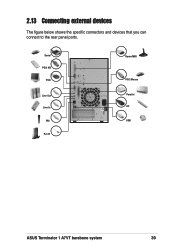
Serial PS/2 KB VGA Line Out Line In Mic RJ-45 Game/MIDI PS/2 Mouse Parallel AC USB ASUS Terminator 1 A7VT barebone system 39 2.13 Connecting external devices The figure below shows the specific connectors and devices that you can connect to the rear panel ports.
Serial PS/2 KB VGA Line Out Line In Mic RJ-45 Game/MIDI PS/2 Mouse Parallel AC USB ASUS Terminator 1 A7VT barebone system 39 2.13 Connecting external devices The figure below shows the specific connectors and devices that you can connect to the rear panel ports.

Terminator A7VT User Manual
Page 40
2.14 Power supply specifications 2.14.1 Input Characteristics Input Voltage Range Range 1 Range 2 Input Frequency Range Maximum Input ac Current Inrush Current Efficiency Min Nom Max 90V 115V 135V 180V ...
2.14 Power supply specifications 2.14.1 Input Characteristics Input Voltage Range Range 1 Range 2 Input Frequency Range Maximum Input ac Current Inrush Current Efficiency Min Nom Max 90V 115V 135V 180V ...
Terminator A7VT User Manual
Page 43
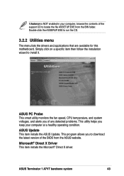
... helps you keep your computer at a healthy operating condition. Simply click on a specific item then follow the installation wizard to download the latest version of the BIOS from the BIN folder. ASUS Terminator 1 A7VT barebone system 43 ASUS Update This item installs the ASUS Update. This program allows you to install it. Microsoft® Direct X Driver...
... helps you keep your computer at a healthy operating condition. Simply click on a specific item then follow the installation wizard to download the latest version of the BIOS from the BIN folder. ASUS Terminator 1 A7VT barebone system 43 ASUS Update This item installs the ASUS Update. This program allows you to install it. Microsoft® Direct X Driver...

Terminator A7VT User Manual
Page 45
The screen image below is for general reference only. The support CD will automatically detect the motherboard information and display it on the motherboard and the contents of the support CD. Motherboard Info Displays the general specifications of the motherboard. Click an icon to display the specified information. 3.2.4 Other information The icons on the top right of the screen give additional information on your screen. ASUS Terminator 1 A7VT barebone system 45
The screen image below is for general reference only. The support CD will automatically detect the motherboard information and display it on the motherboard and the contents of the support CD. Motherboard Info Displays the general specifications of the motherboard. Click an icon to display the specified information. 3.2.4 Other information The icons on the top right of the screen give additional information on your screen. ASUS Terminator 1 A7VT barebone system 45

Terminator A7VT User Manual
Page 62
... PLED +5V Ground Ground Speaker +5 V HDLED NC ExtSMI# Ground PWR Ground Reset Ground A7VT ® A7VT System panel connector HDLED RESET SMI PWRBTN* * Requires an ATX power supply. 62 Chapter 4: Motherboard information These USB connectors comply with USB 2.0 specification that supports up to a slot opening at the back of these connectors, then install...
... PLED +5V Ground Ground Speaker +5 V HDLED NC ExtSMI# Ground PWR Ground Reset Ground A7VT ® A7VT System panel connector HDLED RESET SMI PWRBTN* * Requires an ATX power supply. 62 Chapter 4: Motherboard information These USB connectors comply with USB 2.0 specification that supports up to a slot opening at the back of these connectors, then install...

Terminator A7VT User Manual
Page 73
...Menu" for a field parameter. Use and or the up and down arrow keys to scroll through the entire help In addition to the Item Specific Help window, the BIOS setup program also provides a General Help screen. A sub-menu contains additional options for detailed information on the left) ...text for the currently highlighted field. Use the legend keys to enter values and move the highlight to any menu by simply pressing . ASUS Terminator 1 A7VT barebone system 73 Press to display the first page, press to go to the main menu. This pointer indicates that explanations appear in...
...Menu" for a field parameter. Use and or the up and down arrow keys to scroll through the entire help In addition to the Item Specific Help window, the BIOS setup program also provides a General Help screen. A sub-menu contains additional options for detailed information on the left) ...text for the currently highlighted field. Use the legend keys to enter values and move the highlight to any menu by simply pressing . ASUS Terminator 1 A7VT barebone system 73 Press to display the first page, press to go to the main menu. This pointer indicates that explanations appear in...

Terminator A7VT User Manual
Page 74
... .] IDE Primary Master [Auto] IDE Primary Slave [Pioneer CD-ROM A] IDE Secondary Master [None] IDE Secondary Slave [None] Installed Memory [256 MB] Select Menu Item Specific Help Change the internal clock. 5.3.1 System Time [xx:xx:xx] Sets the system to move between the month, day, and year fields. 5.3.3 Legacy Diskette A [1.44M...
... .] IDE Primary Master [Auto] IDE Primary Slave [Pioneer CD-ROM A] IDE Secondary Master [None] IDE Secondary Slave [None] Installed Memory [256 MB] Select Menu Item Specific Help Change the internal clock. 5.3.1 System Time [xx:xx:xx] Sets the system to move between the month, day, and year fields. 5.3.3 Legacy Diskette A [1.44M...

Terminator A7VT User Manual
Page 75
... options: [Auto] [Mode 0] [Mode 1] [Mode 2] [Mode 3] [Mode 4] ASUS Terminator 1 A7VT barebone system 75 5.3.6 Primary and Secondary Master/Slave IDE Primary Master Primary IDE Master Access Mode Capacity Cylinder Head Sector PIO Mode UDMA Mode Transfer Mode [Auto] [Auto] 0 MB 0 0 0 [Auto] [Auto] None Select Menu Item Specific Help Press [Enter] to recognize the installed hard...
... options: [Auto] [Mode 0] [Mode 1] [Mode 2] [Mode 3] [Mode 4] ASUS Terminator 1 A7VT barebone system 75 5.3.6 Primary and Secondary Master/Slave IDE Primary Master Primary IDE Master Access Mode Capacity Cylinder Head Sector PIO Mode UDMA Mode Transfer Mode [Auto] [Auto] 0 MB 0 0 0 [Auto] [Auto] None Select Menu Item Specific Help Press [Enter] to recognize the installed hard...

Terminator A7VT User Manual
Page 76
CPU Configuration Memory Configuration Chipset PCIPnP Onboard Device Configuration USB Configuration Select Menu Item Specific Help Press [Enter] to malfunction. Take caution when changing the settings of the Advanced menu items. Incorrect field values may cause the system to Set. ...
CPU Configuration Memory Configuration Chipset PCIPnP Onboard Device Configuration USB Configuration Select Menu Item Specific Help Press [Enter] to malfunction. Take caution when changing the settings of the Advanced menu items. Incorrect field values may cause the system to Set. ...

Terminator A7VT User Manual
Page 77
CPU Configuration CPU Type CPU Speed Cache RAM Current FSB Frequency AMD Athlon (tm) 1000 MHz 256 K 100 MHz Select Menu Item Specific Help ASUS Terminator 1 A7VT barebone system 77 5.4.1 CPU configuration The items in this menu show the CPU-related information auto-detected by the BIOS.
CPU Configuration CPU Type CPU Speed Cache RAM Current FSB Frequency AMD Athlon (tm) 1000 MHz 256 K 100 MHz Select Menu Item Specific Help ASUS Terminator 1 A7VT barebone system 77 5.4.1 CPU configuration The items in this menu show the CPU-related information auto-detected by the BIOS.

Terminator A7VT User Manual
Page 78
... set the DRAM timing to CMD (Trcd) 5T DRAM Burst Length [4] DRAM Command Rate [2T Command] Write Recovery Time [3T] tWTR [2T] Select Menu Item Specific Help Set DRAM Frequency. Configuration options: [2T] [3T] tWTR [2T] Sets the tWTR time. 5.4.2 Memory configuration The items in this menu show the memory configuration...
... set the DRAM timing to CMD (Trcd) 5T DRAM Burst Length [4] DRAM Command Rate [2T Command] Write Recovery Time [3T] tWTR [2T] Select Menu Item Specific Help Set DRAM Frequency. Configuration options: [2T] [3T] tWTR [2T] Sets the tWTR time. 5.4.2 Memory configuration The items in this menu show the memory configuration...

Terminator A7VT User Manual
Page 79
... which graphics controller to select the size of 266 MB/s even if you are using an AGP 4X card. Configuration options: [1X] [2X] [4X] ASUS Terminator 1 A7VT barebone system 79 Configuration options: [PCI slot] [AGP] AGP Bridge Configuration This sub-menu allows you to set to boot from the AGP card first... data transfers through the AGP 4X interface card. Chipset AGP Display Switch [Auto] Init Display First [PCI slot] AGP Bridge Configuration Select Menu Item Specific Help AGP Display Switch [Auto] Select [Auto] to display a pop-up menu with the configuration options.
... which graphics controller to select the size of 266 MB/s even if you are using an AGP 4X card. Configuration options: [1X] [2X] [4X] ASUS Terminator 1 A7VT barebone system 79 Configuration options: [PCI slot] [AGP] AGP Bridge Configuration This sub-menu allows you to set to boot from the AGP card first... data transfers through the AGP 4X interface card. Chipset AGP Display Switch [Auto] Init Display First [PCI slot] AGP Bridge Configuration Select Menu Item Specific Help AGP Display Switch [Auto] Select [Auto] to display a pop-up menu with the configuration options.

Terminator A7VT User Manual
Page 81
Select [No] if you need the BIOS to assign an IRQ for VGA [No] [Auto] [Disabled] [Enabled] Select Menu Item Specific Help Plug & Play OS [No] Select [Yes] if you are using standard VGA cards, leave this field to the PCI devices. If you...Some non-standard VGA cards, like graphics accelerators or MPEG video cards, may not show the PCIPnP configuration settings. Configuration options: [Enabled] [Disabled] ASUS Terminator 1 A7VT barebone system 81 5.4.4 PCIPnP The items in this menu show colors properly. Setting this field to automatically configure all the boot and Plug and Play...
Select [No] if you need the BIOS to assign an IRQ for VGA [No] [Auto] [Disabled] [Enabled] Select Menu Item Specific Help Plug & Play OS [No] Select [Yes] if you are using standard VGA cards, leave this field to the PCI devices. If you...Some non-standard VGA cards, like graphics accelerators or MPEG video cards, may not show the PCIPnP configuration settings. Configuration options: [Enabled] [Disabled] ASUS Terminator 1 A7VT barebone system 81 5.4.4 PCIPnP The items in this menu show colors properly. Setting this field to automatically configure all the boot and Plug and Play...

Terminator A7VT User Manual
Page 82
... Game Port Address Midi Port Address x Midi Port IRQ [Disabled] [Auto] [Enabled] [3F8/IRQ4] [378/IRQ7] [ECP+EPP] [EPP1.7] [3] [201] [Disabled] 10 Select Menu Item Specific Help Onboard LAN Boot ROM [Disabled] Allows you to use the onboard LAN feature. Select an item then press to enable or disable the optional...
... Game Port Address Midi Port Address x Midi Port IRQ [Disabled] [Auto] [Enabled] [3F8/IRQ4] [378/IRQ7] [ECP+EPP] [EPP1.7] [3] [201] [Disabled] 10 Select Menu Item Specific Help Onboard LAN Boot ROM [Disabled] Allows you to use the onboard LAN feature. Select an item then press to enable or disable the optional...

Terminator A7VT User Manual
Page 84
... [Enabled] Allows you to enable or disable the EHCI controller. USB Configuration USB 1.1 Controller USB 2.0 Controller USB Legacy Support [Enabled] [Enabled] [Enabled] Select Menu Item Specific Help Enable or Disable the USB 1.1 Controller. 5.4.6 USB configuration The items in the BIOS to turn on automatically when you to display a pop-up menu...
... [Enabled] Allows you to enable or disable the EHCI controller. USB Configuration USB 1.1 Controller USB 2.0 Controller USB Legacy Support [Enabled] [Enabled] [Enabled] Select Menu Item Specific Help Enable or Disable the USB 1.1 Controller. 5.4.6 USB configuration The items in the BIOS to turn on automatically when you to display a pop-up menu...