

Terminator A7VT User Manual
Page 14
This port connects a mouse, modem, or other audio sources. This port connects a VGA monitor. 6. Line Out port. PS/2 mouse port. PS/2 keyboard port. This port connects a joystick or game pad for playing games, ... 1: System introduction VGA port. GAME/MIDI port. Line In port. This Line Out (lime) port connects a headphone or a speaker. This green 6-pin connector is for audio editing. 2. In 6-channel mode, the function of devices. 1 2 3 4 5 6 7 8 9 10 11 12 13 115V/230V Voltage Selector 1. This Line In (light blue) port connects a tape player...
This port connects a mouse, modem, or other audio sources. This port connects a VGA monitor. 6. Line Out port. PS/2 mouse port. PS/2 keyboard port. This port connects a joystick or game pad for playing games, ... 1: System introduction VGA port. GAME/MIDI port. Line In port. This Line Out (lime) port connects a headphone or a speaker. This green 6-pin connector is for audio editing. 2. In 6-channel mode, the function of devices. 1 2 3 4 5 6 7 8 9 10 11 12 13 115V/230V Voltage Selector 1. This Line In (light blue) port connects a tape player...
Terminator A7VT User Manual
Page 15
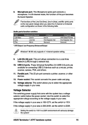
... connects a printer, scanner, or other devices. 12. Use this port becomes Surround Speaker. LAN (RJ-45) port. ASUS Terminator 1 A7VT barebone system 15 The functions of this switch to select the appropriate voltage according to select the appropriate voltage supply in your ...*/Center Front Speaker Out Surround Windows® 98 SE only supports 4.1-channel speaker setting. 9. This switch allows you select the 4-channel or 6-channel audio configuration as a mouse, printer, scanner, camera, PDA, and others. 11. USB 2.0 ports. 8. This Microphone (pink) port connects a microphone...
... connects a printer, scanner, or other devices. 12. Use this port becomes Surround Speaker. LAN (RJ-45) port. ASUS Terminator 1 A7VT barebone system 15 The functions of this switch to select the appropriate voltage according to select the appropriate voltage supply in your ...*/Center Front Speaker Out Surround Windows® 98 SE only supports 4.1-channel speaker setting. 9. This switch allows you select the 4-channel or 6-channel audio configuration as a mouse, printer, scanner, camera, PDA, and others. 11. USB 2.0 ports. 8. This Microphone (pink) port connects a microphone...

Terminator A7VT User Manual
Page 16
The standard components already installed in the system and the locations of the system when you remove the cover and flip out the drive frame. PFC/Non-PFC power supply 7. Two 5.25" drive bays (Optional CD-ROM) 4. 3.5" HDD drive bay 5. 3.5" floppy drive 6. 1.4 Internal components The figure below shows the internal view of the available drive bays are pointed out. USB/audio board 16 Chapter 1: System introduction Motherboard 3. Game/MIDI/COM1 extension module 2. The system may come with either a PFC (Power Factor Correction) or non-PFC power supply. 3 1 4 5 2 6 7 1.
The standard components already installed in the system and the locations of the system when you remove the cover and flip out the drive frame. PFC/Non-PFC power supply 7. Two 5.25" drive bays (Optional CD-ROM) 4. 3.5" HDD drive bay 5. 3.5" floppy drive 6. 1.4 Internal components The figure below shows the internal view of the available drive bays are pointed out. USB/audio board 16 Chapter 1: System introduction Motherboard 3. Game/MIDI/COM1 extension module 2. The system may come with either a PFC (Power Factor Correction) or non-PFC power supply. 3 1 4 5 2 6 7 1.

Terminator A7VT User Manual
Page 30
... usually available for ISA or PCI devices. 2.8.5 IRQ assignments for this motherboard PCI slot AGP slot USB 1.1 UHCI 1 USB 1.1 UHCI 1 USB 1.1 UHCI 1 USB 2.0 EHCI Onboard Audio Onboard LAN ABC - shared - - - - - 2.8.4 Standard interrupt assignments IRQ Priority 0 1 1 2 2 N/A 3* 11 4* 12 5* 13 6 14 7* 15 8 3 9* 4 10* 5 11* 6 12* 7 13 8 14* 9 15* 10 Standard Function System Timer...
... usually available for ISA or PCI devices. 2.8.5 IRQ assignments for this motherboard PCI slot AGP slot USB 1.1 UHCI 1 USB 1.1 UHCI 1 USB 1.1 UHCI 1 USB 2.0 EHCI Onboard Audio Onboard LAN ABC - shared - - - - - 2.8.4 Standard interrupt assignments IRQ Priority 0 1 1 2 2 N/A 3* 11 4* 12 5* 13 6 14 7* 15 8 3 9* 4 10* 5 11* 6 12* 7 13 8 14* 9 15* 10 Standard Function System Timer...

Terminator A7VT User Manual
Page 32
CD-ROM audio cable IDE ribbon cable Red stripe to the black 4-pin connector labeled CD on the cable with the white connector labeled P1. 6. Secondary IDE connector (... ribbon cable to the 4-pin connector at the back of the CD-ROM. Connect one end of the CD-ROM audio cable to the IDE interface at the back of the audio cable to Pin 1 Power cable (P1) 8. Connect the other end of the CD-ROM. 5. Connect a power cable from the power...
CD-ROM audio cable IDE ribbon cable Red stripe to the black 4-pin connector labeled CD on the cable with the white connector labeled P1. 6. Secondary IDE connector (... ribbon cable to the 4-pin connector at the back of the CD-ROM. Connect one end of the CD-ROM audio cable to the IDE interface at the back of the audio cable to Pin 1 Power cable (P1) 8. Connect the other end of the CD-ROM. 5. Connect a power cable from the power...

Terminator A7VT User Manual
Page 59
... floppy ribbon cable to prevent incorrect insertion when using ribbon cables with pin 5 plug). A7VT ® A7VT Floppy disk drive connector 3. Left Audio Channel Ground Right Audio Channel A7VT ® A7VT Internal audio connectors AUX (White) Right Audio Channel Ground CD (Black) Left Audio Channel ASUS Terminator T1 A7VT barebone system 59 Floppy disk drive connector (34-1 pin FLOPPY) This connector supports...
... floppy ribbon cable to prevent incorrect insertion when using ribbon cables with pin 5 plug). A7VT ® A7VT Floppy disk drive connector 3. Left Audio Channel Ground Right Audio Channel A7VT ® A7VT Internal audio connectors AUX (White) Right Audio Channel Ground CD (Black) Left Audio Channel ASUS Terminator T1 A7VT barebone system 59 Floppy disk drive connector (34-1 pin FLOPPY) This connector supports...

Terminator A7VT User Manual
Page 60
... boot up. 5. 4. Find the proper orientation and push down firmly until the connectors completely fit. Front panel audio connector (5-1 pin MIC_LOUT) This connector is for ATX power supply plugs. MIC_LOUT Head set Left channel Head set Right channel GND A7VT 1 1 ® MIC PWR MIC Signal A7VT Front panel audio connector 60 Chapter 4: Motherboard information
... boot up. 5. 4. Find the proper orientation and push down firmly until the connectors completely fit. Front panel audio connector (5-1 pin MIC_LOUT) This connector is for ATX power supply plugs. MIC_LOUT Head set Left channel Head set Right channel GND A7VT 1 1 ® MIC PWR MIC Signal A7VT Front panel audio connector 60 Chapter 4: Motherboard information

Terminator A7VT User Manual
Page 82
...] Allows you disable this menu show the onboard device configuration settings. If you to enable or disable the onboard AC97 Audio controller. Set to [Disabled] if you wish to enable or disable the onboard LAN controller. Configuration options: [Disabled] [378/ IRQ7] [278/IRQ5] [3BC/IRQ7]... configuration The items in this field, the Parallel Port Mode and ECP DMA Select configurations are not available. PCIPnP Onboard LAN Boot ROM AC97 Audio Onboard LAN Serial Port1 Address Parallel Port Address Parallel Port Mode EPP Mode Select ECP Mode Use DMA Game Port Address Midi Port Address x ...
...] Allows you disable this menu show the onboard device configuration settings. If you to enable or disable the onboard AC97 Audio controller. Set to [Disabled] if you wish to enable or disable the onboard LAN controller. Configuration options: [Disabled] [378/ IRQ7] [278/IRQ5] [3BC/IRQ7]... configuration The items in this field, the Parallel Port Mode and ECP DMA Select configurations are not available. PCIPnP Onboard LAN Boot ROM AC97 Audio Onboard LAN Serial Port1 Address Parallel Port Address Parallel Port Mode EPP Mode Select ECP Mode Use DMA Game Port Address Midi Port Address x ...