
TR-DLS User Manual
Page 2
...INACCURACIES THAT MAY APPEAR IN THIS MANUAL, INCLUDING THE PRODUCTS AND SOFTWARE DESCRIBED IN IT. Product Name: ASUS TR-DLS Manual Revision: 3.00 E887 Release Date: November 2001 2 ASUS TR-DLS User's Manual The product name and revision number are represented by the third digit in writing by... ASUS; Manual revisions are released for each product design represented by the purchaser for identification or explanation and to ...
...INACCURACIES THAT MAY APPEAR IN THIS MANUAL, INCLUDING THE PRODUCTS AND SOFTWARE DESCRIBED IN IT. Product Name: ASUS TR-DLS Manual Revision: 3.00 E887 Release Date: November 2001 2 ASUS TR-DLS User's Manual The product name and revision number are represented by the third digit in writing by... ASUS; Manual revisions are released for each product design represented by the purchaser for identification or explanation and to ...
TR-DLS User Manual
Page 3
... Road, Peitou, Taipei, Taiwan 112 General Tel: +886-2-2894-3447 General Fax: +886-2-2894-3449 General Email: info@asus.com.tw Technical Support MB/Others (Tel): +886-2-2890-7121 (English) Notebook (Tel): +886-2-2890-7122 (English) ...): +886-2-2890-7123 (English) Support Fax: +886-2-2890-7698 Support Email: tsd@asus.com.tw Web Site: www.asus.com.tw Newsgroup: cscnews.asus.com.tw ASUS COMPUTER INTERNATIONAL (America) Address: 6737 Mowry Avenue, Mowry Business Center, Building 2, Newark,...de/support (for online support) Web Site: www.asuscom.de ASUS TR-DLS User's Manual 3
... Road, Peitou, Taipei, Taiwan 112 General Tel: +886-2-2894-3447 General Fax: +886-2-2894-3449 General Email: info@asus.com.tw Technical Support MB/Others (Tel): +886-2-2890-7121 (English) Notebook (Tel): +886-2-2890-7122 (English) ...): +886-2-2890-7123 (English) Support Fax: +886-2-2890-7698 Support Email: tsd@asus.com.tw Web Site: www.asus.com.tw Newsgroup: cscnews.asus.com.tw ASUS COMPUTER INTERNATIONAL (America) Address: 6737 Mowry Avenue, Mowry Business Center, Building 2, Newark,...de/support (for online support) Web Site: www.asuscom.de ASUS TR-DLS User's Manual 3

TR-DLS User Manual
Page 4
... 4.1.1 Upon First Use of the Computer System 41 4.1.2 Updating BIOS Procedures 43 4.2 BIOS Setup Program 45 4.2.1 BIOS Menu Bar 46 4.2.2 Legend Bar 46 4 ASUS TR-DLS User's Manual HARDWARE SETUP 14 3.1 TR-DLS Motherboard Layout 14 3.2 Layout Contents 15 3.3 Hardware Setup Procedure 17 3.4 Motherboard Settings 18 3.4.1 Switches 18 3.4.2 Jumpers 21 3.5 System Memory 23 3.5.1 Memory Configurations...
... 4.1.1 Upon First Use of the Computer System 41 4.1.2 Updating BIOS Procedures 43 4.2 BIOS Setup Program 45 4.2.1 BIOS Menu Bar 46 4.2.2 Legend Bar 46 4 ASUS TR-DLS User's Manual HARDWARE SETUP 14 3.1 TR-DLS Motherboard Layout 14 3.2 Layout Contents 15 3.3 Hardware Setup Procedure 17 3.4 Motherboard Settings 18 3.4.1 Switches 18 3.4.2 Jumpers 21 3.5 System Memory 23 3.5.1 Memory Configurations...
TR-DLS User Manual
Page 5
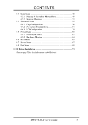
CONTENTS 4.3 Main Menu 48 4.3.1 Primary & Secondary Master/Slave 49 4.3.2 Keyboard Features 52 4.4 Advanced Menu 54 4.4.1 Chip Configuration 56 4.4.2 I/O Device Configuration 57 4.4.3 PCI Configuration 58 4.5 Power Menu 60 4.5.1 Power Up Control 62 4.5.2 Hardware Monitor 64 4.6 Boot Menu 65 4.7 Server Menu 67 4.8 Exit Menu 68 5. OS Driver Installation 71 (Turn to page 72 for detailed contents on OS Drivers) ASUS TR-DLS User's Manual 5
CONTENTS 4.3 Main Menu 48 4.3.1 Primary & Secondary Master/Slave 49 4.3.2 Keyboard Features 52 4.4 Advanced Menu 54 4.4.1 Chip Configuration 56 4.4.2 I/O Device Configuration 57 4.4.3 PCI Configuration 58 4.5 Power Menu 60 4.5.1 Power Up Control 62 4.5.2 Hardware Monitor 64 4.6 Boot Menu 65 4.7 Server Menu 67 4.8 Exit Menu 68 5. OS Driver Installation 71 (Turn to page 72 for detailed contents on OS Drivers) ASUS TR-DLS User's Manual 5

TR-DLS User Manual
Page 6
... does not exceed the Class B limits for help. Cet appareil numérique de la classe B est conforme à la norme NMB-003 du Canada. 6 ASUS TR-DLS User's Manual WARNING! Any changes or modifications to this equipment does cause harmful interference to radio or television reception, which the receiver is no guarantee...
... does not exceed the Class B limits for help. Cet appareil numérique de la classe B est conforme à la norme NMB-003 du Canada. 6 ASUS TR-DLS User's Manual WARNING! Any changes or modifications to this equipment does cause harmful interference to radio or television reception, which the receiver is no guarantee...
TR-DLS User Manual
Page 7
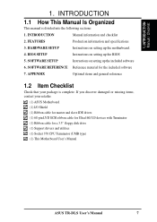
... 6. INTRODUCTION Manual / Checklist 1. SOFTWARE REFERENCE Reference material for a 3.5" floppy disk drive (1) Support drivers and utilities (1) Socket 370 CPU Terminator (UMB type) (1) This Motherboard User's Manual ASUS TR-DLS User's Manual 7 FEATURES Production information and specifications 3. APPENDIX Optional items and general reference 1.2 Item Checklist Check that your retailer...
... 6. INTRODUCTION Manual / Checklist 1. SOFTWARE REFERENCE Reference material for a 3.5" floppy disk drive (1) Support drivers and utilities (1) Socket 370 CPU Terminator (UMB type) (1) This Motherboard User's Manual ASUS TR-DLS User's Manual 7 FEATURES Production information and specifications 3. APPENDIX Optional items and general reference 1.2 Item Checklist Check that your retailer...
TR-DLS User Manual
Page 8
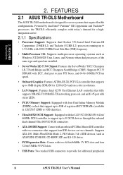
Powered by dual Intel® Pentium® III Coppermine and Tualatin™ processors, the TR-DLS efficiently complies with today's demand for a highintegration server. 2.1.1 Specifications • Processor Support: Supports dual Socket 370-based ...IDE Support: Comes with an onboard PCI Bus Master IDE controller with two connectors that require flexible configurations. FEATURES 2.1 ASUS TR-DLS Motherboard The ASUS TR-DLS motherboard is designed for additional peripherals 8 ASUS TR-DLS User's Manual Supports ATA-100, Multi-Word DMA Mode 2, PIO Modes 3 & 4 IDE devices, such as ...
Powered by dual Intel® Pentium® III Coppermine and Tualatin™ processors, the TR-DLS efficiently complies with today's demand for a highintegration server. 2.1.1 Specifications • Processor Support: Supports dual Socket 370-based ...IDE Support: Comes with an onboard PCI Bus Master IDE controller with two connectors that require flexible configurations. FEATURES 2.1 ASUS TR-DLS Motherboard The ASUS TR-DLS motherboard is designed for additional peripherals 8 ASUS TR-DLS User's Manual Supports ATA-100, Multi-Word DMA Mode 2, PIO Modes 3 & 4 IDE devices, such as ...
TR-DLS User Manual
Page 9
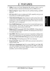
...Flash EEPROM), offering enhanced ACPI for Windows NT/2000/XP compatibility, and autodetection of most devices for a separate IOAPIC chip. • ASUS Server Management Card: The optional ASMC-LE and ASMC-ME cards support Intelligent Platform Management Interface (IPMI), system health monitor, and LAN... firmware gives a new easy-to-use interface which is used to achieve server reliability, availability, and serviceability requirements. ASUS TR-DLS User's Manual 9 Provides boot block write protection, and HD/SCSI/MO/ZIP/CD/Floppy boot selection. FEATURES Optional Components 2.
...Flash EEPROM), offering enhanced ACPI for Windows NT/2000/XP compatibility, and autodetection of most devices for a separate IOAPIC chip. • ASUS Server Management Card: The optional ASMC-LE and ASMC-ME cards support Intelligent Platform Management Interface (IPMI), system health monitor, and LAN... firmware gives a new easy-to-use interface which is used to achieve server reliability, availability, and serviceability requirements. ASUS TR-DLS User's Manual 9 Provides boot block write protection, and HD/SCSI/MO/ZIP/CD/Floppy boot selection. FEATURES Optional Components 2.
TR-DLS User Manual
Page 10
... increases the data transfer rate up to 1064MB/s. • ACPI Ready: Advanced Configuration and Power Interface (ACPI) is also implemented on all ASUS smart series motherboards. With these features implemented in the OS, PCs can handle rates up to (4) 32-bit 33MHz PCI busses. •...8226; New Compliancy: Both the BIOS and hardware levels of ACPI, an ACPI-supported OS, such as required by PC '99. 10 ASUS TR-DLS User's Manual ACPI provides more Energy Saving Features for configuring and managing all the energy saving standards. Color-coded connectors and descriptive icons make ...
... increases the data transfer rate up to 1064MB/s. • ACPI Ready: Advanced Configuration and Power Interface (ACPI) is also implemented on all ASUS smart series motherboards. With these features implemented in the OS, PCs can handle rates up to (4) 32-bit 33MHz PCI busses. •...8226; New Compliancy: Both the BIOS and hardware levels of ACPI, an ACPI-supported OS, such as required by PC '99. 10 ASUS TR-DLS User's Manual ACPI provides more Energy Saving Features for configuring and managing all the energy saving standards. Color-coded connectors and descriptive icons make ...
TR-DLS User Manual
Page 11
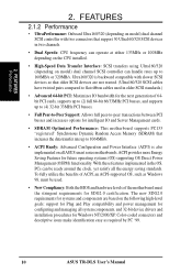
...Connectors for future processors, so monitoring is necessary to present enormous user interfaces and run large applications. The onboard hardware ASUS ASIC, in conjunction with server reliability, availability, and serviceability requirements. Remote management response via remote diagnostics and troubleshooting still...Soft-Off mode. • Remote Ring In (requires modem): This allows a computer to wake up to critical motherboard components. ASUS TR-DLS User's Manual 11 Regardless of the setting, pushing the power button for RPM and failure. Suspend or Sleep) button or as the...
...Connectors for future processors, so monitoring is necessary to present enormous user interfaces and run large applications. The onboard hardware ASUS ASIC, in conjunction with server reliability, availability, and serviceability requirements. Remote management response via remote diagnostics and troubleshooting still...Soft-Off mode. • Remote Ring In (requires modem): This allows a computer to wake up to critical motherboard components. ASUS TR-DLS User's Manual 11 Regardless of the setting, pushing the power button for RPM and failure. Suspend or Sleep) button or as the...
TR-DLS User Manual
Page 12
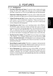
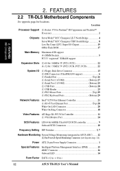
x 10 in . FEATURES 2.2 TR-DLS Motherboard Components See opposite page for Pentium® III Coppermine and Tualatin™ Processors 2 Chipsets ServerWorks® RCC Champion LE-T North Bridge 4 ServerWorks®... Monitoring System Voltage Monitoring (integrated in ASUS ASIC) ....... 12 (4) Fan Power & Speed Monitoring Connectors (see layout on p. 14) Power ATX 24-pin Power Supply Connector 1 Special Features Intelligent Platform Management Interface (IPMI 15 eRMC Connector 16 Onboard LED 14 Form Factor EATX (12 in .) 12 ASUS TR-DLS User's Manual 2. FEATURES MB Components...
x 10 in . FEATURES 2.2 TR-DLS Motherboard Components See opposite page for Pentium® III Coppermine and Tualatin™ Processors 2 Chipsets ServerWorks® RCC Champion LE-T North Bridge 4 ServerWorks®... Monitoring System Voltage Monitoring (integrated in ASUS ASIC) ....... 12 (4) Fan Power & Speed Monitoring Connectors (see layout on p. 14) Power ATX 24-pin Power Supply Connector 1 Special Features Intelligent Platform Management Interface (IPMI 15 eRMC Connector 16 Onboard LED 14 Form Factor EATX (12 in .) 12 ASUS TR-DLS User's Manual 2. FEATURES MB Components...
TR-DLS User Manual
Page 14
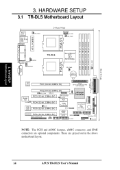
...(72-bit, 168-pin module) DIMM Socket 3 (72-bit, 168-pin module) CHA_FAN2 PGA 370 PARALLEL PORT ATX_POWER KBPWR COM2 CHASSIS USBPORT TR-DLS ServerWorks® RCC LE-T North Bridge CPU_FAN2 PGA 370 VGA CR2032 3V Lithium Cell CMOS Power 01 23 45 67 SCSI-B 68-Pin Ultra160/... South Bridge BUZZER ASUS ASIC PCI6 (32-bit, 33MHz 5V) with Hardware Monitor BPSMB Primary IDE1 Secondary IDE2 eRMC CONNECTOR IPMI FLOPPY PANEL HD_LED NOTE: The SCSI and ASMC features, eRMC connector, and IPMI connectors are grayed out in the above motherboard layout. 14 ASUS TR-DLS User's Manual H/W...
...(72-bit, 168-pin module) DIMM Socket 3 (72-bit, 168-pin module) CHA_FAN2 PGA 370 PARALLEL PORT ATX_POWER KBPWR COM2 CHASSIS USBPORT TR-DLS ServerWorks® RCC LE-T North Bridge CPU_FAN2 PGA 370 VGA CR2032 3V Lithium Cell CMOS Power 01 23 45 67 SCSI-B 68-Pin Ultra160/... South Bridge BUZZER ASUS ASIC PCI6 (32-bit, 33MHz 5V) with Hardware Monitor BPSMB Primary IDE1 Secondary IDE2 eRMC CONNECTOR IPMI FLOPPY PANEL HD_LED NOTE: The SCSI and ASMC features, eRMC connector, and IPMI connectors are grayed out in the above motherboard layout. 14 ASUS TR-DLS User's Manual H/W...
TR-DLS User Manual
Page 15
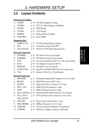
... p. 36 SMBus Connectors (two 6-1 pins) 10 USBPORT p. 36 Universal Serial Port Header (10-1pin male) 11) ATXPWR p. 37 ATX Power Supply Connector (20/24-pin) ASUS TR-DLS User's Manual 15 3. H/W SETUP Layout Contents 3.
... p. 36 SMBus Connectors (two 6-1 pins) 10 USBPORT p. 36 Universal Serial Port Header (10-1pin male) 11) ATXPWR p. 37 ATX Power Supply Connector (20/24-pin) ASUS TR-DLS User's Manual 15 3. H/W SETUP Layout Contents 3.
TR-DLS User Manual
Page 16
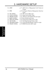
3. HARDWARE SETUP 12) eRMC p. 37 ASUS Server Management Card Connector (50-pin) 13) IPMI p. 38 Intelligent Platform Management Interface (4-pin) 14) NIC (PANEL) p. 38 NIC Activity LED (2-pin) 15) STATUS (PANEL) p. ... Interrupt Switch (2-pin) 20) SPEAKER (PANEL) p. 39 System Warning Speaker Connector (4-pin) 21) IDELED (PANEL) p. 39 IDE/SCSI Activity LED (2-pin) 3. H/W SETUP Motherboard Settings 16 ASUS TR-DLS User's Manual
3. HARDWARE SETUP 12) eRMC p. 37 ASUS Server Management Card Connector (50-pin) 13) IPMI p. 38 Intelligent Platform Management Interface (4-pin) 14) NIC (PANEL) p. 38 NIC Activity LED (2-pin) 15) STATUS (PANEL) p. ... Interrupt Switch (2-pin) 20) SPEAKER (PANEL) p. 39 System Warning Speaker Connector (4-pin) 21) IDELED (PANEL) p. 39 IDE/SCSI Activity LED (2-pin) 3. H/W SETUP Motherboard Settings 16 ASUS TR-DLS User's Manual
TR-DLS User Manual
Page 17
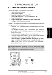
... system is either ON, in sleep mode, or in the bag that theATX power supply is turned OFF before using your computer: 1. H/W SETUP Motherboard Settings TR-DLS TR-DLS Onboard LED LED1 ON Standby Power OFF Powered Off ASUS TR-DLS User's Manual 17
... system is either ON, in sleep mode, or in the bag that theATX power supply is turned OFF before using your computer: 1. H/W SETUP Motherboard Settings TR-DLS TR-DLS Onboard LED LED1 ON Standby Power OFF Powered Off ASUS TR-DLS User's Manual 17

TR-DLS User Manual
Page 18
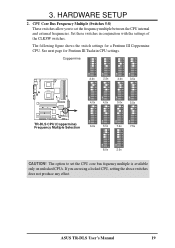
... the DIP switches on a DIP switch represents the ON or OFF position. Frequency Multiple ON OFF 1. CLKSW TR-DLS ON ON CPU 12345 100MHz 12345 133MHz TR-DLS CPU External Frequency Selection CAUTION! The figure below shows the location of the CPU external frequency (or bus clock... CPU speed). Frequencies other than the recommended CPU bus frequencies are not guaranteed to be stable. 18 ASUS TR-DLS User's Manual Frequency Selection 4. 3. Frequency Selection 2. Frequency Selection 3. Frequency Selection 1. External Buzzer Setting 3. Frequency Multiple 7.
... the DIP switches on a DIP switch represents the ON or OFF position. Frequency Multiple ON OFF 1. CLKSW TR-DLS ON ON CPU 12345 100MHz 12345 133MHz TR-DLS CPU External Frequency Selection CAUTION! The figure below shows the location of the CPU external frequency (or bus clock... CPU speed). Frequencies other than the recommended CPU bus frequencies are not guaranteed to be stable. 18 ASUS TR-DLS User's Manual Frequency Selection 4. 3. Frequency Selection 2. Frequency Selection 3. Frequency Selection 1. External Buzzer Setting 3. Frequency Multiple 7.
TR-DLS User Manual
Page 19
...The following figure shows the switch settings for Pentium III Tualatin CPU settings. See next page for a Pentium III Coppermine CPU. ASUS TR-DLS User's Manual 19 Set these switches in conjunction with the settings of the CLKSW switches. Coppermine ON 12345678 ON 12345678 ON ...12345678 ON 12345678 ON 12345678 ON 12345678 ON 12345678 ON 12345678 2.0x 2.5x 3.0x 3.5x TR-DLS 4.0x 4.5x 5.0x 5.5x ON 12345678 ON 12345678 ON 12345678 ON 12345678 TR-DLS CPU (Coppermine) Frequency Multiple Selection 6.0x 6.5x 7.0x 7.5x ON 12345678 ON 12345678 8.0x 2.0x CAUTION...
...The following figure shows the switch settings for Pentium III Tualatin CPU settings. See next page for a Pentium III Coppermine CPU. ASUS TR-DLS User's Manual 19 Set these switches in conjunction with the settings of the CLKSW switches. Coppermine ON 12345678 ON 12345678 ON ...12345678 ON 12345678 ON 12345678 ON 12345678 ON 12345678 ON 12345678 2.0x 2.5x 3.0x 3.5x TR-DLS 4.0x 4.5x 5.0x 5.5x ON 12345678 ON 12345678 ON 12345678 ON 12345678 TR-DLS CPU (Coppermine) Frequency Multiple Selection 6.0x 6.5x 7.0x 7.5x ON 12345678 ON 12345678 8.0x 2.0x CAUTION...

TR-DLS User Manual
Page 20
... the CPU core bus frequency settings for Pentium III Tualatin CPU. Set to ON to activate the external buzzer. TR-DLS ON 12345678 ON: Enable OFF: Disable TR-DLS External Buzzer Setting External Buzzer 20 ASUS TR-DLS User's Manual Set to OFF to disable the buzzer. H/W SETUP Motherboard Settings 3. Tualatin ON 12345678 ON 12345678 ON 12345678...
... the CPU core bus frequency settings for Pentium III Tualatin CPU. Set to ON to activate the external buzzer. TR-DLS ON 12345678 ON: Enable OFF: Disable TR-DLS External Buzzer Setting External Buzzer 20 ASUS TR-DLS User's Manual Set to OFF to disable the buzzer. H/W SETUP Motherboard Settings 3. Tualatin ON 12345678 ON 12345678 ON 12345678...
TR-DLS User Manual
Page 21
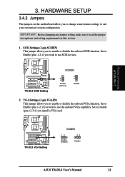
Before changing any jumper setting, make sure to enable or disable the onboard VGA function. TR-DLS TR-DLS SCSI Setting SCSIEN 2 1 Enable (Default) 3 2 Disable 2. TR-DLS TR-DLS VGA Setting VGAEN 12 Enable (Default) 23 Disable ASUS TR-DLS User's Manual 21 HARDWARE SETUP 3.4.2 Jumpers The jumpers on the motherboard allow you to suit your customized system configuration. SCSI Settings (3-pin...
Before changing any jumper setting, make sure to enable or disable the onboard VGA function. TR-DLS TR-DLS SCSI Setting SCSIEN 2 1 Enable (Default) 3 2 Disable 2. TR-DLS TR-DLS VGA Setting VGAEN 12 Enable (Default) 23 Disable ASUS TR-DLS User's Manual 21 HARDWARE SETUP 3.4.2 Jumpers The jumpers on the motherboard allow you to suit your customized system configuration. SCSI Settings (3-pin...

TR-DLS User Manual
Page 22
... and enter BIOS setup to Clear CMOS PCI3 (32-bit, 33MHz 5V) PCI4 (32-bit, 33MHz 5V) TR-DLS Clear RTC RAM 22 ASUS TR-DLS User's Manual 3. Remove the battery. 3. H/W SETUP Motherboard Settings TR-DLS KBPWR 2 1 5V (Default) 3 2 5VSB TR-DLS Keyboard Power Setting 4. The RAM data that can clear the CMOS memory of date, time, and system...
... and enter BIOS setup to Clear CMOS PCI3 (32-bit, 33MHz 5V) PCI4 (32-bit, 33MHz 5V) TR-DLS Clear RTC RAM 22 ASUS TR-DLS User's Manual 3. Remove the battery. 3. H/W SETUP Motherboard Settings TR-DLS KBPWR 2 1 5V (Default) 3 2 5VSB TR-DLS Keyboard Power Setting 4. The RAM data that can clear the CMOS memory of date, time, and system...


