

TR-DLS User Manual
Page 1
® TR-DLS Dual Socket 370 Motherboard USER'S MANUAL
® TR-DLS Dual Socket 370 Motherboard USER'S MANUAL

TR-DLS User Manual
Page 4
...This Manual Is Organized 7 1.2 Item Checklist 7 2. HARDWARE SETUP 14 3.1 TR-DLS Motherboard Layout 14 3.2 Layout Contents 15 3.3 Hardware Setup Procedure 17 3.4 Motherboard Settings 18 3.4.1 Switches 18 3.4.2 Jumpers 21 3.5 System Memory 23 3.5.1 Memory... 29 3.8.2 Internal Connectors 31 3.9 Starting Up the First Time 40 4. CONTENTS 1. FEATURES 8 2.1 ASUS TR-DLS Motherboard 8 2.1.1 Specifications 8 2.1.2 Performance 10 2.1.3 Intelligence 11 2.2 TR-DLS Motherboard Components 12 2.2.1 Component Locations 13 3. BIOS SETUP 41 4.1 Managing and Updating Your BIOS 41 4.1.1 ...
...This Manual Is Organized 7 1.2 Item Checklist 7 2. HARDWARE SETUP 14 3.1 TR-DLS Motherboard Layout 14 3.2 Layout Contents 15 3.3 Hardware Setup Procedure 17 3.4 Motherboard Settings 18 3.4.1 Switches 18 3.4.2 Jumpers 21 3.5 System Memory 23 3.5.1 Memory... 29 3.8.2 Internal Connectors 31 3.9 Starting Up the First Time 40 4. CONTENTS 1. FEATURES 8 2.1 ASUS TR-DLS Motherboard 8 2.1.1 Specifications 8 2.1.2 Performance 10 2.1.3 Intelligence 11 2.2 TR-DLS Motherboard Components 12 2.2.1 Component Locations 13 3. BIOS SETUP 41 4.1 Managing and Updating Your BIOS 41 4.1.1 ...
TR-DLS User Manual
Page 7
... Optional items and general reference 1.2 Item Checklist Check that your retailer. (1) ASUS Motherboard (1) I/O Shield (1) Ribbon cable for master and slave IDE drives (1) 68... Manual / Checklist 1. BIOS SETUP Instructions on setting up the included software 6. SOFTWARE SETUP Instructions on setting up the motherboard. 4. If you discover damaged or missing items, contact your package is divided into the following sections: 1. HARDWARE SETUP... Support drivers and utilities (1) Socket 370 CPU Terminator (UMB type) (1) This Motherboard User's Manual ASUS TR-DLS User's Manual 7
... Optional items and general reference 1.2 Item Checklist Check that your retailer. (1) ASUS Motherboard (1) I/O Shield (1) Ribbon cable for master and slave IDE drives (1) 68... Manual / Checklist 1. BIOS SETUP Instructions on setting up the included software 6. SOFTWARE SETUP Instructions on setting up the motherboard. 4. If you discover damaged or missing items, contact your package is divided into the following sections: 1. HARDWARE SETUP... Support drivers and utilities (1) Socket 370 CPU Terminator (UMB type) (1) This Motherboard User's Manual ASUS TR-DLS User's Manual 7
TR-DLS User Manual
Page 8
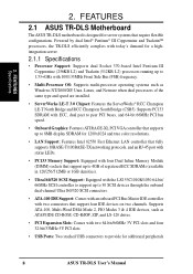
Powered by dual Intel® Pentium® III Coppermine and Tualatin™ processors, the TR-DLS efficiently complies with today's demand for 1280x1024 and true color resolutions. • LAN Support: Features Intel 82550 Fast Ethernet LAN controller that fully ...ECC SDRAMs (available in 128/256/512MB or 1GB densities). • Ultra160/320 SCSI Support: Equipped with two connectors that require flexible configurations. 2. FEATURES 2.1 ASUS TR-DLS Motherboard The ASUS TR-DLS motherboard is designed for additional peripherals 8 ASUS TR-DLS User's Manual FEATURES Specifications 2.
Powered by dual Intel® Pentium® III Coppermine and Tualatin™ processors, the TR-DLS efficiently complies with today's demand for 1280x1024 and true color resolutions. • LAN Support: Features Intel 82550 Fast Ethernet LAN controller that fully ...ECC SDRAMs (available in 128/256/512MB or 1GB densities). • Ultra160/320 SCSI Support: Equipped with two connectors that require flexible configurations. 2. FEATURES 2.1 ASUS TR-DLS Motherboard The ASUS TR-DLS motherboard is designed for additional peripherals 8 ASUS TR-DLS User's Manual FEATURES Specifications 2.
TR-DLS User Manual
Page 9
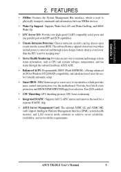
Provides boot block write protection, and HD/SCSI/MO/ZIP/CD/Floppy boot selection. ASUS TR-DLS User's Manual 9 2. FEATURES Optional Components 2. FEATURES • SMBus: Features the System Management Bus interface, which is even lower than the RTC... Platform Management Interface (IPMI), system health monitor, and LAN security mode solutions to -use interface which provides more control and protection over the motherboard. Year 2000 certified. • CPU Throttling: CPU throttling protects CPU from overheating. • Integrated IOAPIC: Supports full 32-APIC entries and...
Provides boot block write protection, and HD/SCSI/MO/ZIP/CD/Floppy boot selection. ASUS TR-DLS User's Manual 9 2. FEATURES Optional Components 2. FEATURES • SMBus: Features the System Management Bus interface, which is even lower than the RTC... Platform Management Interface (IPMI), system health monitor, and LAN security mode solutions to -use interface which provides more control and protection over the motherboard. Year 2000 certified. • CPU Throttling: CPU throttling protects CPU from overheating. • Integrated IOAPIC: Supports full 32-APIC entries and...
TR-DLS User Manual
Page 10
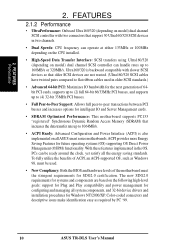
... Play compatibility and power management for the next generation of ACPI, an ACPI-supported OS, such as required by PC '99. 10 ASUS TR-DLS User's Manual With these features implemented in the OS, PCs can be used in two channels. • Dual Speeds: CPU frequency... peer-to-peer transactions between PCI busses and increases options for intelligent IO and Server Management cards. • SDRAM Optimized Performance: This motherboard supports PC133 "registered" Synchronous Dynamic Random Access Memory (SDRAM) that support 30 Ultra160/320 SCSI devices in older SCSI standards.) •...
... Play compatibility and power management for the next generation of ACPI, an ACPI-supported OS, such as required by PC '99. 10 ASUS TR-DLS User's Manual With these features implemented in the OS, PCs can be used in two channels. • Dual Speeds: CPU frequency... peer-to-peer transactions between PCI busses and increases options for intelligent IO and Server Management cards. • SDRAM Optimized Performance: This motherboard supports PC133 "registered" Synchronous Dynamic Random Access Memory (SDRAM) that support 30 Ultra160/320 SCSI devices in older SCSI standards.) •...
TR-DLS User Manual
Page 11
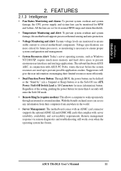
... possible application crashes. Regardless of the setting, pushing the power button for more memory and hard drive space to critical motherboard components. With this motherboard supports processor thermal sensing and auto-protection. • Voltage Monitoring and Alert: System voltage levels are more critical for RPM... ensure proper system configuration and management. • System Resources Alert: Today's server operating systems, such as the "Stand by" (a.k.a. ASUS TR-DLS User's Manual 11 All the fans are used up remotely through an internal or external modem. 2.
... possible application crashes. Regardless of the setting, pushing the power button for more memory and hard drive space to critical motherboard components. With this motherboard supports processor thermal sensing and auto-protection. • Voltage Monitoring and Alert: System voltage levels are more critical for RPM... ensure proper system configuration and management. • System Resources Alert: Today's server operating systems, such as the "Stand by" (a.k.a. ASUS TR-DLS User's Manual 11 All the fans are used up remotely through an internal or external modem. 2.
TR-DLS User Manual
Page 12
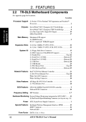
FEATURES 2.2 TR-DLS Motherboard Components See opposite page for Pentium® III Coppermine and Tualatin™ Processors 2 Chipsets ServerWorks® RCC Champion LE-T North Bridge 4 ServerWorks® RCC Champion ... 24-pin Power Supply Connector 1 Special Features Intelligent Platform Management Interface (IPMI 15 eRMC Connector 16 Onboard LED 14 Form Factor EATX (12 in .) 12 ASUS TR-DLS User's Manual FEATURES MB Components 2. x 10 in . 2. Location Processor Support (2) Socket 370 for locations.
FEATURES 2.2 TR-DLS Motherboard Components See opposite page for Pentium® III Coppermine and Tualatin™ Processors 2 Chipsets ServerWorks® RCC Champion LE-T North Bridge 4 ServerWorks® RCC Champion ... 24-pin Power Supply Connector 1 Special Features Intelligent Platform Management Interface (IPMI 15 eRMC Connector 16 Onboard LED 14 Form Factor EATX (12 in .) 12 ASUS TR-DLS User's Manual FEATURES MB Components 2. x 10 in . 2. Location Processor Support (2) Socket 370 for locations.
TR-DLS User Manual
Page 14
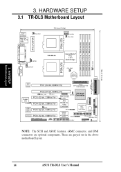
30.5cm (12in) 3. H/W SETUP Motherboard Layout 3. HARDWARE SETUP 3.1 TR-DLS Motherboard Layout PS/2 T: Mouse B: Keyboard Bottom: Top: USB1 RJ-45 USB2 COM1 CHA_FAN1 24.4cm (9.6in) 12345 CLKSW CPU_FAN1 DIMM Socket 0 (72-bit, 168-pin module)...; RCC CSB5 South Bridge BUZZER ASUS ASIC PCI6 (32-bit, 33MHz 5V) with Hardware Monitor BPSMB Primary IDE1 Secondary IDE2 eRMC CONNECTOR IPMI FLOPPY PANEL HD_LED NOTE: The SCSI and ASMC features, eRMC connector, and IPMI connectors are grayed out in the above motherboard layout. 14 ASUS TR-DLS User's Manual These are optional ...
30.5cm (12in) 3. H/W SETUP Motherboard Layout 3. HARDWARE SETUP 3.1 TR-DLS Motherboard Layout PS/2 T: Mouse B: Keyboard Bottom: Top: USB1 RJ-45 USB2 COM1 CHA_FAN1 24.4cm (9.6in) 12345 CLKSW CPU_FAN1 DIMM Socket 0 (72-bit, 168-pin module)...; RCC CSB5 South Bridge BUZZER ASUS ASIC PCI6 (32-bit, 33MHz 5V) with Hardware Monitor BPSMB Primary IDE1 Secondary IDE2 eRMC CONNECTOR IPMI FLOPPY PANEL HD_LED NOTE: The SCSI and ASMC features, eRMC connector, and IPMI connectors are grayed out in the above motherboard layout. 14 ASUS TR-DLS User's Manual These are optional ...
TR-DLS User Manual
Page 15
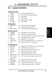
H/W SETUP Layout Contents 3. 3. HARDWARE SETUP 3.2 Layout Contents Motherboard Settings 1) CLKSW p. 18 CPU Bus Frequency Setting 2) CONFIG p. 19 CPU Core Bus Frequency Multiplier 3) SCSIEN p. 21 SCSI Setting 4) VGAEN p. 21 VGA Setting 5) KBPWR p. 22 Keyboard ... p. 36 SMBus Connectors (two 6-1 pins) 10 USBPORT p. 36 Universal Serial Port Header (10-1pin male) 11) ATXPWR p. 37 ATX Power Supply Connector (20/24-pin) ASUS TR-DLS User's Manual 15
H/W SETUP Layout Contents 3. 3. HARDWARE SETUP 3.2 Layout Contents Motherboard Settings 1) CLKSW p. 18 CPU Bus Frequency Setting 2) CONFIG p. 19 CPU Core Bus Frequency Multiplier 3) SCSIEN p. 21 SCSI Setting 4) VGAEN p. 21 VGA Setting 5) KBPWR p. 22 Keyboard ... p. 36 SMBus Connectors (two 6-1 pins) 10 USBPORT p. 36 Universal Serial Port Header (10-1pin male) 11) ATXPWR p. 37 ATX Power Supply Connector (20/24-pin) ASUS TR-DLS User's Manual 15
TR-DLS User Manual
Page 16
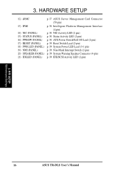
HARDWARE SETUP 12) eRMC p. 37 ASUS Server Management Card Connector (50-pin) 13) IPMI p. 38 Intelligent Platform Management Interface (4-pin) 14) NIC (PANEL) p. 38 NIC Activity LED (2-pin) 15) STATUS (PANEL) p. ...) p. 39 Non-Mask Interrupt Switch (2-pin) 20) SPEAKER (PANEL) p. 39 System Warning Speaker Connector (4-pin) 21) IDELED (PANEL) p. 39 IDE/SCSI Activity LED (2-pin) 3. H/W SETUP Motherboard Settings 16 ASUS TR-DLS User's Manual 3.
HARDWARE SETUP 12) eRMC p. 37 ASUS Server Management Card Connector (50-pin) 13) IPMI p. 38 Intelligent Platform Management Interface (4-pin) 14) NIC (PANEL) p. 38 NIC Activity LED (2-pin) 15) STATUS (PANEL) p. ...) p. 39 Non-Mask Interrupt Switch (2-pin) 20) SPEAKER (PANEL) p. 39 System Warning Speaker Connector (4-pin) 21) IDELED (PANEL) p. 39 IDE/SCSI Activity LED (2-pin) 3. H/W SETUP Motherboard Settings 16 ASUS TR-DLS User's Manual 3.
TR-DLS User Manual
Page 17
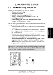
...: When lighted, the onboard LED indicates that the LED is turned OFF before handling components to avoid damaging them . 4. H/W SETUP Motherboard Settings TR-DLS TR-DLS Onboard LED LED1 ON Standby Power OFF Powered Off ASUS TR-DLS User's Manual 17 Install memory modules 3. Install a CPU terminator, if you install or remove any component, place the components on...
...: When lighted, the onboard LED indicates that the LED is turned OFF before handling components to avoid damaging them . 4. H/W SETUP Motherboard Settings TR-DLS TR-DLS Onboard LED LED1 ON Standby Power OFF Powered Off ASUS TR-DLS User's Manual 17 Install memory modules 3. Install a CPU terminator, if you install or remove any component, place the components on...

TR-DLS User Manual
Page 18
...motherboard and the function of the CPU external frequency (or bus clock). The figure below shows the location of the DIP switches on a DIP switch represents the ON or OFF position. Reserved 2. Reserved 5. CLKSW TR-DLS ON ON CPU 12345 100MHz 12345 133MHz TR-DLS ... CAUTION! Frequency Selection 2. Frequency Multiple 7. Frequency Selection 1. Frequency Multiple 6. Set the CPU frequency only to be stable. 18 ASUS TR-DLS User's Manual Frequency Selection 5. The bus clock multiplied by the the frequency multiple equals the CPU internal frequency (the advertised CPU...
...motherboard and the function of the CPU external frequency (or bus clock). The figure below shows the location of the DIP switches on a DIP switch represents the ON or OFF position. Reserved 2. Reserved 5. CLKSW TR-DLS ON ON CPU 12345 100MHz 12345 133MHz TR-DLS ... CAUTION! Frequency Selection 2. Frequency Multiple 7. Frequency Selection 1. Frequency Multiple 6. Set the CPU frequency only to be stable. 18 ASUS TR-DLS User's Manual Frequency Selection 5. The bus clock multiplied by the the frequency multiple equals the CPU internal frequency (the advertised CPU...

TR-DLS User Manual
Page 20
External Buzzer Setting (Switch 2) This switch allows you to enable the buzzer. TR-DLS ON 12345678 ON: Enable OFF: Disable TR-DLS External Buzzer Setting External Buzzer 20 ASUS TR-DLS User's Manual 3. HARDWARE SETUP The following figure shows the CPU core bus frequency settings for Pentium III... 6.0x 6.5x TR-DLS 7.0x 7.5x 8.0x 8.5x ON 12345678 ON 12345678 ON 12345678 ON 12345678 TR-DLS CPU (Tualatin) Frequency Multiple Selection 9.0x 9.5x 10.0x 10.5x ON 12345678 ON 12345678 ON 12345678 ON 12345678 11.0x 11.5x 12.0x 4.0x 3. H/W SETUP Motherboard Settings 3.
External Buzzer Setting (Switch 2) This switch allows you to enable the buzzer. TR-DLS ON 12345678 ON: Enable OFF: Disable TR-DLS External Buzzer Setting External Buzzer 20 ASUS TR-DLS User's Manual 3. HARDWARE SETUP The following figure shows the CPU core bus frequency settings for Pentium III... 6.0x 6.5x TR-DLS 7.0x 7.5x 8.0x 8.5x ON 12345678 ON 12345678 ON 12345678 ON 12345678 TR-DLS CPU (Tualatin) Frequency Multiple Selection 9.0x 9.5x 10.0x 10.5x ON 12345678 ON 12345678 ON 12345678 ON 12345678 11.0x 11.5x 12.0x 4.0x 3. H/W SETUP Motherboard Settings 3.
TR-DLS User Manual
Page 21
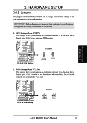
... jumper allows you to enable or disable the onboard VGA function. TR-DLS TR-DLS VGA Setting VGAEN 12 Enable (Default) 23 Disable ASUS TR-DLS User's Manual 21 Before changing any jumper setting, make sure to use SCSI devices. HARDWARE SETUP 3.4.2 Jumpers The jumpers on the motherboard allow you install a VGA card. IMPORTANT! Set to Enable (pins... to use the onboard VGA capability. Set to Enable (pins 1-2) if you wish to read the jumper descriptions and setting requirements in this section. 1. H/W SETUP Motherboard Settings 3.
... jumper allows you to enable or disable the onboard VGA function. TR-DLS TR-DLS VGA Setting VGAEN 12 Enable (Default) 23 Disable ASUS TR-DLS User's Manual 21 Before changing any jumper setting, make sure to use SCSI devices. HARDWARE SETUP 3.4.2 Jumpers The jumpers on the motherboard allow you install a VGA card. IMPORTANT! Set to Enable (pins... to use the onboard VGA capability. Set to Enable (pins 1-2) if you wish to read the jumper descriptions and setting requirements in this section. 1. H/W SETUP Motherboard Settings 3.

TR-DLS User Manual
Page 22
HARDWARE SETUP 3. To erase the RTC RAM: 1. Short the solder points for a few seconds. 4. H/W SETUP Motherboard Settings TR-DLS KBPWR 2 1 5V (Default) 3 2 5VSB TR-DLS Keyboard Power Setting 4. Remove the battery. 3. Keyboard Power Settings (3-pin KBPWR) This jumper allows you to enable or disable ... setting in CMOS. Turn OFF the computer and unplug the power cord. 2. TR-DLS CLRCMOS Short solder points to Clear CMOS PCI3 (32-bit, 33MHz 5V) PCI4 (32-bit, 33MHz 5V) TR-DLS Clear RTC RAM 22 ASUS TR-DLS User's Manual The RAM data that can clear the CMOS memory of date,...
HARDWARE SETUP 3. To erase the RTC RAM: 1. Short the solder points for a few seconds. 4. H/W SETUP Motherboard Settings TR-DLS KBPWR 2 1 5V (Default) 3 2 5VSB TR-DLS Keyboard Power Setting 4. Remove the battery. 3. Keyboard Power Settings (3-pin KBPWR) This jumper allows you to enable or disable ... setting in CMOS. Turn OFF the computer and unplug the power cord. 2. TR-DLS CLRCMOS Short solder points to Clear CMOS PCI3 (32-bit, 33MHz 5V) PCI4 (32-bit, 33MHz 5V) TR-DLS Clear RTC RAM 22 ASUS TR-DLS User's Manual The RAM data that can clear the CMOS memory of date,...
TR-DLS User Manual
Page 23
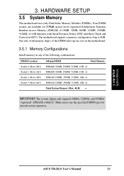
... 3.3Volt (power level) registered Synchronous Dynamic Random Access Memory (SDRAM) of 16MB, 32MB, 64MB, 128MB, 256MB, 512MB, or 1GB densities with ECC. H/W SETUP System Memory ASUS TR-DLS User's Manual 23 HARDWARE SETUP 3.5 System Memory This motherboard uses only Dual Inline Memory Modules (DIMMs). Four DIMM sockets are available for smooth system operation. 3.
... 3.3Volt (power level) registered Synchronous Dynamic Random Access Memory (SDRAM) of 16MB, 32MB, 64MB, 128MB, 256MB, 512MB, or 1GB densities with ECC. H/W SETUP System Memory ASUS TR-DLS User's Manual 23 HARDWARE SETUP 3.5 System Memory This motherboard uses only Dual Inline Memory Modules (DIMMs). Four DIMM sockets are available for smooth system operation. 3.
TR-DLS User Manual
Page 24
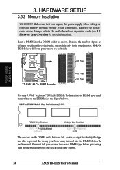
... damage to prevent the wrong type from being inserted into the DIMM socket as shown. Insert a DIMM into the DIMM slot on the motherboard. H/W SETUP System Memory The notches on either side of pins are different on the DIMM shifts between left, center, or right to... Make sure that you unplug the power supply when adding or removing memory modules or other system components. This motherboard supports four clock signals per DIMM. 24 ASUS TR-DLS User's Manual TR-DLS 88 Pins TR-DLS 168-Pin DIMM Sockets 60 Pins 20 Pins Use only 3.3Volt "registered" SDRAM DIMMs. To determine the DIMM...
... damage to prevent the wrong type from being inserted into the DIMM socket as shown. Insert a DIMM into the DIMM slot on the motherboard. H/W SETUP System Memory The notches on either side of pins are different on the DIMM shifts between left, center, or right to... Make sure that you unplug the power supply when adding or removing memory modules or other system components. This motherboard supports four clock signals per DIMM. 24 ASUS TR-DLS User's Manual TR-DLS 88 Pins TR-DLS 168-Pin DIMM Sockets 60 Pins 20 Pins Use only 3.3Volt "registered" SDRAM DIMMs. To determine the DIMM...

TR-DLS User Manual
Page 25
... unlocked processors) for Intel Pentium III Coppermine (256KB L2) and Tualatin (512KB L2) CPUs running up problems. 3. H/W SETUP CPU ASUS TR-DLS User's Manual 25 NOTE: Do not forget to set the correct Bus Frequency and Multiple (frequency multiple setting is installed... to correctly install them. HARDWARE SETUP 3.6 Central Processing Unit (CPU) The motherboard comes with a dual Socket 370 for the processor to avoid start-up to 1.53+GHz with the corresponding corner on the motherboard and the correct CPU and terminator orientation. 3. The following illustration shows the...
... unlocked processors) for Intel Pentium III Coppermine (256KB L2) and Tualatin (512KB L2) CPUs running up problems. 3. H/W SETUP CPU ASUS TR-DLS User's Manual 25 NOTE: Do not forget to set the correct Bus Frequency and Multiple (frequency multiple setting is installed... to correctly install them. HARDWARE SETUP 3.6 Central Processing Unit (CPU) The motherboard comes with a dual Socket 370 for the processor to avoid start-up to 1.53+GHz with the corresponding corner on the motherboard and the correct CPU and terminator orientation. 3. The following illustration shows the...

TR-DLS User Manual
Page 26
... the CPU terminator the same way as you push down the socket lever to a 90°-100° angle. 3. It will cause system damage! 26 ASUS TR-DLS User's Manual If the CPU does not fit completely, check its notched or marked corner matches the socket corner near the end of the lever... parallel to the documentation that the CPU is in one orientation. Unlock the socket by pressing the lever sideways then lifting it firmly on the motherboard. 2. 3. Locate the ZIF socket on the socket while you would install a CPU.
... the CPU terminator the same way as you push down the socket lever to a 90°-100° angle. 3. It will cause system damage! 26 ASUS TR-DLS User's Manual If the CPU does not fit completely, check its notched or marked corner matches the socket corner near the end of the lever... parallel to the documentation that the CPU is in one orientation. Unlock the socket by pressing the lever sideways then lifting it firmly on the motherboard. 2. 3. Locate the ZIF socket on the socket while you would install a CPU.

