
TR-DLS User Manual
Page 2
...the period of the manual revision number. Copyright © 2000 ASUSTeK COMPUTER INC. Product Name: ASUS TR-DLS Manual Revision: 3.00 E887 Release Date: November 2001 2 ASUS TR-DLS User's Manual ASUS PROVIDES THIS MANUAL "AS IS" WITHOUT WARRANTY OF ANY KIND, EITHER EXPRESS OR IMPLIED, INCLUDING ... alteration is defaced or missing. For previous or updated manuals, BIOS, drivers, or product release information, contact ASUS at http://www.asus.com.tw or through any means, except documentation kept by ASUS; ASUS ASSUMES NO RESPONSIBILITY OR LIABILITY FOR ANY ERRORS OR INACCURACIES THAT ...
...the period of the manual revision number. Copyright © 2000 ASUSTeK COMPUTER INC. Product Name: ASUS TR-DLS Manual Revision: 3.00 E887 Release Date: November 2001 2 ASUS TR-DLS User's Manual ASUS PROVIDES THIS MANUAL "AS IS" WITHOUT WARRANTY OF ANY KIND, EITHER EXPRESS OR IMPLIED, INCLUDING ... alteration is defaced or missing. For previous or updated manuals, BIOS, drivers, or product release information, contact ASUS at http://www.asus.com.tw or through any means, except documentation kept by ASUS; ASUS ASSUMES NO RESPONSIBILITY OR LIABILITY FOR ANY ERRORS OR INACCURACIES THAT ...

TR-DLS User Manual
Page 4
... 4.1.1 Upon First Use of the Computer System 41 4.1.2 Updating BIOS Procedures 43 4.2 BIOS Setup Program 45 4.2.1 BIOS Menu Bar 46 4.2.2 Legend Bar 46 4 ASUS TR-DLS User's Manual FEATURES 8 2.1 ASUS TR-DLS Motherboard 8 2.1.1 Specifications 8 2.1.2 Performance 10 2.1.3 Intelligence 11 2.2 TR-DLS Motherboard Components 12 2.2.1 Component Locations 13 3. HARDWARE SETUP 14 3.1 TR-DLS Motherboard Layout 14 3.2 Layout Contents 15 3.3 Hardware Setup Procedure 17 3.4 Motherboard Settings...
... 4.1.1 Upon First Use of the Computer System 41 4.1.2 Updating BIOS Procedures 43 4.2 BIOS Setup Program 45 4.2.1 BIOS Menu Bar 46 4.2.2 Legend Bar 46 4 ASUS TR-DLS User's Manual FEATURES 8 2.1 ASUS TR-DLS Motherboard 8 2.1.1 Specifications 8 2.1.2 Performance 10 2.1.3 Intelligence 11 2.2 TR-DLS Motherboard Components 12 2.2.1 Component Locations 13 3. HARDWARE SETUP 14 3.1 TR-DLS Motherboard Layout 14 3.2 Layout Contents 15 3.3 Hardware Setup Procedure 17 3.4 Motherboard Settings...
TR-DLS User Manual
Page 7
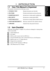
... Instructions on setting up the included software 6. SOFTWARE SETUP Instructions on setting up the BIOS 5. SOFTWARE REFERENCE Reference material for a 3.5" floppy disk drive (1) Support drivers and utilities (1) Socket 370 CPU Terminator (UMB type) (1) This Motherboard User's Manual ASUS TR-DLS User's Manual 7 INTRODUCTION Manual / Checklist 1. INTRODUCTION 1.1 How This Manual Is Organized This manual is...
... Instructions on setting up the included software 6. SOFTWARE SETUP Instructions on setting up the BIOS 5. SOFTWARE REFERENCE Reference material for a 3.5" floppy disk drive (1) Support drivers and utilities (1) Socket 370 CPU Terminator (UMB type) (1) This Motherboard User's Manual ASUS TR-DLS User's Manual 7 INTRODUCTION Manual / Checklist 1. INTRODUCTION 1.1 How This Manual Is Organized This manual is...
TR-DLS User Manual
Page 9
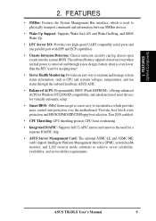
..., and HD/SCSI/MO/ZIP/CD/Floppy boot selection. ASUS TR-DLS User's Manual 9 The onboard battery supports detection even when normal power is removed and through the onboard hardware ASUS ASIC. • Enhanced ACPI: Programmable BIOS (Flash EEPROM), offering enhanced ACPI for Windows NT/2000/XP... compatibility, and autodetection of most devices for a separate IOAPIC chip. • ASUS Server Management Card: The optional ASMC-LE...
..., and HD/SCSI/MO/ZIP/CD/Floppy boot selection. ASUS TR-DLS User's Manual 9 The onboard battery supports detection even when normal power is removed and through the onboard hardware ASUS ASIC. • Enhanced ACPI: Programmable BIOS (Flash EEPROM), offering enhanced ACPI for Windows NT/2000/XP... compatibility, and autodetection of most devices for a separate IOAPIC chip. • ASUS Server Management Card: The optional ASMC-LE...
TR-DLS User Manual
Page 10
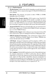
... connectors and descriptive icons make identification easy as Windows 98, must be ready around the clock, yet satisfy all ASUS smart series motherboards. ACPI provides more Energy Saving Features for SDG2.0 certification. The new SDG2.0 requirements for systems and... (Ultra160/320 SCSI cables have twisted pairs compared to flat ribbon cables used . • New Compliancy: Both the BIOS and hardware levels of 64bit PCI cards, supports up to (2) full 64-bit 66/33MHz PCI busses, and supports up...of ACPI, an ACPI-supported OS, such as required by PC '99. 10 ASUS TR-DLS User's Manual
... connectors and descriptive icons make identification easy as Windows 98, must be ready around the clock, yet satisfy all ASUS smart series motherboards. ACPI provides more Energy Saving Features for SDG2.0 certification. The new SDG2.0 requirements for systems and... (Ultra160/320 SCSI cables have twisted pairs compared to flat ribbon cables used . • New Compliancy: Both the BIOS and hardware levels of 64bit PCI cards, supports up to (2) full 64-bit 66/33MHz PCI busses, and supports up...of ACPI, an ACPI-supported OS, such as required by PC '99. 10 ASUS TR-DLS User's Manual
TR-DLS User Manual
Page 11
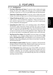
... and run large applications. Remote management response via remote diagnostics and troubleshooting still works even when the operating system has frozen. ASUS TR-DLS User's Manual 11 Regardless of the setting, pushing the power button for more information) button. All the fans are set ...Resources Alert: Today's server operating systems, such as Windows NT/2000/XP, require much more efficiently. • Dual Function Power Button: Through BIOS, the power button can be defined as the "Stand by" (a.k.a. Suggestions will enter the Soft-Off mode. • Remote Ring In (requires...
... and run large applications. Remote management response via remote diagnostics and troubleshooting still works even when the operating system has frozen. ASUS TR-DLS User's Manual 11 Regardless of the setting, pushing the power button for more information) button. All the fans are set ...Resources Alert: Today's server operating systems, such as Windows NT/2000/XP, require much more efficiently. • Dual Function Power Button: Through BIOS, the power button can be defined as the "Stand by" (a.k.a. Suggestions will enter the Soft-Off mode. • Remote Ring In (requires...
TR-DLS User Manual
Page 14
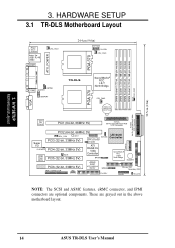
...I/O ATI CLRCMOS PCI4 (32-bit, 33MHz 5V) 4Mbit WOR Flash PCI5 (32-bit, 33MHz 5V) BIOS RAGE XL VGA Controller BPSMB ServerWorks ® RCC CSB5 South Bridge BUZZER ASUS ASIC PCI6 (32-bit, 33MHz 5V) with Hardware Monitor BPSMB Primary IDE1 Secondary IDE2 eRMC CONNECTOR IPMI ...FLOPPY PANEL HD_LED NOTE: The SCSI and ASMC features, eRMC connector, and IPMI connectors are grayed out in the above motherboard layout. 14 ASUS TR-DLS User's Manual...
...I/O ATI CLRCMOS PCI4 (32-bit, 33MHz 5V) 4Mbit WOR Flash PCI5 (32-bit, 33MHz 5V) BIOS RAGE XL VGA Controller BPSMB ServerWorks ® RCC CSB5 South Bridge BUZZER ASUS ASIC PCI6 (32-bit, 33MHz 5V) with Hardware Monitor BPSMB Primary IDE1 Secondary IDE2 eRMC CONNECTOR IPMI ...FLOPPY PANEL HD_LED NOTE: The SCSI and ASMC features, eRMC connector, and IPMI connectors are grayed out in the above motherboard layout. 14 ASUS TR-DLS User's Manual...
TR-DLS User Manual
Page 17
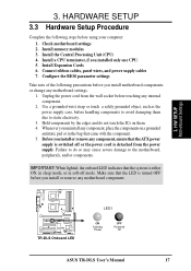
... or touch a safely grounded object, such as the power supply case, before using your computer: 1. H/W SETUP Motherboard Settings TR-DLS TR-DLS Onboard LED LED1 ON Standby Power OFF Powered Off ASUS TR-DLS User's Manual 17 Configure the BIOS parameter settings Take note of the following steps before handling components to the motherboard, peripherals, and/or components...
... or touch a safely grounded object, such as the power supply case, before using your computer: 1. H/W SETUP Motherboard Settings TR-DLS TR-DLS Onboard LED LED1 ON Standby Power OFF Powered Off ASUS TR-DLS User's Manual 17 Configure the BIOS parameter settings Take note of the following steps before handling components to the motherboard, peripherals, and/or components...

TR-DLS User Manual
Page 22
... passwords, is powered by erasing the CMOS Real Time Clock (RTC) RAM. Re-install the battery. 5. Plug the power cord and turn ON the computer. 6. TR-DLS CLRCMOS Short solder points to re-enter CMOS data. Clear RTC RAM (CLRCMOS) These two solder points allow you to clear the RTC RAM in... computer and unplug the power cord. 2. Hold down the key during the boot process and enter BIOS setup to Clear CMOS PCI3 (32-bit, 33MHz 5V) PCI4 (32-bit, 33MHz 5V) TR-DLS Clear RTC RAM 22 ASUS TR-DLS User's Manual The RAM data that can clear the CMOS memory of date, time, and system...
... passwords, is powered by erasing the CMOS Real Time Clock (RTC) RAM. Re-install the battery. 5. Plug the power cord and turn ON the computer. 6. TR-DLS CLRCMOS Short solder points to re-enter CMOS data. Clear RTC RAM (CLRCMOS) These two solder points allow you to clear the RTC RAM in... computer and unplug the power cord. 2. Hold down the key during the boot process and enter BIOS setup to Clear CMOS PCI3 (32-bit, 33MHz 5V) PCI4 (32-bit, 33MHz 5V) TR-DLS Clear RTC RAM 22 ASUS TR-DLS User's Manual The RAM data that can clear the CMOS memory of date, time, and system...
TR-DLS User Manual
Page 27
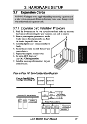
...-5 PCI-6 ATI RageXL 32-bit 32-bit 32-bit 32-bit Intel 82550 ASUS TR-DLS User's Manual 27 Failure to do so may cause severe damage to both your expansion card. Replace the computer system's cover. 6. Set up the BIOS if necessary (see 4.4.3 PCI Configuration) 7. Keep the bracket for your computer system's cover...
...-5 PCI-6 ATI RageXL 32-bit 32-bit 32-bit 32-bit Intel 82550 ASUS TR-DLS User's Manual 27 Failure to do so may cause severe damage to both your expansion card. Replace the computer system's cover. 6. Set up the BIOS if necessary (see 4.4.3 PCI Configuration) 7. Keep the bracket for your computer system's cover...
TR-DLS User Manual
Page 30
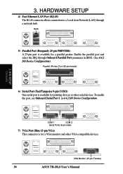
... Onboard Parallel Port parameter in 4.4.2 I /O Device Configuration). Parallel (Printer) Port (25-pin female) 3. VGA Monitor (15-pin Female) 30 ASUS TR-DLS User's Manual To enable the port, see Onboard Serial Port 1 in BIOS. (See 4.4.2 I /O Device Configuration. RJ45 5) Parallel Port (Burgundy 25-pin PRINTER) A 25-pin port is available for pointing devices or other...
... Onboard Parallel Port parameter in 4.4.2 I /O Device Configuration). Parallel (Printer) Port (25-pin female) 3. VGA Monitor (15-pin Female) 30 ASUS TR-DLS User's Manual To enable the port, see Onboard Serial Port 1 in BIOS. (See 4.4.2 I /O Device Configuration. RJ45 5) Parallel Port (Burgundy 25-pin PRINTER) A 25-pin port is available for pointing devices or other...
TR-DLS User Manual
Page 31
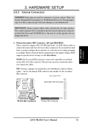
... hard disks, you connect the cables. H/W SETUP Connectors 3. Refer to your motherboard. PIN 1 Secondary IDE Connector TR-DLS TR-DLS IDE Connectors PIN 1 Primary IDE Connector ASUS TR-DLS User's Manual 31 Use IDE ribbon cables to connect the master and slave devices to these connector pins will cause ... closest to be both Masters with two ribbon cables - one for the primary IDE connector and another for the secondary IDE connector. BIOS supports specific device bootup (see 4.6. Boot Menu). ribbon cable to match the covered hole on the connector. 3. IMPORTANT: Always connect...
... hard disks, you connect the cables. H/W SETUP Connectors 3. Refer to your motherboard. PIN 1 Secondary IDE Connector TR-DLS TR-DLS IDE Connectors PIN 1 Primary IDE Connector ASUS TR-DLS User's Manual 31 Use IDE ribbon cables to connect the master and slave devices to these connector pins will cause ... closest to be both Masters with two ribbon cables - one for the primary IDE connector and another for the secondary IDE connector. BIOS supports specific device bootup (see 4.6. Boot Menu). ribbon cable to match the covered hole on the connector. 3. IMPORTANT: Always connect...
TR-DLS User Manual
Page 33
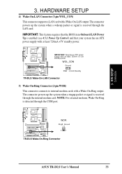
H/W SETUP Connectors 3. TR-DLS IMPORTANT: Requires an ATX power supply with at least 720mA +5V standby power. The connector powers up the system when a wakeup packet or signal is ... connects to internal modem cards with a Wake-On-LAN output. IMPORTANT: This feature requires that the BIOS item Onboard LAN Power Up is detected through the internal modem card. TR-DLS WOR Ring# Ground 2 1 TR-DLS Wake-On-Ring Connector ASUS TR-DLS User's Manual 33 HARDWARE SETUP 4) Wake-On-LAN Connector (3-pin WOL_CON) This connector supports a LAN...
H/W SETUP Connectors 3. TR-DLS IMPORTANT: Requires an ATX power supply with at least 720mA +5V standby power. The connector powers up the system when a wakeup packet or signal is ... connects to internal modem cards with a Wake-On-LAN output. IMPORTANT: This feature requires that the BIOS item Onboard LAN Power Up is detected through the internal modem card. TR-DLS WOR Ring# Ground 2 1 TR-DLS Wake-On-Ring Connector ASUS TR-DLS User's Manual 33 HARDWARE SETUP 4) Wake-On-LAN Connector (3-pin WOL_CON) This connector supports a LAN...
TR-DLS User Manual
Page 38
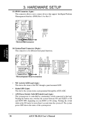
...+ Status LED - Pushing the button once switches the system between ON and SLEEP or ON and SOFT OFF, depending on your BIOS or OS setting. 3. H/W SETUP Connectors TR-DLS IPMI Connector 14) System Panel Connector (20-pin ) This connector is controlled by a momentary switch connected to connect devices that ... Speaker 18 & 19 HDD Access LED * Shared • NIC Activity LED Lead (2-pin) This shows the status of the system power. 38 ASUS TR-DLS User's Manual Power LED + NIC activity LED- HARDWARE SETUP 13) IPMI Connector (4-pin ) This connector allows you to this lead. Power LED...
...+ Status LED - Pushing the button once switches the system between ON and SLEEP or ON and SOFT OFF, depending on your BIOS or OS setting. 3. H/W SETUP Connectors TR-DLS IPMI Connector 14) System Panel Connector (20-pin ) This connector is controlled by a momentary switch connected to connect devices that ... Speaker 18 & 19 HDD Access LED * Shared • NIC Activity LED Lead (2-pin) This shows the status of the system power. 38 ASUS TR-DLS User's Manual Power LED + NIC activity LED- HARDWARE SETUP 13) IPMI Connector (4-pin ) This connector allows you to this lead. Power LED...
TR-DLS User Manual
Page 40
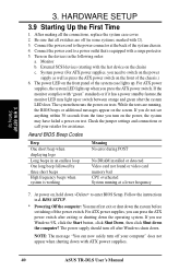
... runs the power-on the screen. Check the jumper settings and connections or call your computer" does not appear when shutting down the computer? BIOS SETUP. * Powering Off the computer: You must first exit or shut down . Be sure that is working Meaning No error during POST No...system LED does. 3. Award BIOS Beep Codes Beep One short beep when displaying logo Long beeps in 4. Follow the instructions in an endless loop One long beep followed by three short beeps High frequency beeps when system is equipped with ATX power supplies. 40 ASUS TR-DLS User's Manual System power (For...
... runs the power-on the screen. Check the jumper settings and connections or call your computer" does not appear when shutting down the computer? BIOS SETUP. * Powering Off the computer: You must first exit or shut down . Be sure that is working Meaning No error during POST No...system LED does. 3. Award BIOS Beep Codes Beep One short beep when displaying logo Long beeps in 4. Follow the instructions in an endless loop One long beep followed by three short beeps High frequency beeps when system is equipped with ATX power supplies. 40 ASUS TR-DLS User's Manual System power (For...
TR-DLS User Manual
Page 41
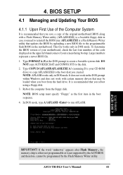
...either not programmable or is recommended that may be programmed by uploading a new BIOS file to the programmable flash ROM on the upper left-hand corner of the code displayed on the motherboard. ASUS TR-DLS User's Manual 41 Type COPY D:\AFLASH\AFLASH.EXE A:\ (assuming D is... recommended that updates the BIOS by the Flash Memory Writer utility. NOTE: BIOS setup must specify "Floppy" as the first item in DOS mode. BIOS SETUP Updating BIOS IMPORTANT! It is your screen...
...either not programmable or is recommended that may be programmed by uploading a new BIOS file to the programmable flash ROM on the upper left-hand corner of the code displayed on the motherboard. ASUS TR-DLS User's Manual 41 Type COPY D:\AFLASH\AFLASH.EXE A:\ (assuming D is... recommended that updates the BIOS by the Flash Memory Writer utility. NOTE: BIOS setup must specify "Floppy" as the first item in DOS mode. BIOS SETUP Updating BIOS IMPORTANT! It is your screen...
TR-DLS User Manual
Page 42
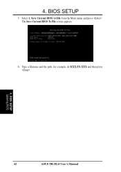
The Save Current BIOS To File screen appears. 6. Select 1. Type a filename and the path, for example, A:\XXX-XX.XXX and then press . 4. 4. Save Current BIOS to File from the Main menu and press . BIOS SETUP Updating BIOS 42 ASUS TR-DLS User's Manual BIOS SETUP 5.
The Save Current BIOS To File screen appears. 6. Select 1. Type a filename and the path, for example, A:\XXX-XX.XXX and then press . 4. 4. Save Current BIOS to File from the Main menu and press . BIOS SETUP Updating BIOS 42 ASUS TR-DLS User's Manual BIOS SETUP 5.

TR-DLS User Manual
Page 43
... problems with the motherboard and you have problems with the motherboard! 1. Update the BIOS only if you know that the new BIOS revision will solve your new BIOS and the path, for details) and save to start the update. 4. The Update BIOS Including Boot Block and ESCD screen appears. 5. 4. BIOS SETUP Updating BIOS ASUS TR-DLS User's Manual 43
... problems with the motherboard and you have problems with the motherboard! 1. Update the BIOS only if you know that the new BIOS revision will solve your new BIOS and the path, for details) and save to start the update. 4. The Update BIOS Including Boot Block and ESCD screen appears. 5. 4. BIOS SETUP Updating BIOS ASUS TR-DLS User's Manual 43
TR-DLS User Manual
Page 44
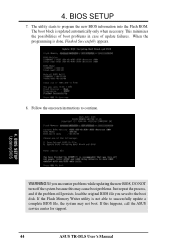
...4. This minimizes the possibilities of boot problems in case of update failures. When the programming is not able to the boot disk. BIOS SETUP Updating BIOS WARNING! If this may not boot. If the Flash Memory Writer utility is done, Flashed Successfully appears. 8. 4. If you saved..., and if the problem still persists, load the original BIOS file you encounter problems while updating the new BIOS, DO NOT turn off the system because this happens, call the ASUS service center for support. 44 ASUS TR-DLS User's Manual The boot block is updated automatically only when...
...4. This minimizes the possibilities of boot problems in case of update failures. When the programming is not able to the boot disk. BIOS SETUP Updating BIOS WARNING! If this may not boot. If the Flash Memory Writer utility is done, Flashed Successfully appears. 8. 4. If you saved..., and if the problem still persists, load the original BIOS file you encounter problems while updating the new BIOS, DO NOT turn off the system because this happens, call the ASUS service center for support. 44 ASUS TR-DLS User's Manual The boot block is updated automatically only when...
TR-DLS User Manual
Page 45
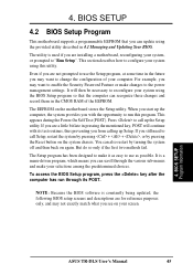
... using the provided utility described in the CMOS RAM of your system using this program. BIOS SETUP Program Information ASUS TR-DLS User's Manual 45 4. For example, you may not exactly match what you with its POST. To access the BIOS Setup program, press the key after the computer has run this utility. NOTE: Because...
... using the provided utility described in the CMOS RAM of your system using this program. BIOS SETUP Program Information ASUS TR-DLS User's Manual 45 4. For example, you may not exactly match what you with its POST. To access the BIOS Setup program, press the key after the computer has run this utility. NOTE: Because...
