

TR-DLS User Manual
Page 4
... 3.5.1 Memory Configurations 23 3.5.2 Memory Installation 24 3.6 Central Processing Unit (CPU 25 3.6.1 Installing the CPU and Terminator 26 3.7 Expansion Cards 27 3.7.1 Expansion Card Installation Procedure 27 3.7.2 Assigning IRQs for Expansion Cards 28 3.8 Connectors 29 3.8.1 External Connectors 29 3.8.2 Internal Connectors 31 3.9 Starting Up the First Time 40 4. FEATURES 8 2.1 ASUS TR-DLS Motherboard 8 2.1.1 Specifications 8 2.1.2 Performance 10 2.1.3 Intelligence 11 2.2 TR-DLS...
... 3.5.1 Memory Configurations 23 3.5.2 Memory Installation 24 3.6 Central Processing Unit (CPU 25 3.6.1 Installing the CPU and Terminator 26 3.7 Expansion Cards 27 3.7.1 Expansion Card Installation Procedure 27 3.7.2 Assigning IRQs for Expansion Cards 28 3.8 Connectors 29 3.8.1 External Connectors 29 3.8.2 Internal Connectors 31 3.9 Starting Up the First Time 40 4. FEATURES 8 2.1 ASUS TR-DLS Motherboard 8 2.1.1 Specifications 8 2.1.2 Performance 10 2.1.3 Intelligence 11 2.2 TR-DLS...
TR-DLS User Manual
Page 8
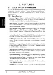
...Dual Inline Memory Module (DIMM) sockets that support up to 4GB of the same type and speed are installed. • ServerWorks LE-T 3.0 Chipset: Features the ServerWorks® RCC Champion LE-T North Bridge and RCC Champion South Bridge (CSB5). FEATURES 2.1 ASUS TR-DLS Motherboard The ASUS TR-DLS motherboard is designed for additional peripherals 8 ASUS TR-DLS User's ... support four IDE devices on two channels. Powered by dual Intel® Pentium® III Coppermine and Tualatin™ processors, the TR-DLS efficiently complies with two connectors that require flexible configurations.
...Dual Inline Memory Module (DIMM) sockets that support up to 4GB of the same type and speed are installed. • ServerWorks LE-T 3.0 Chipset: Features the ServerWorks® RCC Champion LE-T North Bridge and RCC Champion South Bridge (CSB5). FEATURES 2.1 ASUS TR-DLS Motherboard The ASUS TR-DLS motherboard is designed for additional peripherals 8 ASUS TR-DLS User's ... support four IDE devices on two channels. Powered by dual Intel® Pentium® III Coppermine and Tualatin™ processors, the TR-DLS efficiently complies with two connectors that require flexible configurations.
TR-DLS User Manual
Page 10
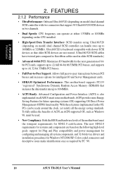
... for intelligent IO and Server Management cards. • SDRAM Optimized Performance: This motherboard supports PC133 "registered" Synchronous Dynamic Random Access Memory (SDRAM) that support 30 Ultra160/320 SCSI devices in older SCSI standards.) • Advanced 64-bit PCI: Maximizes IO bandwidth ...; New Compliancy: Both the BIOS and hardware levels of ACPI, an ACPI-supported OS, such as required by PC '99. 10 ASUS TR-DLS User's Manual FEATURES 2.1.2 Performance • UltraPerformance: Onboard Ultra160/320 (depending on model) dual channel SCSI controller with slower SCSI devices ...
... for intelligent IO and Server Management cards. • SDRAM Optimized Performance: This motherboard supports PC133 "registered" Synchronous Dynamic Random Access Memory (SDRAM) that support 30 Ultra160/320 SCSI devices in older SCSI standards.) • Advanced 64-bit PCI: Maximizes IO bandwidth ...; New Compliancy: Both the BIOS and hardware levels of ACPI, an ACPI-supported OS, such as required by PC '99. 10 ASUS TR-DLS User's Manual FEATURES 2.1.2 Performance • UltraPerformance: Onboard Ultra160/320 (depending on model) dual channel SCSI controller with slower SCSI devices ...
TR-DLS User Manual
Page 11
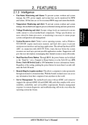
... memory and hard drive space to prevent possible application crashes. Suspend or Sleep) button or as Windows NT/2000/XP, require much more efficiently. • Dual Function Power Button: Through BIOS, the power button can be defined as the "Stand by" (a.k.a. ASUS TR-DLS User... components. Remote management response via remote diagnostics and troubleshooting still works even when the operating system has frozen. 2. The onboard hardware ASUS ASIC, in 3.8 Connectors for more than 4 seconds will give the user information on -hand, users can access any information from...
... memory and hard drive space to prevent possible application crashes. Suspend or Sleep) button or as Windows NT/2000/XP, require much more efficiently. • Dual Function Power Button: Through BIOS, the power button can be defined as the "Stand by" (a.k.a. ASUS TR-DLS User... components. Remote management response via remote diagnostics and troubleshooting still works even when the operating system has frozen. 2. The onboard hardware ASUS ASIC, in 3.8 Connectors for more than 4 seconds will give the user information on -hand, users can access any information from...
TR-DLS User Manual
Page 12
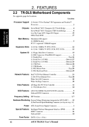
...TR-DLS Motherboard Components See opposite page for Pentium® III Coppermine and Tualatin™ Processors 2 Chipsets ServerWorks® RCC Champion LE-T North Bridge 4 ServerWorks® RCC Champion CSB5 South Bridge 8 Low Pin Count (LPC) Super-I/O Chipset 19 4Mbit Flash ROM 17 Main Memory... in ASUS ASIC) ....... 12 (4) Fan Power & Speed Monitoring Connectors (see layout on p. 14) Power ATX 24-pin Power Supply Connector 1 Special Features Intelligent Platform Management Interface (IPMI 15 eRMC Connector 16 Onboard LED 14 Form Factor EATX (12 in .) 12 ASUS TR-DLS User's...
...TR-DLS Motherboard Components See opposite page for Pentium® III Coppermine and Tualatin™ Processors 2 Chipsets ServerWorks® RCC Champion LE-T North Bridge 4 ServerWorks® RCC Champion CSB5 South Bridge 8 Low Pin Count (LPC) Super-I/O Chipset 19 4Mbit Flash ROM 17 Main Memory... in ASUS ASIC) ....... 12 (4) Fan Power & Speed Monitoring Connectors (see layout on p. 14) Power ATX 24-pin Power Supply Connector 1 Special Features Intelligent Platform Management Interface (IPMI 15 eRMC Connector 16 Onboard LED 14 Form Factor EATX (12 in .) 12 ASUS TR-DLS User's...
TR-DLS User Manual
Page 15
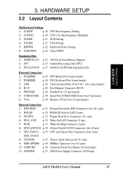
... p. 21 SCSI Setting 4) VGAEN p. 21 VGA Setting 5) KBPWR p. 22 Keyboard Power Setting 6) CLRCMOS p. 22 Clear CMOS Expansion Slots 1) DIMM 0/1/2/3 2) CPU 3) PCI1/2/3/4/5/6 p. 23 168-Pin System Memory Support p. 25 Central Processing Unit (CPU) p. 27 64-bit/32-bit PCI Bus Expansion Slot External Connectors 1) PS2KBMS p. 29 PS/2 Mouse Port (6-pin female) 2) PS2KBMS... p. 36 SMBus Connectors (two 6-1 pins) 10 USBPORT p. 36 Universal Serial Port Header (10-1pin male) 11) ATXPWR p. 37 ATX Power Supply Connector (20/24-pin) ASUS TR-DLS User's Manual 15 3.
... p. 21 SCSI Setting 4) VGAEN p. 21 VGA Setting 5) KBPWR p. 22 Keyboard Power Setting 6) CLRCMOS p. 22 Clear CMOS Expansion Slots 1) DIMM 0/1/2/3 2) CPU 3) PCI1/2/3/4/5/6 p. 23 168-Pin System Memory Support p. 25 Central Processing Unit (CPU) p. 27 64-bit/32-bit PCI Bus Expansion Slot External Connectors 1) PS2KBMS p. 29 PS/2 Mouse Port (6-pin female) 2) PS2KBMS... p. 36 SMBus Connectors (two 6-1 pins) 10 USBPORT p. 36 Universal Serial Port Header (10-1pin male) 11) ATXPWR p. 37 ATX Power Supply Connector (20/24-pin) ASUS TR-DLS User's Manual 15 3.
TR-DLS User Manual
Page 17
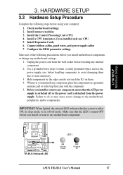
3. Install memory modules 3. Connect ribbon cables, panel wires, and power supply cables 7. Failure to do not touch the ICs on a grounded antistatic pad or in the bag ... note of the following steps before touching any component, place the components on them due to static electricity. 3. H/W SETUP Motherboard Settings TR-DLS TR-DLS Onboard LED LED1 ON Standby Power OFF Powered Off ASUS TR-DLS User's Manual 17 Install the Central Processing Unit (CPU) 4. Unplug the power cord from the power supply. Check motherboard settings...
3. Install memory modules 3. Connect ribbon cables, panel wires, and power supply cables 7. Failure to do not touch the ICs on a grounded antistatic pad or in the bag ... note of the following steps before touching any component, place the components on them due to static electricity. 3. H/W SETUP Motherboard Settings TR-DLS TR-DLS Onboard LED LED1 ON Standby Power OFF Powered Off ASUS TR-DLS User's Manual 17 Install the Central Processing Unit (CPU) 4. Unplug the power cord from the power supply. Check motherboard settings...

TR-DLS User Manual
Page 22
... Settings (3-pin KBPWR) This jumper allows you to re-enter CMOS data. H/W SETUP Motherboard Settings TR-DLS KBPWR 2 1 5V (Default) 3 2 5VSB TR-DLS Keyboard Power Setting 4. The RAM data that can clear the CMOS memory of date, time, and system setup parameters by the onboard button cell battery. HARDWARE SETUP 3. This... the keyboard wake-up the computer when you to Clear CMOS PCI3 (32-bit, 33MHz 5V) PCI4 (32-bit, 33MHz 5V) TR-DLS Clear RTC RAM 22 ASUS TR-DLS User's Manual Set this jumper to pins 2-3 (5VSB) if you wish to wake up feature. You can supply at least 1A...
... Settings (3-pin KBPWR) This jumper allows you to re-enter CMOS data. H/W SETUP Motherboard Settings TR-DLS KBPWR 2 1 5V (Default) 3 2 5VSB TR-DLS Keyboard Power Setting 4. The RAM data that can clear the CMOS memory of date, time, and system setup parameters by the onboard button cell battery. HARDWARE SETUP 3. This... the keyboard wake-up the computer when you to Clear CMOS PCI3 (32-bit, 33MHz 5V) PCI4 (32-bit, 33MHz 5V) TR-DLS Clear RTC RAM 22 ASUS TR-DLS User's Manual Set this jumper to pins 2-3 (5VSB) if you wish to wake up feature. You can supply at least 1A...
TR-DLS User Manual
Page 23
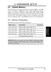
...the specified DIMM types for 3.3Volt (power level) registered Synchronous Dynamic Random Access Memory (SDRAM) of 16MB, 32MB, 64MB, 128MB, 256MB, 512MB, or 1GB densities with memory chips) of the following combinations: DIMM Location Socket 0 (Rows 0&1) Socket 1...Memory (Max. 4GB) = IMPORTANT: The system chipset only supports 64Mbit, 128Mbit, and 256Mbit "registered" SDRAMs with ECC. One side (with Serial Presence Detect (SPD) and Error Check and Correction (ECC). Four DIMM sockets are available for smooth system operation. 3. Make sure to 4GB. H/W SETUP System Memory ASUS TR-DLS...
...the specified DIMM types for 3.3Volt (power level) registered Synchronous Dynamic Random Access Memory (SDRAM) of 16MB, 32MB, 64MB, 128MB, 256MB, 512MB, or 1GB densities with memory chips) of the following combinations: DIMM Location Socket 0 (Rows 0&1) Socket 1...Memory (Max. 4GB) = IMPORTANT: The system chipset only supports 64Mbit, 128Mbit, and 256Mbit "registered" SDRAMs with ECC. One side (with Serial Presence Detect (SPD) and Error Check and Correction (ECC). Four DIMM sockets are available for smooth system operation. 3. Make sure to 4GB. H/W SETUP System Memory ASUS TR-DLS...
TR-DLS User Manual
Page 24
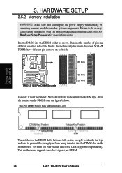
...only fits in one direction. 3. HARDWARE SETUP 3.5.2 Memory Installation WARNING! Make sure that you unplug the power supply when adding or removing memory modules or other system components. This motherboard supports four clock signals per DIMM. 24 ASUS TR-DLS User's Manual Failure to do so may cause severe... damage to prevent the wrong type from being inserted into the DIMM socket as shown. Insert a DIMM into the DIMM slot on the motherboard. H/W SETUP System Memory The notches on the DIMMs...
...only fits in one direction. 3. HARDWARE SETUP 3.5.2 Memory Installation WARNING! Make sure that you unplug the power supply when adding or removing memory modules or other system components. This motherboard supports four clock signals per DIMM. 24 ASUS TR-DLS User's Manual Failure to do so may cause severe... damage to prevent the wrong type from being inserted into the DIMM socket as shown. Insert a DIMM into the DIMM slot on the motherboard. H/W SETUP System Memory The notches on the DIMMs...
TR-DLS User Manual
Page 40
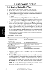
...devices in an endless loop One long beep followed by three short beeps High frequency beeps when system is equipped with ATX power supplies. 40 ASUS TR-DLS User's Manual The power LED on , hold down . While the tests are off (in 4. Award BIOS Beep Codes Beep One short ...surge protector. 5. Be sure that is working Meaning No error during POST No DRAM installed or detected Video card not found or video card memory bad CPU overheated System running , the BIOS beeps or additional messages appear on tests. Check the jumper settings and connections or call your computer...
...devices in an endless loop One long beep followed by three short beeps High frequency beeps when system is equipped with ATX power supplies. 40 ASUS TR-DLS User's Manual The power LED on , hold down . While the tests are off (in 4. Award BIOS Beep Codes Beep One short ...surge protector. 5. Be sure that is working Meaning No error during POST No DRAM installed or detected Video card not found or video card memory bad CPU overheated System running , the BIOS beeps or additional messages appear on tests. Check the jumper settings and connections or call your computer...
TR-DLS User Manual
Page 41
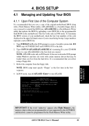
...\AFLASH.EXE A:\ (assuming D is a Flash Memory Writer utility that you created. Larger numbers represent a newer BIOS file. 1. Reboot the computer from the hard drive. BIOS SETUP Updating BIOS IMPORTANT! AFLASH.EXE is your screen during bootup. ASUS TR-DLS User's Manual 41 This file works only in... of your CD-ROM drive) to copy AFLASH.EXE to reinstall the BIOS later. If the word "unknown" appears after Flash Memory:, the memory chip is either not programmable or is recommended that may be programmed by uploading a new BIOS file to create a bootable system disk...
...\AFLASH.EXE A:\ (assuming D is a Flash Memory Writer utility that you created. Larger numbers represent a newer BIOS file. 1. Reboot the computer from the hard drive. BIOS SETUP Updating BIOS IMPORTANT! AFLASH.EXE is your screen during bootup. ASUS TR-DLS User's Manual 41 This file works only in... of your CD-ROM drive) to copy AFLASH.EXE to reinstall the BIOS later. If the word "unknown" appears after Flash Memory:, the memory chip is either not programmable or is recommended that may be programmed by uploading a new BIOS file to create a bootable system disk...
TR-DLS User Manual
Page 44
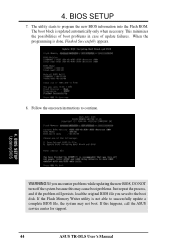
If the Flash Memory Writer utility is done, Flashed Successfully appears. 8. If this may not boot. 4. Follow the onscreen instructions to program the new BIOS information into the Flash ... of update failures. If you encounter problems while updating the new BIOS, DO NOT turn off the system because this happens, call the ASUS service center for support. 44 ASUS TR-DLS User's Manual The utility starts to continue. 4. BIOS SETUP Updating BIOS WARNING! When the programming is not able to successfully update a complete...
If the Flash Memory Writer utility is done, Flashed Successfully appears. 8. If this may not boot. 4. Follow the onscreen instructions to program the new BIOS information into the Flash ... of update failures. If you encounter problems while updating the new BIOS, DO NOT turn off the system because this happens, call the ASUS service center for support. 44 ASUS TR-DLS User's Manual The utility starts to continue. 4. BIOS SETUP Updating BIOS WARNING! When the programming is not able to successfully update a complete...
TR-DLS User Manual
Page 54
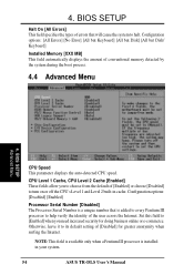
...Disk/ Keyboard] Installed Memory [XXX MB] This field automatically displays the amount of [Disabled] for doing business online or e-commerce. Set this field to [Enabled] when you to turn on or off the CPU's Level 1 and Level 2 built-in your system. 54 ASUS TR-DLS User's Manual NOTE:... This field is available only when a Pentium III processor is a unique number that will cause the system to its default setting of conventional memory detected by the system during the boot process. 4.4 Advanced Menu...
...Disk/ Keyboard] Installed Memory [XXX MB] This field automatically displays the amount of [Disabled] for doing business online or e-commerce. Set this field to [Enabled] when you to turn on or off the CPU's Level 1 and Level 2 built-in your system. 54 ASUS TR-DLS User's Manual NOTE:... This field is available only when a Pentium III processor is a unique number that will cause the system to its default setting of conventional memory detected by the system during the boot process. 4.4 Advanced Menu...
TR-DLS User Manual
Page 55
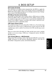
...] 4. Configuration options: [Disabled] [Enabled] [Auto] OS/2 Onboard Memory > 64M [Disabled] When using a USB device. In the default position of greater than 64MB, you set this on all processors during system bootup. The default setting [Auto] allows the system to [Enabled]; BIOS SETUP Advanced Menu ASUS TR-DLS User's Manual 55 IRQ12 will load the...
...] 4. Configuration options: [Disabled] [Enabled] [Auto] OS/2 Onboard Memory > 64M [Disabled] When using a USB device. In the default position of greater than 64MB, you set this on all processors during system bootup. The default setting [Auto] allows the system to [Enabled]; BIOS SETUP Advanced Menu ASUS TR-DLS User's Manual 55 IRQ12 will load the...
TR-DLS User Manual
Page 56
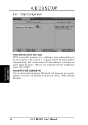
...] [USWC] Onboard PCI IDE Enable [Both] You can greatly improve the display speed by caching the display data. BIOS SETUP Chip Configuration 56 ASUS TR-DLS User's Manual 4. Configuration options: [Both] [Primary] [Disabled] 4. BIOS SETUP 4.4.1 Chip Configuration Video Memory Cache Mode [UC] USWC (uncacheable, speculative write combining) is a new cache technology for the video...
...] [USWC] Onboard PCI IDE Enable [Both] You can greatly improve the display speed by caching the display data. BIOS SETUP Chip Configuration 56 ASUS TR-DLS User's Manual 4. Configuration options: [Both] [Primary] [Disabled] 4. BIOS SETUP 4.4.1 Chip Configuration Video Memory Cache Mode [UC] USWC (uncacheable, speculative write combining) is a new cache technology for the video...
TR-DLS User Manual
Page 67
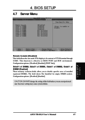
Configuration options: [Disabled] [Enabled] [POST Only] Side0/1 of DIMM0, Side0/1 of DIMM1, Side0/1 of DIMM2, Side0/1 of DIMM3 [Enabled] These memory isolation fields allow you are an experienced user. ASUS TR-DLS User's Manual 67 4. Incorrect setting may cause system failure. This function is effective at BIOS POST and DOS environment. BIOS SETUP Boot Menu...
Configuration options: [Disabled] [Enabled] [POST Only] Side0/1 of DIMM0, Side0/1 of DIMM1, Side0/1 of DIMM2, Side0/1 of DIMM3 [Enabled] These memory isolation fields allow you are an experienced user. ASUS TR-DLS User's Manual 67 4. Incorrect setting may cause system failure. This function is effective at BIOS POST and DOS environment. BIOS SETUP Boot Menu...

TR-DLS User Manual
Page 92
...The Loading Driver Update Software screen appears, along with a progress bar that shows the percentage of drivers that are read into memory and survive long enough for the system to successfully boot to boot your system. IMPORTANT: Do not remove the Solaris Device Configuration...Configuration Assistant Diskette. When all the Solaris Driver ITU diskettes you want are installed. 9. Press F2_Continue. Driver Installation SUN Solaris 7 Server 92 ASUS TR-DLS User's Manual Repeat Step 4 through Step 8 until you see the following message displayed in a dialog box: "If you want to ...
...The Loading Driver Update Software screen appears, along with a progress bar that shows the percentage of drivers that are read into memory and survive long enough for the system to successfully boot to boot your system. IMPORTANT: Do not remove the Solaris Device Configuration...Configuration Assistant Diskette. When all the Solaris Driver ITU diskettes you want are installed. 9. Press F2_Continue. Driver Installation SUN Solaris 7 Server 92 ASUS TR-DLS User's Manual Repeat Step 4 through Step 8 until you see the following message displayed in a dialog box: "If you want to ...