
TR-DLS User Manual
Page 7
...1.2 Item Checklist Check that your retailer. (1) ASUS Motherboard (1) I/O Shield (1) Ribbon cable for master and slave IDE drives (1) 68-pin LVD SCSI ribbon cable for Ultra160/320 devices with Terminator (1)... Ribbon cable for the included software 7. INTRODUCTION Manual / Checklist 1. FEATURES Production information and specifications 3. SOFTWARE REFERENCE Reference material for a 3.5" floppy disk drive (1) Support drivers and utilities (1) Socket 370 CPU Terminator (UMB type) (1) This Motherboard User's Manual ASUS TR-DLS...
...1.2 Item Checklist Check that your retailer. (1) ASUS Motherboard (1) I/O Shield (1) Ribbon cable for master and slave IDE drives (1) 68-pin LVD SCSI ribbon cable for Ultra160/320 devices with Terminator (1)... Ribbon cable for the included software 7. INTRODUCTION Manual / Checklist 1. FEATURES Production information and specifications 3. SOFTWARE REFERENCE Reference material for a 3.5" floppy disk drive (1) Support drivers and utilities (1) Socket 370 CPU Terminator (UMB type) (1) This Motherboard User's Manual ASUS TR-DLS...
TR-DLS User Manual
Page 8
...Bridge and RCC Champion South Bridge (CSB5). FEATURES Specifications 2. FEATURES 2.1 ASUS TR-DLS Motherboard The ASUS TR-DLS motherboard is designed for additional peripherals 8 ASUS TR-DLS User's Manual Supports ATA-100, Multi-Word DMA Mode 2, PIO ...Modes 3 & 4 IDE devices, such as Windows NT/2000/XP, Unix, Linux, and Netware when dual processors of registered ECC SDRAMs (available in 128/256/512MB or 1GB densities). • Ultra160/320 SCSI...
...Bridge and RCC Champion South Bridge (CSB5). FEATURES Specifications 2. FEATURES 2.1 ASUS TR-DLS Motherboard The ASUS TR-DLS motherboard is designed for additional peripherals 8 ASUS TR-DLS User's Manual Supports ATA-100, Multi-Word DMA Mode 2, PIO ...Modes 3 & 4 IDE devices, such as Windows NT/2000/XP, Unix, Linux, and Netware when dual processors of registered ECC SDRAMs (available in 128/256/512MB or 1GB densities). • Ultra160/320 SCSI...
TR-DLS User Manual
Page 9
... drain is even lower than the RTC used to achieve server reliability, availability, and serviceability requirements. ASUS TR-DLS User's Manual 9 Provides boot block write protection, and HD/SCSI/MO/ZIP/CD/Floppy boot selection. Year 2000 certified. • CPU Throttling: CPU throttling protects ... offering enhanced ACPI for Windows NT/2000/XP compatibility, and autodetection of most devices for a separate IOAPIC chip. • ASUS Server Management Card: The optional ASMC-LE and ASMC-ME cards support Intelligent Platform Management Interface (IPMI), system health monitor, ...
... drain is even lower than the RTC used to achieve server reliability, availability, and serviceability requirements. ASUS TR-DLS User's Manual 9 Provides boot block write protection, and HD/SCSI/MO/ZIP/CD/Floppy boot selection. Year 2000 certified. • CPU Throttling: CPU throttling protects ... offering enhanced ACPI for Windows NT/2000/XP compatibility, and autodetection of most devices for a separate IOAPIC chip. • ASUS Server Management Card: The optional ASMC-LE and ASMC-ME cards support Intelligent Platform Management Interface (IPMI), system health monitor, ...
TR-DLS User Manual
Page 10
...2000/XP. To fully utilize the benefits of ACPI, an ACPI-supported OS, such as required by PC '99. 10 ASUS TR-DLS User's Manual Color-coded connectors and descriptive icons make identification easy as Windows 98, must be ready around the clock, yet satisfy ...• SDRAM Optimized Performance: This motherboard supports PC133 "registered" Synchronous Dynamic Random Access Memory (SDRAM) that support 30 Ultra160/320 SCSI devices in older SCSI standards.) • Advanced 64-bit PCI: Maximizes IO bandwidth for the next generation of the motherboard meet the stringent requirements for ...
...2000/XP. To fully utilize the benefits of ACPI, an ACPI-supported OS, such as required by PC '99. 10 ASUS TR-DLS User's Manual Color-coded connectors and descriptive icons make identification easy as Windows 98, must be ready around the clock, yet satisfy ...• SDRAM Optimized Performance: This motherboard supports PC133 "registered" Synchronous Dynamic Random Access Memory (SDRAM) that support 30 Ultra160/320 SCSI devices in older SCSI standards.) • Advanced 64-bit PCI: Maximizes IO bandwidth for the next generation of the motherboard meet the stringent requirements for ...
TR-DLS User Manual
Page 12
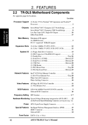
... Features ATI Rage-XL PCI VGA Controller 11 (1) VGA Monitor Port 24 SCSI Features LSI 64-bit 66MHz Ultra160/320 SCSI controller 9 Onboard SCSI Connectors 10 Frequency Setting DIP Switches 3, 7 Hardware Monitoring System Voltage Monitoring (integrated in ASUS ASIC) ....... 12 (4) Fan Power & Speed Monitoring Connectors (see layout ...Features Intelligent Platform Management Interface (IPMI 15 eRMC Connector 16 Onboard LED 14 Form Factor EATX (12 in .) 12 ASUS TR-DLS User's Manual FEATURES MB Components 2. x 10 in . Location Processor Support (2) Socket 370 for locations.
... Features ATI Rage-XL PCI VGA Controller 11 (1) VGA Monitor Port 24 SCSI Features LSI 64-bit 66MHz Ultra160/320 SCSI controller 9 Onboard SCSI Connectors 10 Frequency Setting DIP Switches 3, 7 Hardware Monitoring System Voltage Monitoring (integrated in ASUS ASIC) ....... 12 (4) Fan Power & Speed Monitoring Connectors (see layout ...Features Intelligent Platform Management Interface (IPMI 15 eRMC Connector 16 Onboard LED 14 Form Factor EATX (12 in .) 12 ASUS TR-DLS User's Manual FEATURES MB Components 2. x 10 in . Location Processor Support (2) Socket 370 for locations.
TR-DLS User Manual
Page 14
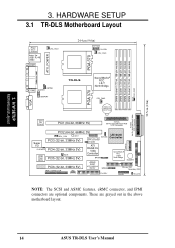
...PGA 370 PARALLEL PORT ATX_POWER KBPWR COM2 CHASSIS USBPORT TR-DLS ServerWorks® RCC LE-T North Bridge CPU_FAN2 PGA 370 VGA CR2032 3V Lithium Cell CMOS Power 01 23 45 67 SCSI-B 68-Pin Ultra160/Ultra2-Wide SCSI Connector Intel Fast Ethernet PCI1 (64-bit, 66MHz ... Monitor BPSMB Primary IDE1 Secondary IDE2 eRMC CONNECTOR IPMI FLOPPY PANEL HD_LED NOTE: The SCSI and ASMC features, eRMC connector, and IPMI connectors are grayed out in the above motherboard layout. 14 ASUS TR-DLS User's Manual These are optional components. H/W SETUP Motherboard Layout 3. 30.5cm (12in...
...PGA 370 PARALLEL PORT ATX_POWER KBPWR COM2 CHASSIS USBPORT TR-DLS ServerWorks® RCC LE-T North Bridge CPU_FAN2 PGA 370 VGA CR2032 3V Lithium Cell CMOS Power 01 23 45 67 SCSI-B 68-Pin Ultra160/Ultra2-Wide SCSI Connector Intel Fast Ethernet PCI1 (64-bit, 66MHz ... Monitor BPSMB Primary IDE1 Secondary IDE2 eRMC CONNECTOR IPMI FLOPPY PANEL HD_LED NOTE: The SCSI and ASMC features, eRMC connector, and IPMI connectors are grayed out in the above motherboard layout. 14 ASUS TR-DLS User's Manual These are optional components. H/W SETUP Motherboard Layout 3. 30.5cm (12in...
TR-DLS User Manual
Page 15
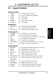
...) 4) WOL_CON p. 33 Wake-On-LAN Connector (3-pin) 5) WOR p. 33 Wake-On-Ring Connector (2-pin) 6) SCSI-A/SCSI-B p. 34 68-pin Ultra160 SCSI Connectors (two 68-pin) 7) CPU_FAN1/2 p. 35 CPU and Chassis Fan Connectors (four 3-pin) CHA_FAN1/2 8) CHASSIS ...p. 33 Chassis Open Alarm Lead (4-1 pin) 9) SMB, BPSMB p. 36 SMBus Connectors (two 6-1 pins) 10 USBPORT p. 36 Universal Serial Port Header (10-1pin male) 11) ATXPWR p. 37 ATX Power Supply Connector (20/24-pin) ASUS TR-DLS...
...) 4) WOL_CON p. 33 Wake-On-LAN Connector (3-pin) 5) WOR p. 33 Wake-On-Ring Connector (2-pin) 6) SCSI-A/SCSI-B p. 34 68-pin Ultra160 SCSI Connectors (two 68-pin) 7) CPU_FAN1/2 p. 35 CPU and Chassis Fan Connectors (four 3-pin) CHA_FAN1/2 8) CHASSIS ...p. 33 Chassis Open Alarm Lead (4-1 pin) 9) SMB, BPSMB p. 36 SMBus Connectors (two 6-1 pins) 10 USBPORT p. 36 Universal Serial Port Header (10-1pin male) 11) ATXPWR p. 37 ATX Power Supply Connector (20/24-pin) ASUS TR-DLS...
TR-DLS User Manual
Page 16
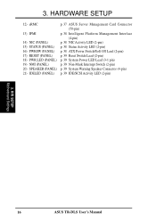
3. HARDWARE SETUP 12) eRMC p. 37 ASUS Server Management Card Connector (50-pin) 13) IPMI p. 38 Intelligent Platform Management Interface (4-pin) 14) NIC (PANEL) p. 38 NIC Activity LED (2-pin) 15) STATUS (PANEL) p. ... Lead (3-1 pin) 19) NMI (PANEL) p. 39 Non-Mask Interrupt Switch (2-pin) 20) SPEAKER (PANEL) p. 39 System Warning Speaker Connector (4-pin) 21) IDELED (PANEL) p. 39 IDE/SCSI Activity LED (2-pin) 3. H/W SETUP Motherboard Settings 16 ASUS TR-DLS User's Manual
3. HARDWARE SETUP 12) eRMC p. 37 ASUS Server Management Card Connector (50-pin) 13) IPMI p. 38 Intelligent Platform Management Interface (4-pin) 14) NIC (PANEL) p. 38 NIC Activity LED (2-pin) 15) STATUS (PANEL) p. ... Lead (3-1 pin) 19) NMI (PANEL) p. 39 Non-Mask Interrupt Switch (2-pin) 20) SPEAKER (PANEL) p. 39 System Warning Speaker Connector (4-pin) 21) IDELED (PANEL) p. 39 IDE/SCSI Activity LED (2-pin) 3. H/W SETUP Motherboard Settings 16 ASUS TR-DLS User's Manual
TR-DLS User Manual
Page 21
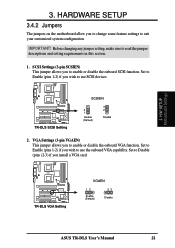
... allows you to read the jumper descriptions and setting requirements in this section. 1. TR-DLS TR-DLS VGA Setting VGAEN 12 Enable (Default) 23 Disable ASUS TR-DLS User's Manual 21 Before changing any jumper setting, make sure to enable or disable the onboard SCSI function. TR-DLS TR-DLS SCSI Setting SCSIEN 2 1 Enable (Default) 3 2 Disable 2. Set to Enable (pins 1-2) if you install.... VGA Settings (3-pin VGAEN) This jumper allows you to change some feature settings to enable or disable the onboard VGA function. IMPORTANT! 3. Set to use SCSI devices.
... allows you to read the jumper descriptions and setting requirements in this section. 1. TR-DLS TR-DLS VGA Setting VGAEN 12 Enable (Default) 23 Disable ASUS TR-DLS User's Manual 21 Before changing any jumper setting, make sure to enable or disable the onboard SCSI function. TR-DLS TR-DLS SCSI Setting SCSIEN 2 1 Enable (Default) 3 2 Disable 2. Set to Enable (pins 1-2) if you install.... VGA Settings (3-pin VGAEN) This jumper allows you to change some feature settings to enable or disable the onboard VGA function. IMPORTANT! 3. Set to use SCSI devices.
TR-DLS User Manual
Page 27
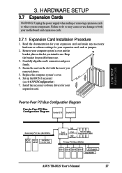
... Bus (66/33MHz) PCI-1 PCI-2 LSI SCSI 64-bit 64-bit 1010R/1030 MA RCC CNB30LE Cntl MD 100/133MHz 100/133 MHz Registered DIMM Primary PCI Bus (33MHz) PCI-3 PCI-4 PCI-5 PCI-6 ATI RageXL 32-bit 32-bit 32-bit 32-bit Intel 82550 ASUS TR-DLS User's Manual 27 Replace the computer...
... Bus (66/33MHz) PCI-1 PCI-2 LSI SCSI 64-bit 64-bit 1010R/1030 MA RCC CNB30LE Cntl MD 100/133MHz 100/133 MHz Registered DIMM Primary PCI Bus (33MHz) PCI-3 PCI-4 PCI-5 PCI-6 ATI RageXL 32-bit 32-bit 32-bit 32-bit Intel 82550 ASUS TR-DLS User's Manual 27 Replace the computer...
TR-DLS User Manual
Page 32
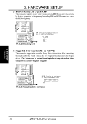
... to the primary/secondary IDE and SCSI connectors cause the LED to the chassis activity LED. TR-DLS TIP: If the case-mounted LED does not light, try reversing the 2-pin plug. H/W SETUP Connectors 32 ASUS TR-DLS User's Manual HD_LED + TR-DLS HD Activity LED 3) Floppy Disk ...Drive Connector (34-1 pin FLOPPY) This connector supports the provided floppy drive ribbon cable. HARDWARE SETUP 2) IDE/SCSI Activity LED (2-pin HDLED) This connector supplies power ...
... to the primary/secondary IDE and SCSI connectors cause the LED to the chassis activity LED. TR-DLS TIP: If the case-mounted LED does not light, try reversing the 2-pin plug. H/W SETUP Connectors 32 ASUS TR-DLS User's Manual HD_LED + TR-DLS HD Activity LED 3) Floppy Disk ...Drive Connector (34-1 pin FLOPPY) This connector supports the provided floppy drive ribbon cable. HARDWARE SETUP 2) IDE/SCSI Activity LED (2-pin HDLED) This connector supplies power ...
TR-DLS User Manual
Page 34
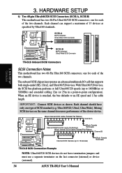
... that supports both single-ended (SE), Ultra2, and Ultra160/320 devices. When an SE device is attached, the bus defaults to -point configuration). Mixing SCSI devices on the last connector (internal) or device (external). 34 ASUS TR-DLS User's Manual Each channel can support a maximum of the two channels. With Ultra160/320 devices, the...
... that supports both single-ended (SE), Ultra2, and Ultra160/320 devices. When an SE device is attached, the bus defaults to -point configuration). Mixing SCSI devices on the last connector (internal) or device (external). 34 ASUS TR-DLS User's Manual Each channel can support a maximum of the two channels. With Ultra160/320 devices, the...
TR-DLS User Manual
Page 39
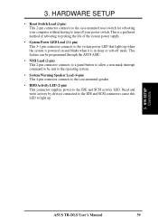
Read and write activity by devices connected to the IDE and SCSI connectors cause this LED to the system power LED that lights up . 3. H/W SETUP Connectors ASUS TR-DLS User's Manual 39 This feature can be programmed through the ASUS ASIC. • NMI Lead (2-pin) This 2-pin connector connects to a panel button to allow a non-mask... • Reset Switch Lead (2-pin) This 2-pin connector connects to the case-mounted reset switch for rebooting your computer without having to the IDE and SCSI activity LED. 3.
Read and write activity by devices connected to the IDE and SCSI connectors cause this LED to the system power LED that lights up . 3. H/W SETUP Connectors ASUS TR-DLS User's Manual 39 This feature can be programmed through the ASUS ASIC. • NMI Lead (2-pin) This 2-pin connector connects to a panel button to allow a non-mask... • Reset Switch Lead (2-pin) This 2-pin connector connects to the case-mounted reset switch for rebooting your computer without having to the IDE and SCSI activity LED. 3.
TR-DLS User Manual
Page 40
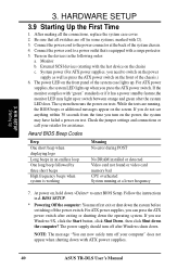
... power cord to switch on the power supply as well as press the ATX power switch on the chain) c. Turn on the devices in 4. External SCSI devices (starting with a surge protector. 5. For ATX power supplies, the system LED lights up when you use Windows 9X, click the Start button, click ... with "green" standards or if it has a power standby feature,the monitor LED may have failed a power-on , hold down with ATX power supplies. 40 ASUS TR-DLS User's Manual At power on test. BIOS SETUP. * Powering Off the computer: You must first exit or shut down the system before switching off after...
... power cord to switch on the power supply as well as press the ATX power switch on the chain) c. Turn on the devices in 4. External SCSI devices (starting with a surge protector. 5. For ATX power supplies, the system LED lights up when you use Windows 9X, click the Start button, click ... with "green" standards or if it has a power standby feature,the monitor LED may have failed a power-on , hold down with ATX power supplies. 40 ASUS TR-DLS User's Manual At power on test. BIOS SETUP. * Powering Off the computer: You must first exit or shut down the system before switching off after...
TR-DLS User Manual
Page 59
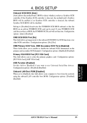
... allows you want to enable or disable the onboard SCSI termination on SYMBIOS SCSI card can be used. BIOS SETUP PCI Configuration ASUS TR-DLS User's Manual 59 4. If the Symbios SCSI controller is detected, the onboard Symbios SCSI BIOS will not function. Configuration options: [Auto] [Disabled] ONB SCSI BIOS First [No] This field allows giving priority to...
... allows you want to enable or disable the onboard SCSI termination on SYMBIOS SCSI card can be used. BIOS SETUP PCI Configuration ASUS TR-DLS User's Manual 59 4. If the Symbios SCSI controller is detected, the onboard Symbios SCSI BIOS will not function. Configuration options: [Auto] [Disabled] ONB SCSI BIOS First [No] This field allows giving priority to...

TR-DLS User Manual
Page 61
... video display card if it supports the DPMS feature. [Blank Screen] only blanks the screen (use this user-configurable field. BIOS SETUP Power Menu ASUS TR-DLS User's Manual 61 Configuration options: [Soft off features. Configuration options: [Disabled] [1~2 Min] [2~3 Min]...[1 Hour] PWR Button < 4 Secs ...BIOS SETUP Video Off Option [Suspend -> Off ] This field determines when to activate the video off the system. This feature does not affect SCSI hard drives. Configuration options: [Disabled] [1 Min] [2 Min] [3 Min]...[15 Min] Suspend Mode [Disabled] This sets the time period ...
... video display card if it supports the DPMS feature. [Blank Screen] only blanks the screen (use this user-configurable field. BIOS SETUP Power Menu ASUS TR-DLS User's Manual 61 Configuration options: [Soft off features. Configuration options: [Disabled] [1~2 Min] [2~3 Min]...[1 Hour] PWR Button < 4 Secs ...BIOS SETUP Video Off Option [Suspend -> Off ] This field determines when to activate the video off the system. This feature does not affect SCSI hard drives. Configuration options: [Disabled] [1 Min] [2 Min] [3 Min]...[15 Min] Suspend Mode [Disabled] This sets the time period ...
TR-DLS User Manual
Page 65
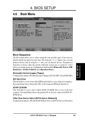
...] IDE Hard Drive This field allows you to use in the boot sequence. Other Boot Device Select [INT18 Device (Network)] Configuration options: [Disabled] [SCSI Boot Device] [INT18 Device (Network)] ASUS TR-DLS User's Manual 65 BIOS SETUP 4.6 Boot Menu 4. Configuration fields include Removable Devices, IDE Hard Drive, ATAPI CD-ROM, and Other Boot Device...
...] IDE Hard Drive This field allows you to use in the boot sequence. Other Boot Device Select [INT18 Device (Network)] Configuration options: [Disabled] [SCSI Boot Device] [INT18 Device (Network)] ASUS TR-DLS User's Manual 65 BIOS SETUP 4.6 Boot Menu 4. Configuration fields include Removable Devices, IDE Hard Drive, ATAPI CD-ROM, and Other Boot Device...
TR-DLS User Manual
Page 72
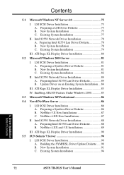
...Driver Installation Table of Contents 72 ASUS TR-DLS User's Manual New System Installation 78 C. Existing System Installation 79 III. Preparing Intel 82550 Lan Driver Diskette 84 B. Preparing Intel 82550 Lan Driver Diskette 88 B. LSI SCSI Driver Installation 75 A. LSI SCSI Driver Installation 81 A. Intel ... 75 C. Existing System Installation 77 II. NetWare 5.X New Installations 87 C. NetWare 4.XX New Installations 87 II. LSI SCSI Driver Installation 86 A. ATI Rage XL Display Driver Installation 90 5.5 SUN Solaris 7 Server 90 I . ATI Rage XL Display Driver Installation...
...Driver Installation Table of Contents 72 ASUS TR-DLS User's Manual New System Installation 78 C. Existing System Installation 79 III. Preparing Intel 82550 Lan Driver Diskette 84 B. Preparing Intel 82550 Lan Driver Diskette 88 B. LSI SCSI Driver Installation 75 A. LSI SCSI Driver Installation 81 A. Intel ... 75 C. Existing System Installation 77 II. NetWare 5.X New Installations 87 C. NetWare 4.XX New Installations 87 II. LSI SCSI Driver Installation 86 A. ATI Rage XL Display Driver Installation 90 5.5 SUN Solaris 7 Server 90 I . ATI Rage XL Display Driver Installation...

TR-DLS User Manual
Page 73
LSI SCSI Driver Installation 96 A. Existing System Installation 98 II. Driver Installation Table of Contents ASUS TR-DLS User's Manual 73 Building the SCO OpenServer BTLD Diskette ....... 96 B. ATI Rage XL Display ...Driver Installation 100 5.7 SCO UnixWare Server 100 I . New System Installation 101 C. ATI Rage XL Display Driver Installation 95 5.6 SCO Open Server 5.0.x 96 I . ATI Rage XL Display Driver Installation 103 5.8 Linux RedHat 7.x 104 I. LSI SCSI...
LSI SCSI Driver Installation 96 A. Existing System Installation 98 II. Driver Installation Table of Contents ASUS TR-DLS User's Manual 73 Building the SCO OpenServer BTLD Diskette ....... 96 B. ATI Rage XL Display ...Driver Installation 100 5.7 SCO UnixWare Server 100 I . New System Installation 101 C. ATI Rage XL Display Driver Installation 95 5.6 SCO Open Server 5.0.x 96 I . ATI Rage XL Display Driver Installation 103 5.8 Linux RedHat 7.x 104 I. LSI SCSI...
TR-DLS User Manual
Page 75
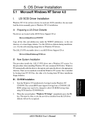
... the Windows NT system. CD-ROM Installation 1. When the screen displays "Windows NT Setup", immediately press the F6 key. Driver Installation WinNT4.0 Server ASUS TR-DLS User's Manual 75 Preparing a LSI Driver Diskette The drivers are two methods to the root directory of a clean floppy diskette. The LSI_U3.SYS executable...booting from a CD-ROM. Windows NT automatically adds the driver to the registry and copies the driver to allow CD-ROM booting when using SCSI-interface CD-ROM drive. 2. The system BIOS must be done or else the new driver installed from the Windows NT CD-ROM. LSI ...
... the Windows NT system. CD-ROM Installation 1. When the screen displays "Windows NT Setup", immediately press the F6 key. Driver Installation WinNT4.0 Server ASUS TR-DLS User's Manual 75 Preparing a LSI Driver Diskette The drivers are two methods to the root directory of a clean floppy diskette. The LSI_U3.SYS executable...booting from a CD-ROM. Windows NT automatically adds the driver to the registry and copies the driver to allow CD-ROM booting when using SCSI-interface CD-ROM drive. 2. The system BIOS must be done or else the new driver installed from the Windows NT CD-ROM. LSI ...