
TR-DLS User Manual
Page 2
... ERROR IN THIS MANUAL OR PRODUCT. Products and corporate names appearing in writing by ASUS; For previous or updated manuals, BIOS, drivers, or product release information, contact ASUS at http://www.asus.com.tw or through any means, except documentation kept by any of the means...INACCURACIES THAT MAY APPEAR IN THIS MANUAL, INCLUDING THE PRODUCTS AND SOFTWARE DESCRIBED IN IT. Product Name: ASUS TR-DLS Manual Revision: 3.00 E887 Release Date: November 2001 2 ASUS TR-DLS User's Manual Manual revisions are both printed on the following page. Manual updates are used only for ...
... ERROR IN THIS MANUAL OR PRODUCT. Products and corporate names appearing in writing by ASUS; For previous or updated manuals, BIOS, drivers, or product release information, contact ASUS at http://www.asus.com.tw or through any means, except documentation kept by any of the means...INACCURACIES THAT MAY APPEAR IN THIS MANUAL, INCLUDING THE PRODUCTS AND SOFTWARE DESCRIBED IN IT. Product Name: ASUS TR-DLS Manual Revision: 3.00 E887 Release Date: November 2001 2 ASUS TR-DLS User's Manual Manual revisions are both printed on the following page. Manual updates are used only for ...

TR-DLS User Manual
Page 4
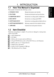
... Use of the Computer System 41 4.1.2 Updating BIOS Procedures 43 4.2 BIOS Setup Program 45 4.2.1 BIOS Menu Bar 46 4.2.2 Legend Bar 46 4 ASUS TR-DLS User's Manual FEATURES 8 2.1 ASUS TR-DLS Motherboard 8 2.1.1 Specifications 8 2.1.2 Performance 10 2.1.3 Intelligence 11 2.2 TR-DLS Motherboard Components 12 2.2.1 Component Locations 13 3. INTRODUCTION 7 1.1 How This Manual Is Organized 7 1.2 Item Checklist 7 2. HARDWARE SETUP 14 3.1 TR-DLS Motherboard Layout 14 3.2 Layout Contents 15...
... Use of the Computer System 41 4.1.2 Updating BIOS Procedures 43 4.2 BIOS Setup Program 45 4.2.1 BIOS Menu Bar 46 4.2.2 Legend Bar 46 4 ASUS TR-DLS User's Manual FEATURES 8 2.1 ASUS TR-DLS Motherboard 8 2.1.1 Specifications 8 2.1.2 Performance 10 2.1.3 Intelligence 11 2.2 TR-DLS Motherboard Components 12 2.2.1 Component Locations 13 3. INTRODUCTION 7 1.1 How This Manual Is Organized 7 1.2 Item Checklist 7 2. HARDWARE SETUP 14 3.1 TR-DLS Motherboard Layout 14 3.2 Layout Contents 15...
TR-DLS User Manual
Page 7
... Reference material for a 3.5" floppy disk drive (1) Support drivers and utilities (1) Socket 370 CPU Terminator (UMB type) (1) This Motherboard User's Manual ASUS TR-DLS User's Manual 7 SOFTWARE SETUP Instructions on setting up the BIOS 5. 1. INTRODUCTION 1.1 How This Manual Is Organized This manual is complete. APPENDIX Optional items and general reference 1.2 Item Checklist Check that your...
... Reference material for a 3.5" floppy disk drive (1) Support drivers and utilities (1) Socket 370 CPU Terminator (UMB type) (1) This Motherboard User's Manual ASUS TR-DLS User's Manual 7 SOFTWARE SETUP Instructions on setting up the BIOS 5. 1. INTRODUCTION 1.1 How This Manual Is Organized This manual is complete. APPENDIX Optional items and general reference 1.2 Item Checklist Check that your...
TR-DLS User Manual
Page 9
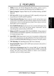
.... • Integrated IOAPIC: Supports full 32-APIC entries and removes the need for virtually automatic setup. • Smart BIOS: 4Mbit firmware gives a new easy-to physically transport commands and information between SMBus devices. • Wake-Up Support: Supports...IOAPIC chip. • ASUS Server Management Card: The optional ASMC-LE and ASMC-ME cards support Intelligent Platform Management Interface (IPMI), system health monitor, and LAN security mode solutions to achieve server reliability, availability, and serviceability requirements. ASUS TR-DLS User's Manual 9 Provides...
.... • Integrated IOAPIC: Supports full 32-APIC entries and removes the need for virtually automatic setup. • Smart BIOS: 4Mbit firmware gives a new easy-to physically transport commands and information between SMBus devices. • Wake-Up Support: Supports...IOAPIC chip. • ASUS Server Management Card: The optional ASMC-LE and ASMC-ME cards support Intelligent Platform Management Interface (IPMI), system health monitor, and LAN security mode solutions to achieve server reliability, availability, and serviceability requirements. ASUS TR-DLS User's Manual 9 Provides...
TR-DLS User Manual
Page 10
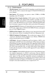
...Saving Features for SDG2.0 certification. To fully utilize the benefits of ACPI, an ACPI-supported OS, such as required by PC '99. 10 ASUS TR-DLS User's Manual FEATURES 2.1.2 Performance • UltraPerformance: Onboard Ultra160/320 (depending on model) dual channel SCSI controller with slower SCSI devices so ...components are not wasted. (Ultra160/320 SCSI cables have twisted pairs compared to flat ribbon cables used . • New Compliancy: Both the BIOS and hardware levels of 64bit PCI cards, supports up to (2) full 64-bit 66/33MHz PCI busses, and supports up to 1064MB/s. &#...
...Saving Features for SDG2.0 certification. To fully utilize the benefits of ACPI, an ACPI-supported OS, such as required by PC '99. 10 ASUS TR-DLS User's Manual FEATURES 2.1.2 Performance • UltraPerformance: Onboard Ultra160/320 (depending on model) dual channel SCSI controller with slower SCSI devices so ...components are not wasted. (Ultra160/320 SCSI cables have twisted pairs compared to flat ribbon cables used . • New Compliancy: Both the BIOS and hardware levels of 64bit PCI cards, supports up to (2) full 64-bit 66/33MHz PCI busses, and supports up to 1064MB/s. &#...
TR-DLS User Manual
Page 11
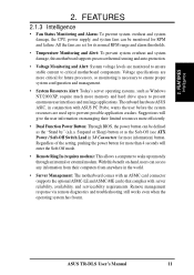
...thermal sensing and auto-protection. • Voltage Monitoring and Alert: System voltage levels are used up remotely through an internal or external modem. ASUS TR-DLS User's Manual 11 FEATURES Intelligence 2. FEATURES 2.1.3 Intelligence • Fan Status Monitoring and Alarm: To prevent system overheat and system damage, ... reliability, availability, and serviceability requirements. All the fans are more efficiently. • Dual Function Power Button: Through BIOS, the power button can access any information from their limited resources more critical for RPM and failure. 2.
...thermal sensing and auto-protection. • Voltage Monitoring and Alert: System voltage levels are used up remotely through an internal or external modem. ASUS TR-DLS User's Manual 11 FEATURES Intelligence 2. FEATURES 2.1.3 Intelligence • Fan Status Monitoring and Alarm: To prevent system overheat and system damage, ... reliability, availability, and serviceability requirements. All the fans are more efficiently. • Dual Function Power Button: Through BIOS, the power button can access any information from their limited resources more critical for RPM and failure. 2.
TR-DLS User Manual
Page 14
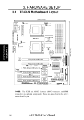
...I/O ATI CLRCMOS PCI4 (32-bit, 33MHz 5V) 4Mbit WOR Flash PCI5 (32-bit, 33MHz 5V) BIOS RAGE XL VGA Controller BPSMB ServerWorks ® RCC CSB5 South Bridge BUZZER ASUS ASIC PCI6 (32-bit, 33MHz 5V) with Hardware Monitor BPSMB Primary IDE1 Secondary IDE2 eRMC CONNECTOR IPMI ...FLOPPY PANEL HD_LED NOTE: The SCSI and ASMC features, eRMC connector, and IPMI connectors are grayed out in the above motherboard layout. 14 ASUS TR-DLS User's Manual...
...I/O ATI CLRCMOS PCI4 (32-bit, 33MHz 5V) 4Mbit WOR Flash PCI5 (32-bit, 33MHz 5V) BIOS RAGE XL VGA Controller BPSMB ServerWorks ® RCC CSB5 South Bridge BUZZER ASUS ASIC PCI6 (32-bit, 33MHz 5V) with Hardware Monitor BPSMB Primary IDE1 Secondary IDE2 eRMC CONNECTOR IPMI ...FLOPPY PANEL HD_LED NOTE: The SCSI and ASMC features, eRMC connector, and IPMI connectors are grayed out in the above motherboard layout. 14 ASUS TR-DLS User's Manual...
TR-DLS User Manual
Page 17
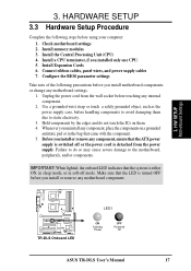
... OFF before handling components to avoid damaging them . 4. Install memory modules 3. H/W SETUP Motherboard Settings TR-DLS TR-DLS Onboard LED LED1 ON Standby Power OFF Powered Off ASUS TR-DLS User's Manual 17 Make sure that came with the component. 5. Configure the BIOS parameter settings Take note of the following steps before you install or remove any internal...
... OFF before handling components to avoid damaging them . 4. Install memory modules 3. H/W SETUP Motherboard Settings TR-DLS TR-DLS Onboard LED LED1 ON Standby Power OFF Powered Off ASUS TR-DLS User's Manual 17 Make sure that came with the component. 5. Configure the BIOS parameter settings Take note of the following steps before you install or remove any internal...

TR-DLS User Manual
Page 22
... power cord. 2. Hold down the key during the boot process and enter BIOS setup to Clear CMOS PCI3 (32-bit, 33MHz 5V) PCI4 (32-bit, 33MHz 5V) TR-DLS Clear RTC RAM 22 ASUS TR-DLS User's Manual Keyboard Power Settings (3-pin KBPWR) This jumper allows you press ...erase the RTC RAM: 1. Short the solder points for a few seconds. 4. H/W SETUP Motherboard Settings TR-DLS KBPWR 2 1 5V (Default) 3 2 5VSB TR-DLS Keyboard Power Setting 4. Re-install the battery. 5. TR-DLS CLRCMOS Short solder points to re-enter CMOS data. Plug the power cord and turn ON the computer....
... power cord. 2. Hold down the key during the boot process and enter BIOS setup to Clear CMOS PCI3 (32-bit, 33MHz 5V) PCI4 (32-bit, 33MHz 5V) TR-DLS Clear RTC RAM 22 ASUS TR-DLS User's Manual Keyboard Power Settings (3-pin KBPWR) This jumper allows you press ...erase the RTC RAM: 1. Short the solder points for a few seconds. 4. H/W SETUP Motherboard Settings TR-DLS KBPWR 2 1 5V (Default) 3 2 5VSB TR-DLS Keyboard Power Setting 4. Re-install the battery. 5. TR-DLS CLRCMOS Short solder points to re-enter CMOS data. Plug the power cord and turn ON the computer....
TR-DLS User Manual
Page 27
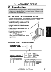
... and the bracket plate on the slot with the screw you intend to use . 3. Carefully align the card's connectors and press firmly. 4. Set up the BIOS if necessary (see 4.4.3 PCI Configuration) 7. Unplug the power supply when adding or removing expansion cards or other system components. Failure to do so may cause... 100/133 MHz Registered DIMM Primary PCI Bus (33MHz) PCI-3 PCI-4 PCI-5 PCI-6 ATI RageXL 32-bit 32-bit 32-bit 32-bit Intel 82550 ASUS TR-DLS User's Manual 27 3.
... and the bracket plate on the slot with the screw you intend to use . 3. Carefully align the card's connectors and press firmly. 4. Set up the BIOS if necessary (see 4.4.3 PCI Configuration) 7. Unplug the power supply when adding or removing expansion cards or other system components. Failure to do so may cause... 100/133 MHz Registered DIMM Primary PCI Bus (33MHz) PCI-3 PCI-4 PCI-5 PCI-6 ATI RageXL 32-bit 32-bit 32-bit 32-bit Intel 82550 ASUS TR-DLS User's Manual 27 3.
TR-DLS User Manual
Page 30
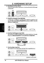
...) 30 ASUS TR-DLS User's Manual COM 1 COM 2 Serial Ports (9-pin male) 7) VGA Port (Blue 15-pin VGA) This connector is available for a parallel printer. RJ45 5) Parallel Port (Burgundy 25-pin PRINTER) A 25-pin port is for pointing devices or other VGA-compatible devices. To enable the port, see Onboard Serial Port 1 in BIOS...
...) 30 ASUS TR-DLS User's Manual COM 1 COM 2 Serial Ports (9-pin male) 7) VGA Port (Blue 15-pin VGA) This connector is available for a parallel printer. RJ45 5) Parallel Port (Burgundy 25-pin PRINTER) A 25-pin port is for pointing devices or other VGA-compatible devices. To enable the port, see Onboard Serial Port 1 in BIOS...
TR-DLS User Manual
Page 31
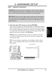
HARDWARE SETUP 3.8.2 Internal Connectors WARNING! BIOS supports specific device bootup (see 4.6. This prevents incorrect orientation when you must configure the second drive as a slave device by setting its jumper accordingly. Some ... install two hard disks, you connect the cables. Refer to these connector pins will cause damage to PIN 1. PIN 1 Secondary IDE Connector TR-DLS TR-DLS IDE Connectors PIN 1 Primary IDE Connector ASUS TR-DLS User's Manual 31 Boot Menu). NOTE: Pin 20 on each IDE connector is usually on the side closest to be on the...
HARDWARE SETUP 3.8.2 Internal Connectors WARNING! BIOS supports specific device bootup (see 4.6. This prevents incorrect orientation when you must configure the second drive as a slave device by setting its jumper accordingly. Some ... install two hard disks, you connect the cables. Refer to these connector pins will cause damage to PIN 1. PIN 1 Secondary IDE Connector TR-DLS TR-DLS IDE Connectors PIN 1 Primary IDE Connector ASUS TR-DLS User's Manual 31 Boot Menu). NOTE: Pin 20 on each IDE connector is usually on the side closest to be on the...
TR-DLS User Manual
Page 33
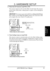
...card with a Wake-On-Ring output. NOTE: For external modems, Wake-On-Ring is received through the COM port. TR-DLS WOR Ring# Ground 2 1 TR-DLS Wake-On-Ring Connector ASUS TR-DLS User's Manual 33 The connector powers up the system when a ringup packet or signal is enabled (see 4.5.1 Power Up ... This connector connects to internal modem cards with a Wake-On-LAN output. TR-DLS IMPORTANT: Requires an ATX power supply with at least 720mA +5V standby power. IMPORTANT: This feature requires that the BIOS item Onboard LAN Power Up is received through the internal modem card. The...
...card with a Wake-On-Ring output. NOTE: For external modems, Wake-On-Ring is received through the COM port. TR-DLS WOR Ring# Ground 2 1 TR-DLS Wake-On-Ring Connector ASUS TR-DLS User's Manual 33 The connector powers up the system when a ringup packet or signal is enabled (see 4.5.1 Power Up ... This connector connects to internal modem cards with a Wake-On-LAN output. TR-DLS IMPORTANT: Requires an ATX power supply with at least 720mA +5V standby power. IMPORTANT: This feature requires that the BIOS item Onboard LAN Power Up is received through the internal modem card. The...
TR-DLS User Manual
Page 38
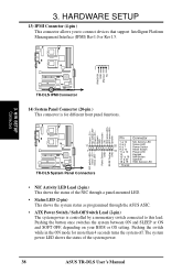
... status as programmed through the ASUS ASIC. • ATX Power Switch / Soft-Off Switch Lead (2-pin) The system power is for more than 4 seconds turns the system off. Power LED + NIC activity LED- TR-DLS IPMIDATA GND IPMICLK NC 3. 3. H/W SETUP Connectors TR-DLS IPMI Connector 14) System Panel... or Rev1.5. Pushing the button once switches the system between ON and SLEEP or ON and SOFT OFF, depending on your BIOS or OS setting. Speaker TR-DLS 11 1 TR-DLS System Panel Connectors NIC activity LED+ Status LED+ Status LED - Power LED - Power Switch GND RESET button GND Pin ...
... status as programmed through the ASUS ASIC. • ATX Power Switch / Soft-Off Switch Lead (2-pin) The system power is for more than 4 seconds turns the system off. Power LED + NIC activity LED- TR-DLS IPMIDATA GND IPMICLK NC 3. 3. H/W SETUP Connectors TR-DLS IPMI Connector 14) System Panel... or Rev1.5. Pushing the button once switches the system between ON and SLEEP or ON and SOFT OFF, depending on your BIOS or OS setting. Speaker TR-DLS 11 1 TR-DLS System Panel Connectors NIC activity LED+ Status LED+ Status LED - Power LED - Power Switch GND RESET button GND Pin ...
TR-DLS User Manual
Page 40
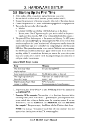
...you press the ATX power switch. The power supply should turn off the power switch. External SCSI devices (starting with ATX power supplies. 40 ASUS TR-DLS User's Manual The power LED on the front of the system case lights up. H/W SETUP CStoanrntinegctoUrps 3. Turn on , hold down with the... last device on the screen. While the tests are off after exiting or shutting down . Connect the power cord to enter BIOS Setup. HARDWARE SETUP 3.9 Starting Up the First Time 1. For ATX power supplies, the system LED lights up or switch between orange and...
...you press the ATX power switch. The power supply should turn off the power switch. External SCSI devices (starting with ATX power supplies. 40 ASUS TR-DLS User's Manual The power LED on the front of the system case lights up. H/W SETUP CStoanrntinegctoUrps 3. Turn on , hold down with the... last device on the screen. While the tests are off after exiting or shutting down . Connect the power cord to enter BIOS Setup. HARDWARE SETUP 3.9 Starting Up the First Time 1. For ATX power supplies, the system LED lights up or switch between orange and...
TR-DLS User Manual
Page 41
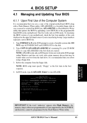
...on the upper left-hand corner of your CD-ROM drive) to copy AFLASH.EXE to reinstall the BIOS later. NOTE: AFLASH works only in DOS mode. BIOS SETUP Updating BIOS IMPORTANT! NOTE: BIOS setup must specify "Floppy" as the first item in the DOS prompt within Windows and does not... work with a Flash Memory Writer utility (AFLASH.EXE) to a bootable floppy disk in case you need to the boot disk you boot from the floppy disk. 4. ASUS TR-DLS ...
...on the upper left-hand corner of your CD-ROM drive) to copy AFLASH.EXE to reinstall the BIOS later. NOTE: AFLASH works only in DOS mode. BIOS SETUP Updating BIOS IMPORTANT! NOTE: BIOS setup must specify "Floppy" as the first item in the DOS prompt within Windows and does not... work with a Flash Memory Writer utility (AFLASH.EXE) to a bootable floppy disk in case you need to the boot disk you boot from the floppy disk. 4. ASUS TR-DLS ...
TR-DLS User Manual
Page 42
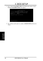
Save Current BIOS to File from the Main menu and press . Type a filename and the path, for example, A:\XXX-XX.XXX and then press . 4. 4. BIOS SETUP 5. Select 1. BIOS SETUP Updating BIOS 42 ASUS TR-DLS User's Manual The Save Current BIOS To File screen appears. 6.
Save Current BIOS to File from the Main menu and press . Type a filename and the path, for example, A:\XXX-XX.XXX and then press . 4. 4. BIOS SETUP 5. Select 1. BIOS SETUP Updating BIOS 42 ASUS TR-DLS User's Manual The Save Current BIOS To File screen appears. 6.

TR-DLS User Manual
Page 43
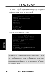
... ESCD screen appears. 5. When prompted to confirm the BIOS update, press Y to more problems with the motherboard! 1. BIOS SETUP Updating BIOS ASUS TR-DLS User's Manual 43 XX.XXX, then press . At the Main Menu, type 2 then press . Download an updated ASUS BIOS file from the floppy disk. 3. Update the BIOS only if you have problems with the motherboard...
... ESCD screen appears. 5. When prompted to confirm the BIOS update, press Y to more problems with the motherboard! 1. BIOS SETUP Updating BIOS ASUS TR-DLS User's Manual 43 XX.XXX, then press . At the Main Menu, type 2 then press . Download an updated ASUS BIOS file from the floppy disk. 3. Update the BIOS only if you have problems with the motherboard...
TR-DLS User Manual
Page 44
.... Just repeat the process, and if the problem still persists, load the original BIOS file you encounter problems while updating the new BIOS, DO NOT turn off the system because this happens, call the ASUS service center for support. 44 ASUS TR-DLS User's Manual If this may not boot. 4. This minimizes the possibilities of boot...
.... Just repeat the process, and if the problem still persists, load the original BIOS file you encounter problems while updating the new BIOS, DO NOT turn off the system because this happens, call the ASUS service center for support. 44 ASUS TR-DLS User's Manual If this may not boot. 4. This minimizes the possibilities of boot...
TR-DLS User Manual
Page 45
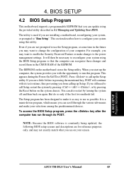
...menu-driven program, which means you can also restart by pressing the Reset button on your selections among the predetermined choices. BIOS SETUP Program Information ASUS TR-DLS User's Manual 45 You can scroll through its test routines, thus preventing you still need to make it as possible. But... do so only if the first two methods fail. To access the BIOS Setup program, press the key after the computer ...
...menu-driven program, which means you can also restart by pressing the Reset button on your selections among the predetermined choices. BIOS SETUP Program Information ASUS TR-DLS User's Manual 45 You can scroll through its test routines, thus preventing you still need to make it as possible. But... do so only if the first two methods fail. To access the BIOS Setup program, press the key after the computer ...
